- Group Assignment:
- Design a machine that includes mechanism + actuation + automation
- Build the mechanical parts and operate it manually.
- Make and compare test casts with each of them
- Make and compare test casts with each of them
- Document the group project
- Individual Assignment:
- Document your individual contribution.
- Work and communicate effectively in a team and independently
- Design, plan and build a system
- Analyse and solve technical problems
- Recognise opportunities for improvements in the design
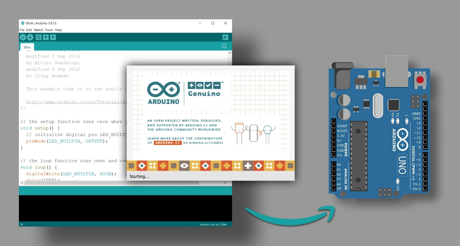
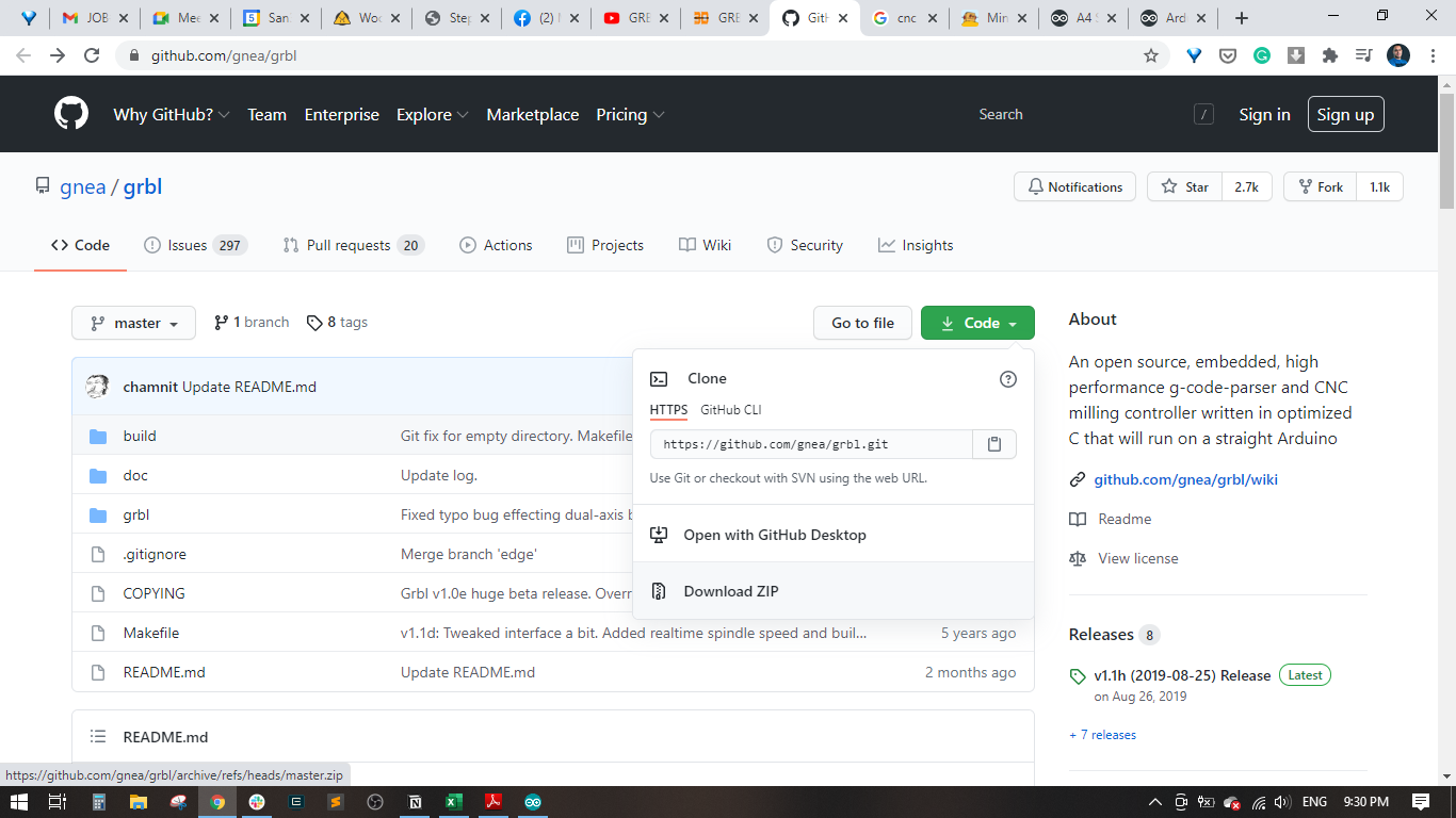
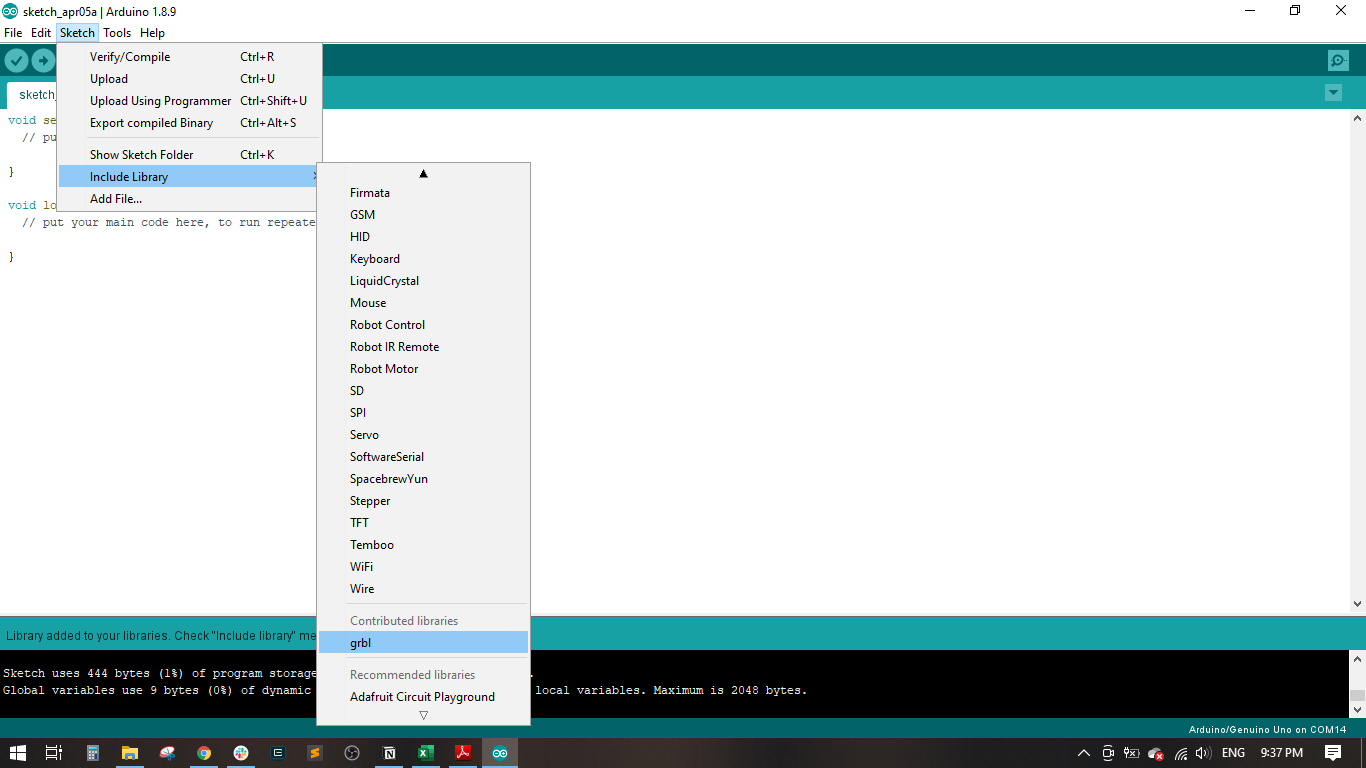
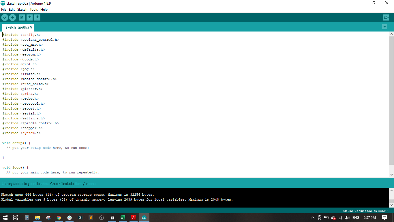
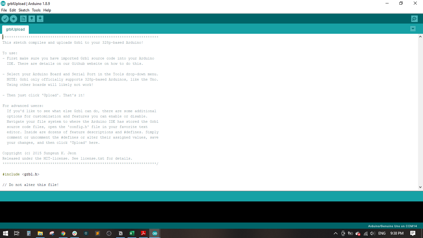
- Loading GRBL
- Coneecting GRBL
- Using GRBL
- CNC Shield First Run
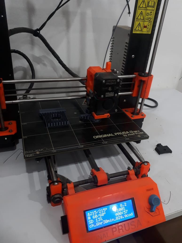
Roland:MDX-20 FabModules KiCad Photoshop Arduino
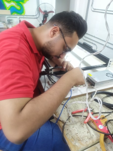
My Work (Assembly)
In this Machine I will Document All the things that I participate in the machine (Assembly) So Keep Tracking
Note I will Leave All Other Works In the Link Below
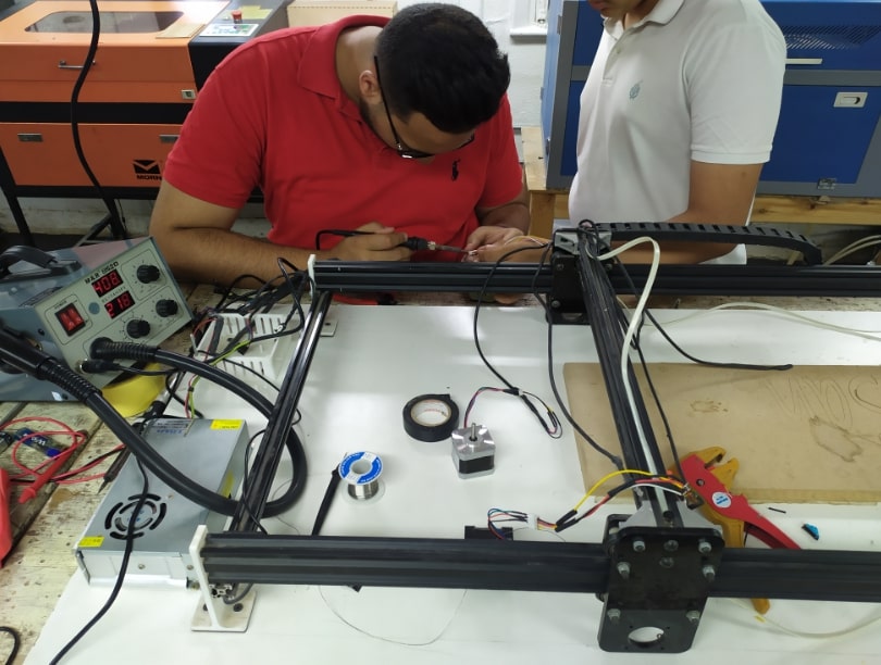
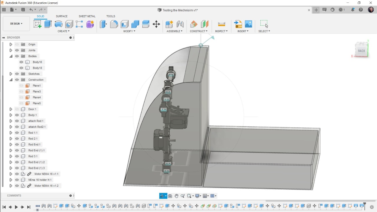
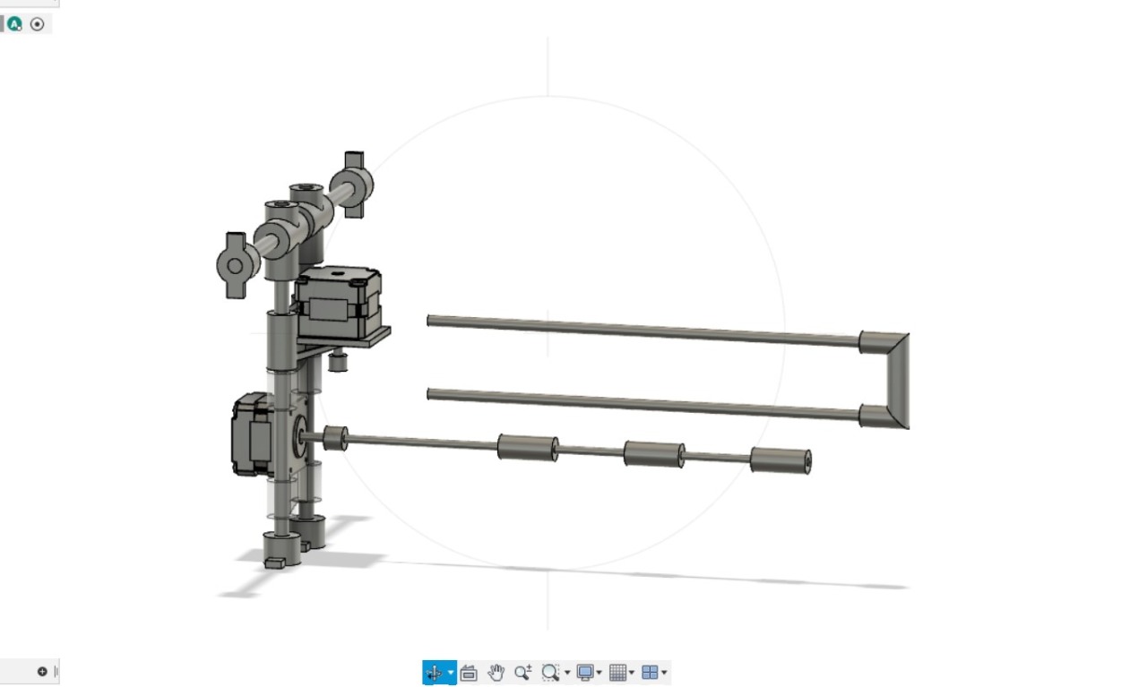
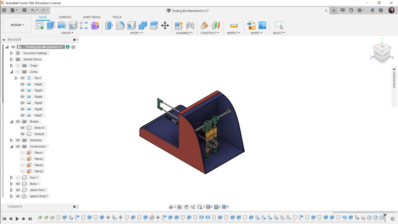
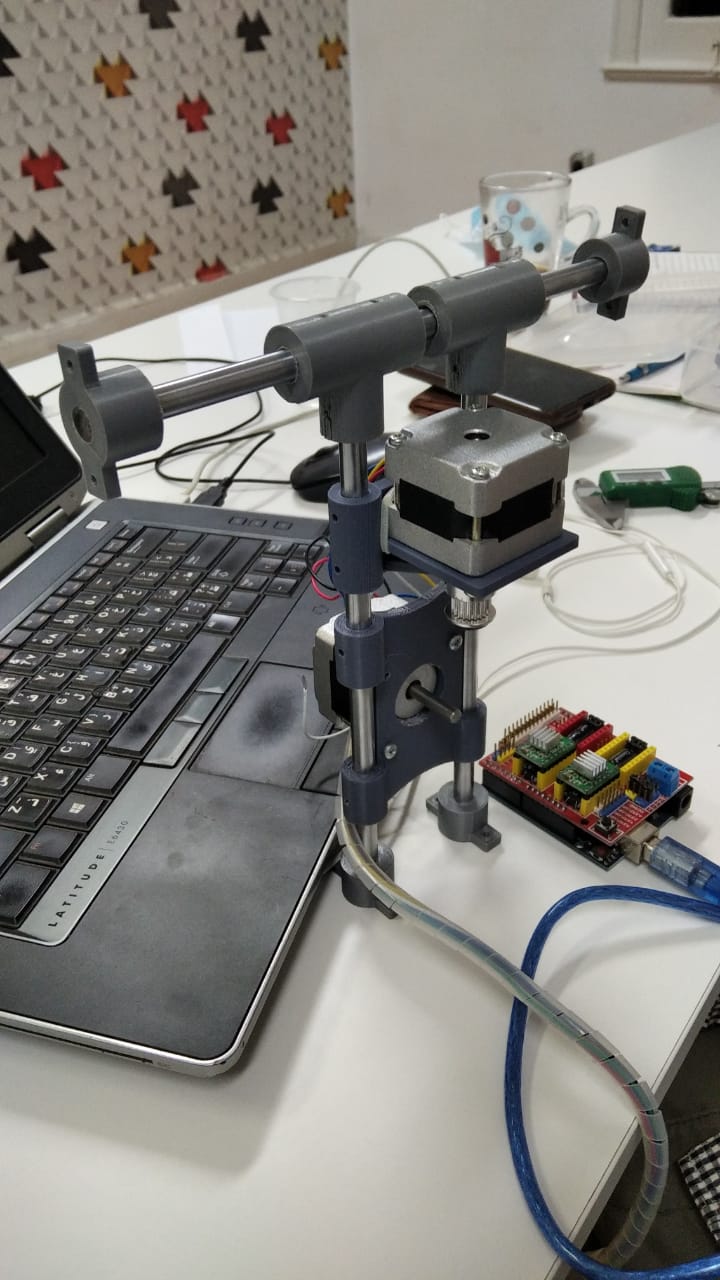
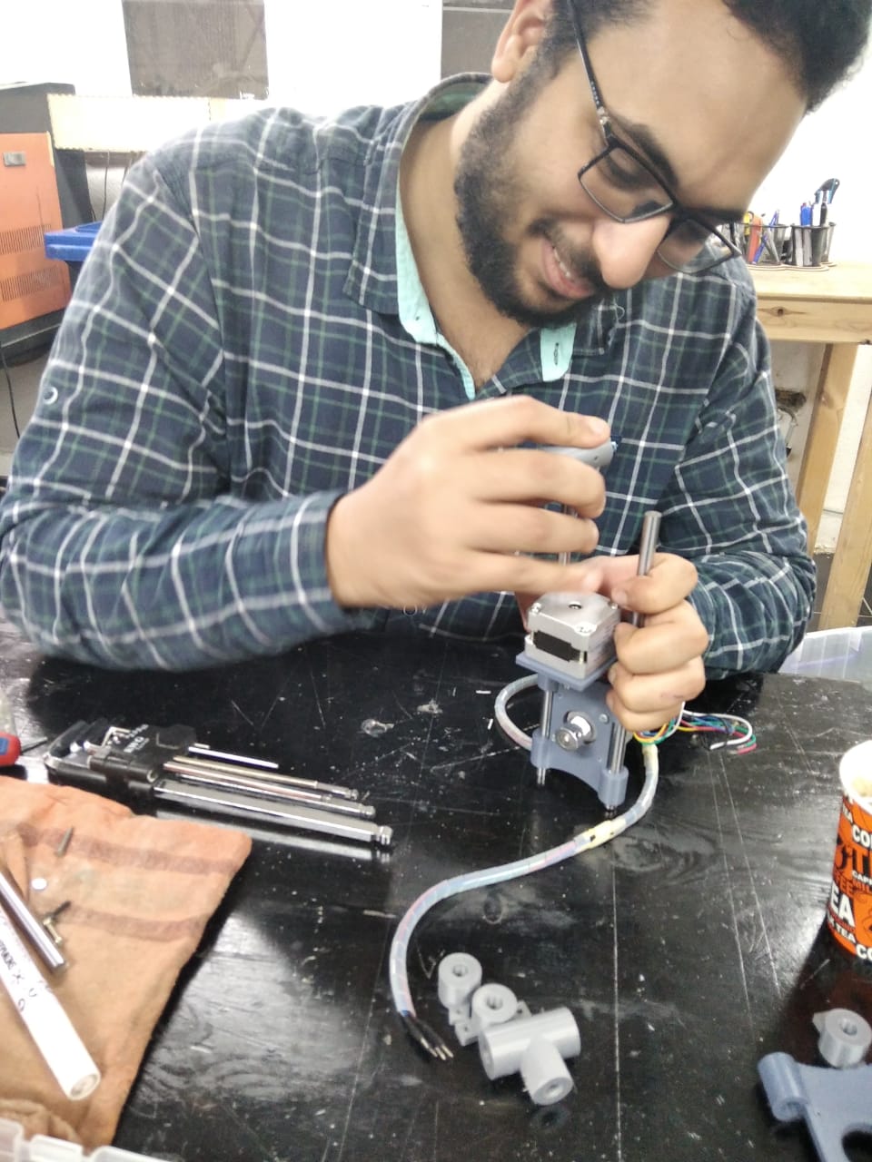
In short All I did I To hold the 3D Corners in the side of the frame as you see

Then Start to Put the Steppers in it's Place
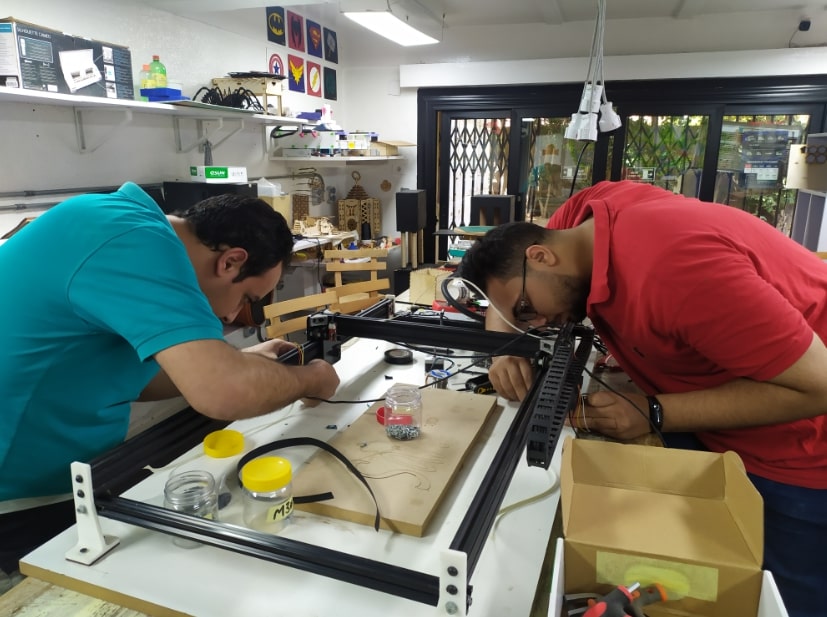
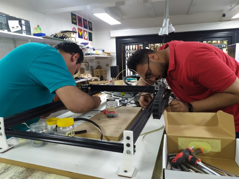
Then I will Hold the Z-AXE on the Chasis

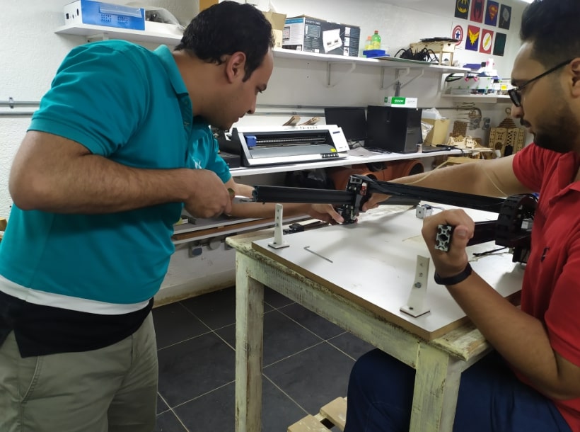
And Now for the Last Part of the Assembly is To connect the Arduino with wires

Noha's Work
And here is our Lovely Noha's Work
I recommend to Visit Her Website and see her cool stuff
Introduction
Almost all CNC machines have a single function per machine, despite that they may have the same design. In addition, the commercial solutions for a universal CNC machine are relatively expensive. In this project we will design and build an inexpensive CNC machine that could have many different attachments, all while controlled through a simple interface of G-code. The machine can perform milling and laser engraving operations. We wanted to build this CNC machine as a proof of concept while at the same time create something we could upgrade in the future.
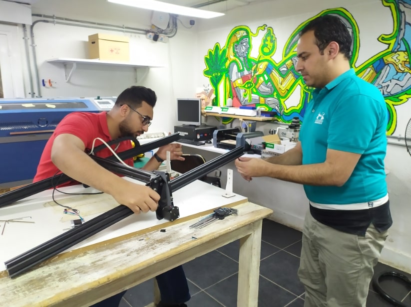
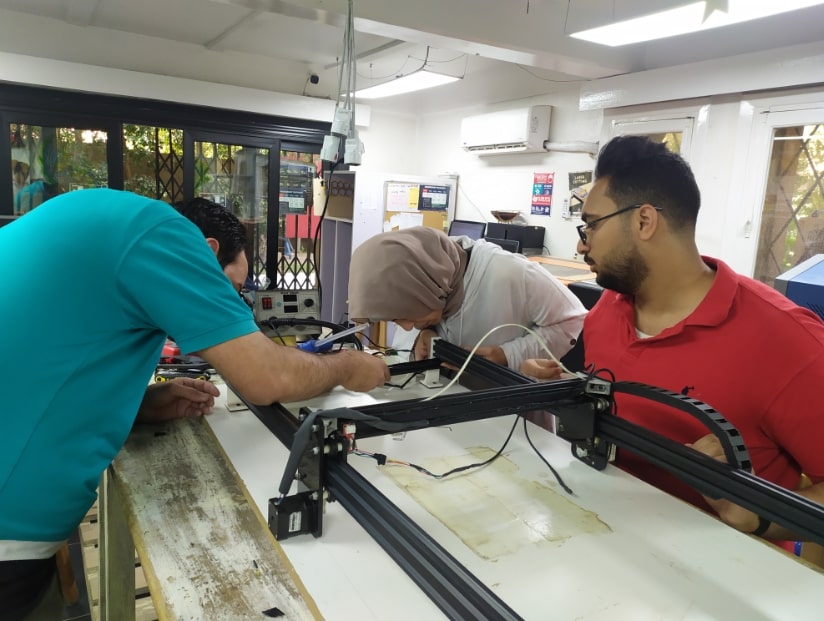
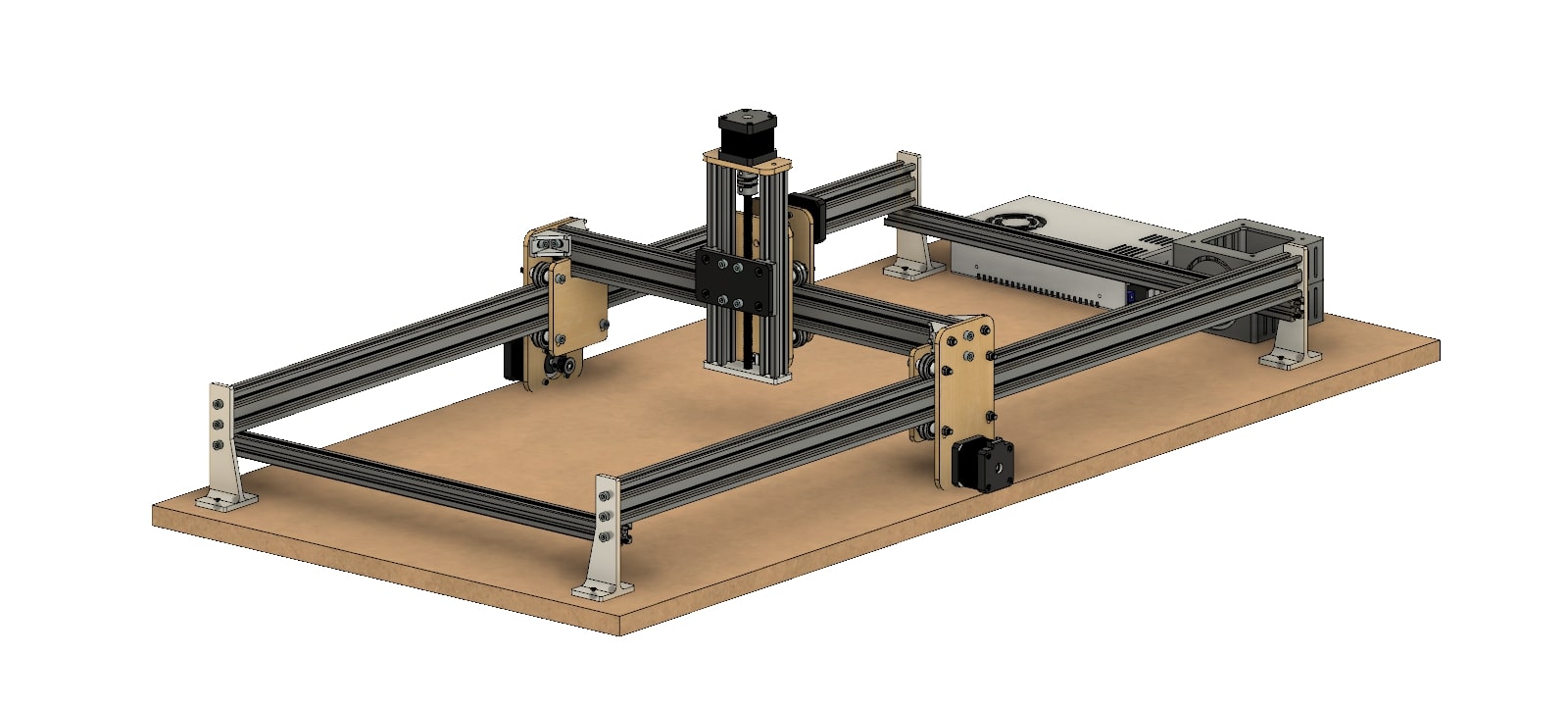
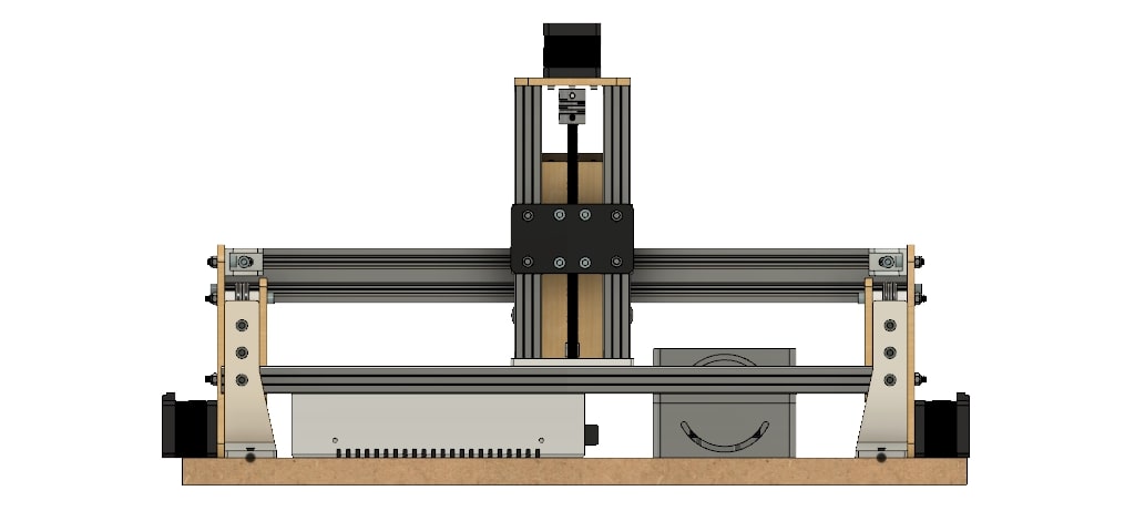
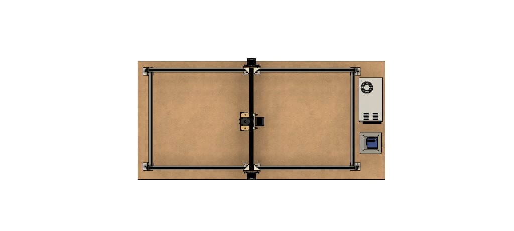
Design
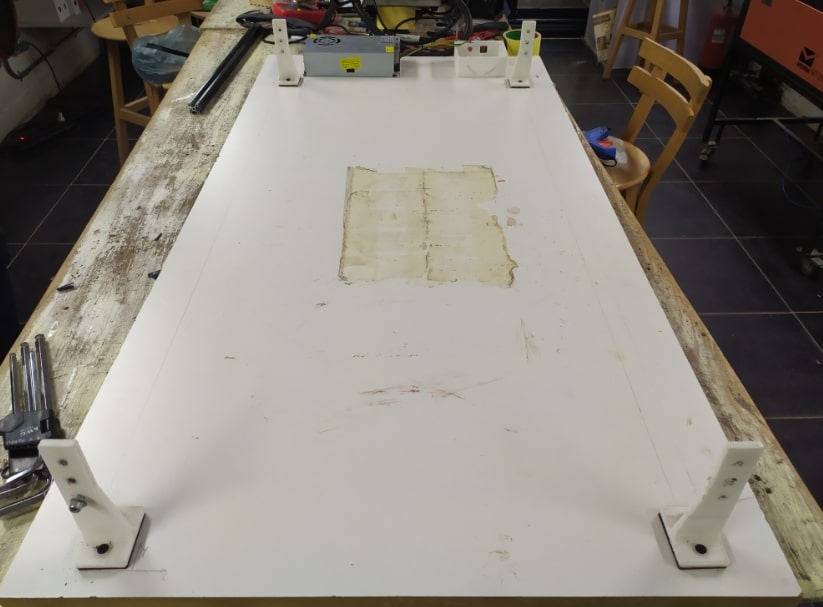
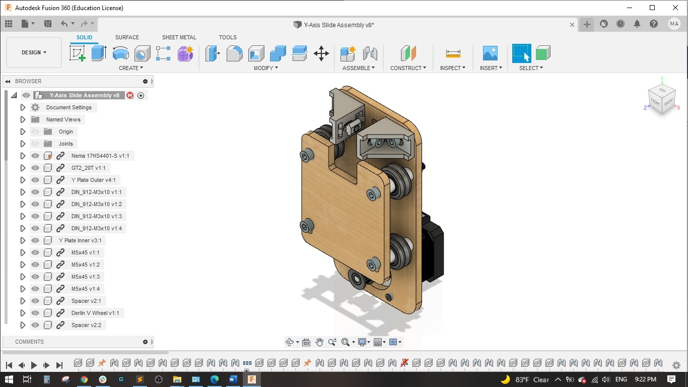
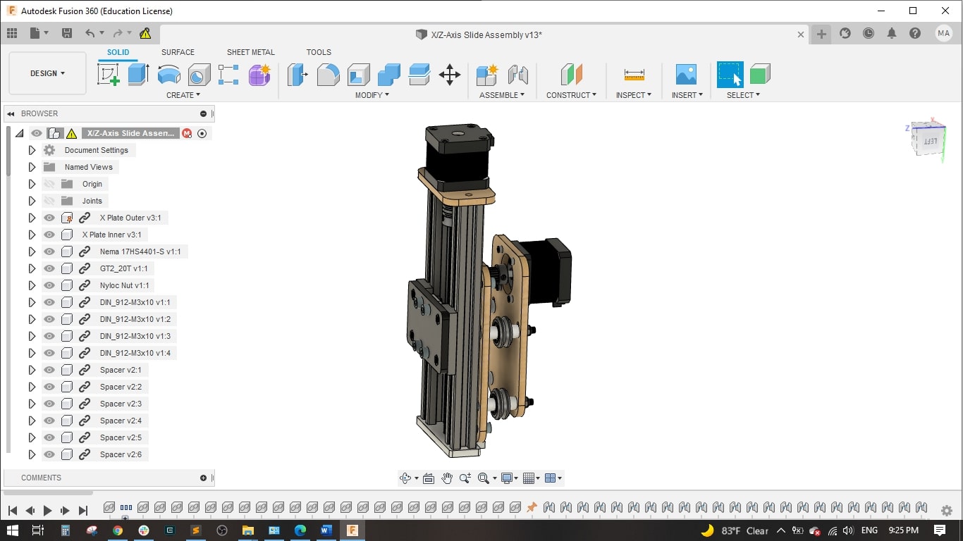
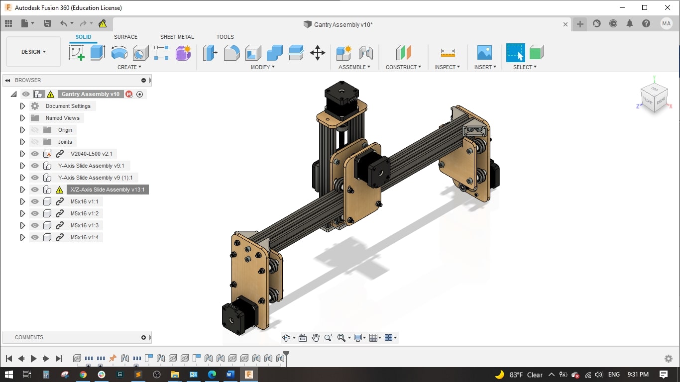
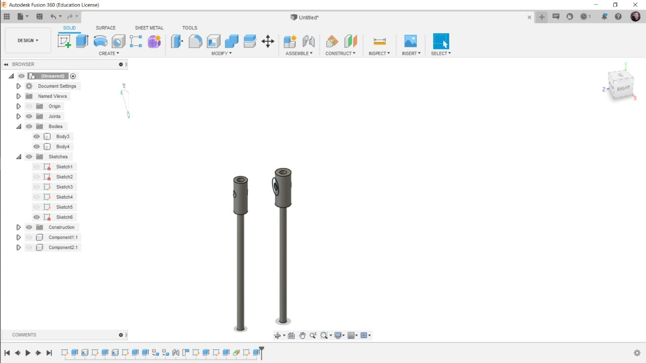
We used AutoDesk Fusion 360 to create my design. The area of travel for the cutting tool is 320 mm in the X, 830 mm in the Y and 120 mm in the Z, but this could be increased if longer aluminum extrusions were used. The work piece itself is fixed on the waste board below the machine. The gantry moves along the Y-axis via belt drive with motors on either side of the frame. The X-axis moves perpendicular to the Y-axis along the gantry, also via belt drive. Attached to the X-axis is the Z-axis, which moves up and down via screw drive. The overall design is similar to the X-Carve mixed with the Open Builds Acro laser cutting system. Again, the goal of the machine is to allow it to be upgraded later on. This means the extrusions can be scaled up or down to fit your needs and budget. We have also designed the Z-axis to have a basic attachment scheme, meaning multiple tools can be attached so long as an adapter is designed with matching mounting holes. For my purpose, we’ve created an attachment for the Dremel and 2.5W laser. You could also design an adapter for a pen or even a 3D printer head to name a few options.
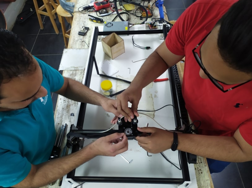
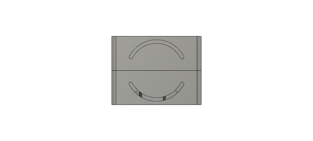
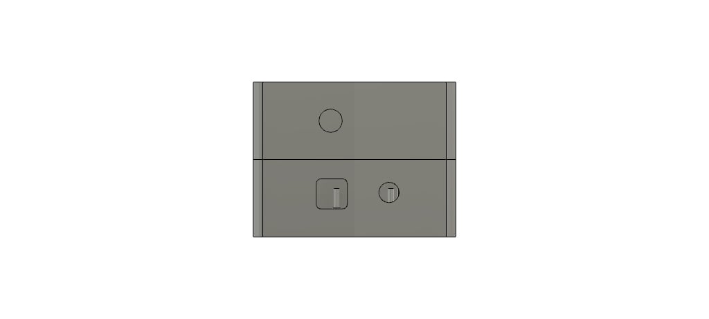
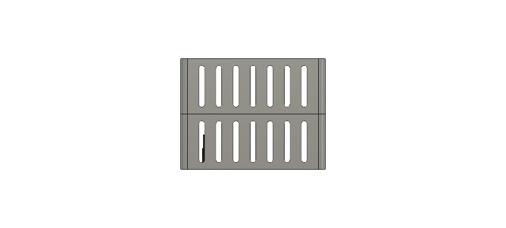
Parts
Y axis
XZ-Axis
Gantry
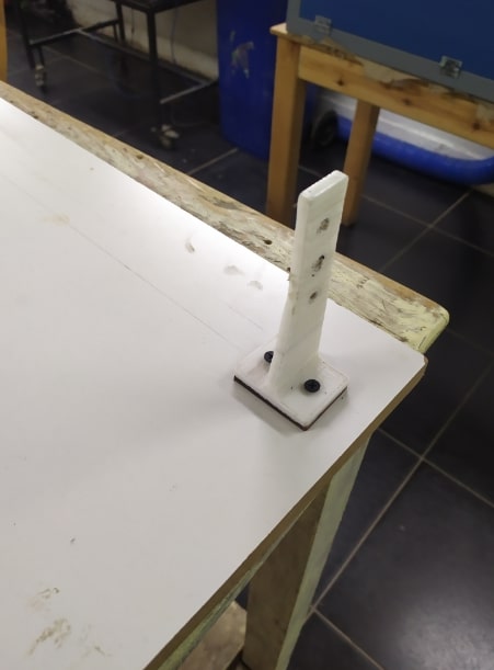
Motor mounts
Abo Elnaga
This Part is about the Electronics and Coding , Here is Abo Elnaga Work, I recommend you to visit his Website and see his wonderful Work
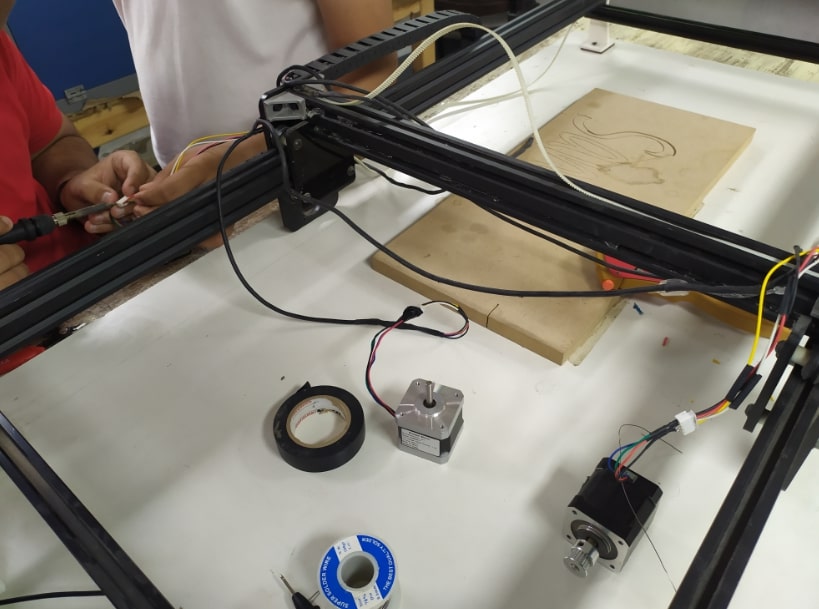
Exploring the electronic components
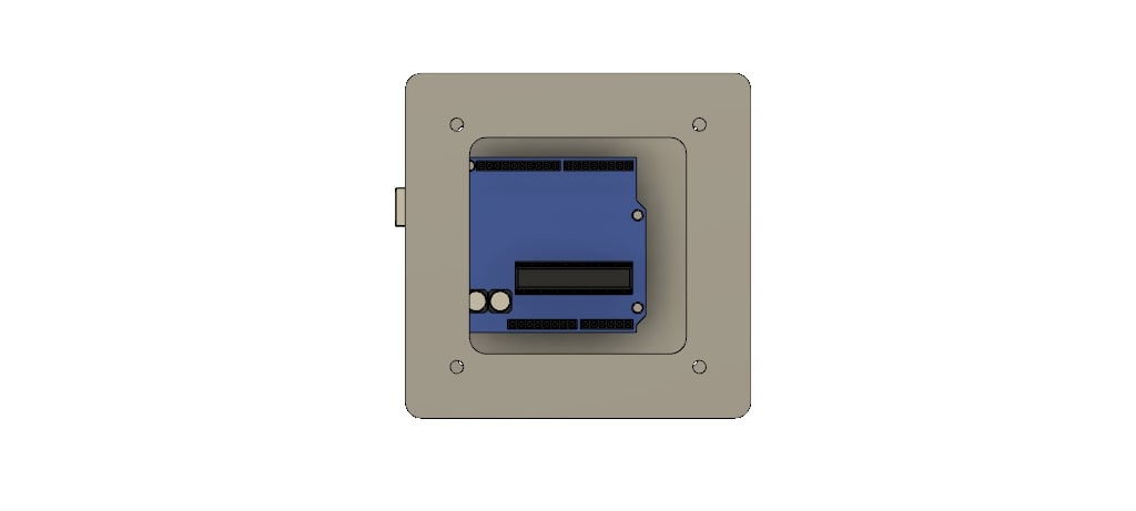
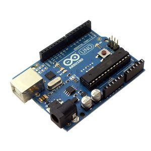
Arduino: is a development board and an integrated development enviroment (IDE), it has a microcontroller to be programmed to do specific functions, and also has some input and output pins to communicate with the enviroment, it can take signals from sensors and then instruct actuators to do some tasks. We will use the Arduino UNO to control the machine.
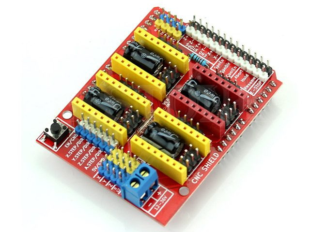
CNC Shield: is a shield which is assembled with the Arduino and has drivers to control the stepper motors. it takes the high power and arduino signals and handle them to the motors.
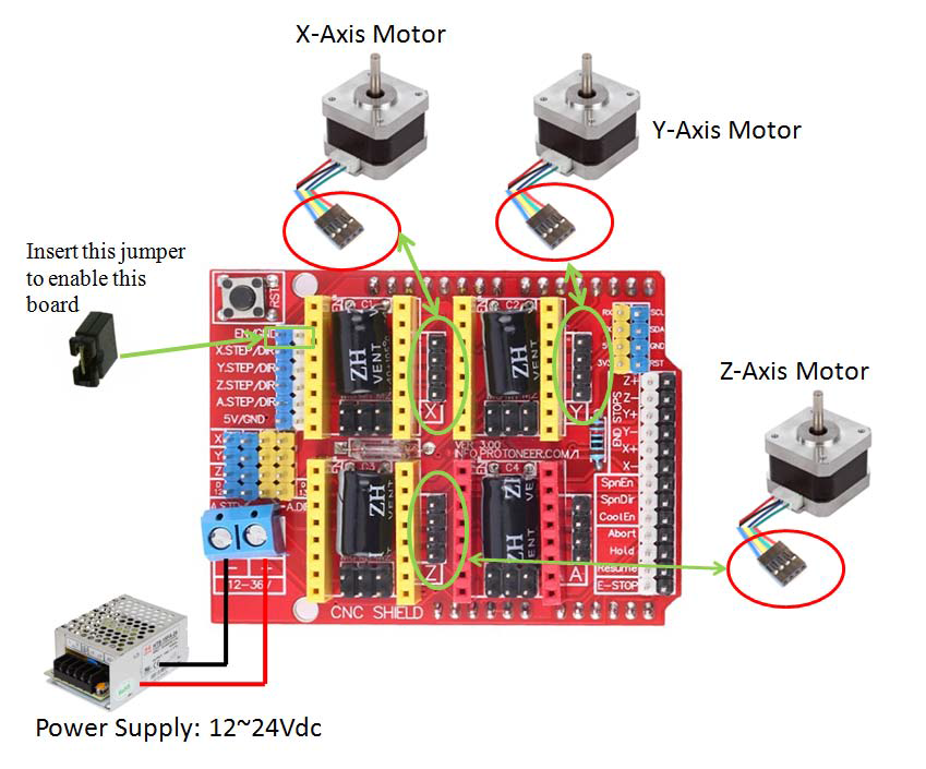
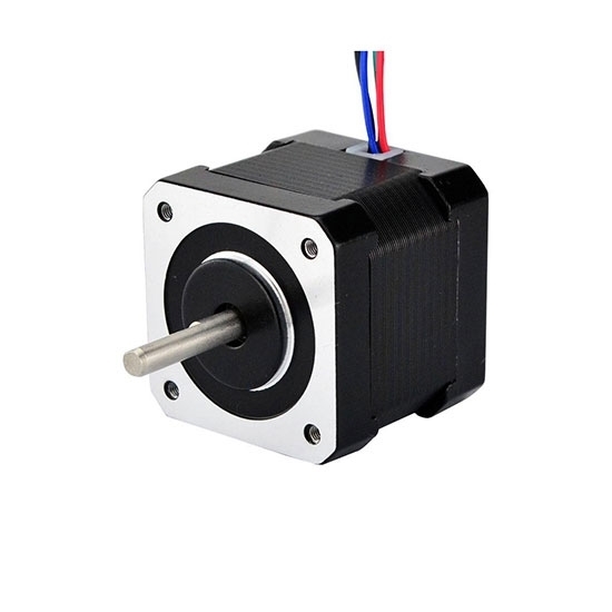
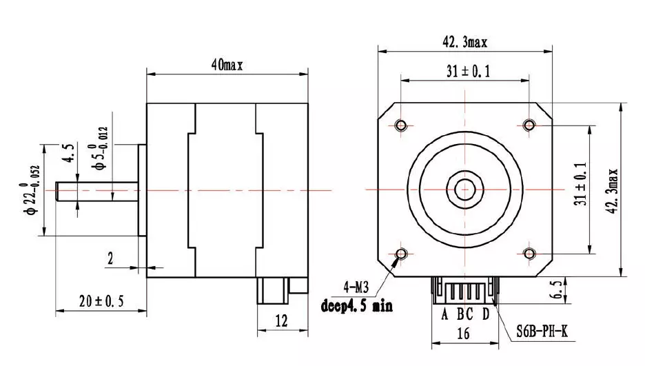
Actuators: they take signals in order to move with specific speeds, directions and accelerations. We will be using stepper motors (NEMA 17 standard). one motor for the x-axis, 2 motors for the y-axis and one motor for the z-axis.
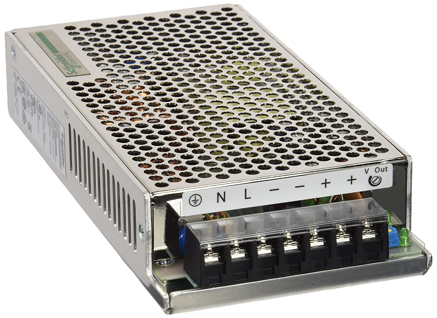
Power Supply: is the source of electricity to power up the machine. it is defined by volt, ampere and power. we are going to use a 24 volt , 10 amp power supply.
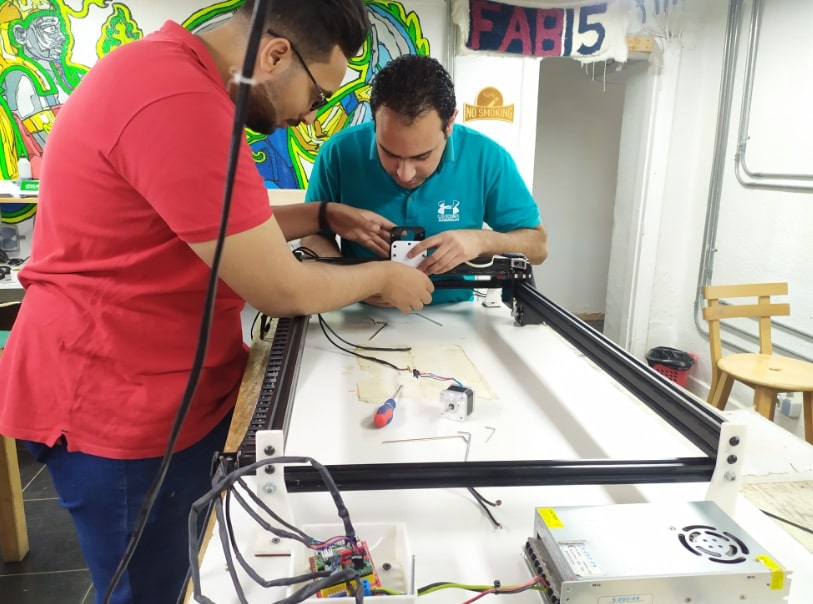
Controling the CNC machine
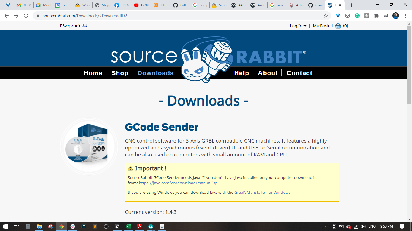
The next step is to load GRBL onto the Arduino Uno as this is what communicates with the motors and transmits the G-Code to the CNC. I placed the motor shield on top of the Arduino Uno and the motor drivers on top of that. It’s best to test one motor and motor driver at a time to ensure GRBL is running correctly. Once you’ve determined GRBL works, you can hook up the rest of the motors and play with them. I thought this step was pretty cool as it’s one of the main things that makes a CNC a CNC. There are various programs online to actually send GCode to the Arduino and most of them are pretty light and self explanatory. I like SourceRabbit GCode Sender the best (linked below), but there are several other programs available that you can find with a quick search. I also attached a few guides I used for installing GRBL and other electronic troubleshooting;
At this point you can also use the jumpers included with the CNC kit for configuring the 4th axis and microstepping. Configuring the 4th axis will tell the shield which axis the motor plugged into the “A” port on the board controls. For this CNC, place two jumpers across the Y pins since the two motors control the Y axis. Microstepping is discussed further in the next step. CAUTION: Make sure the power supply is off when messing with the Arduino and CNC Shield. If you don’t then you run the risk of damaging the motor drivers, the shield or even the Arduino.

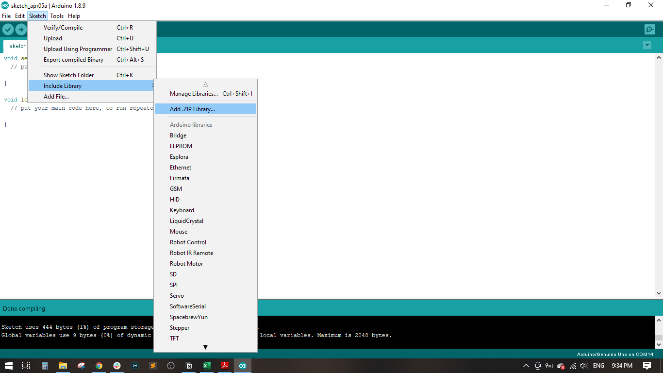


It is importatnt to download and install the Source Rabbit GraalNM to enable java for the software.
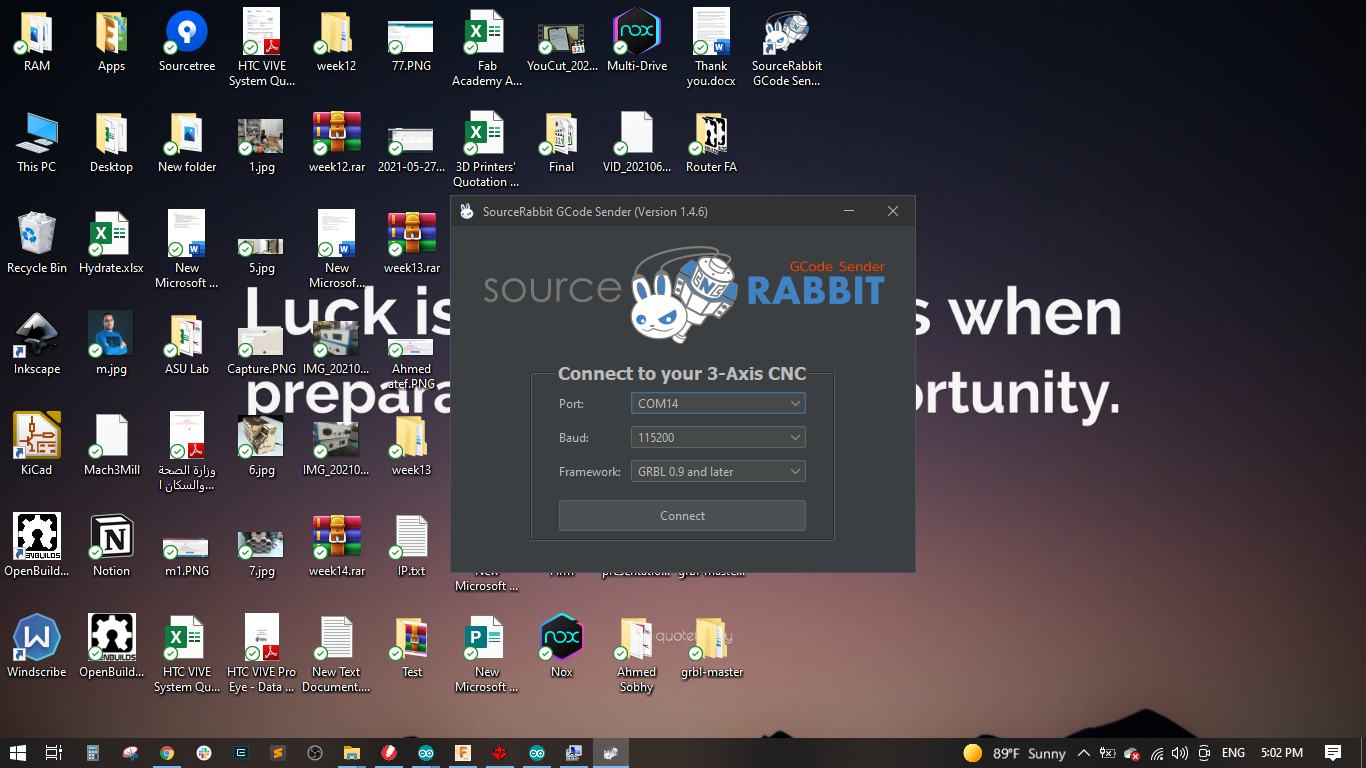
After finishing the installation, I opened the SourceRabbit GCode Sender and selected the port, and baud rate to 115200 and the framework to GRBL 0.9 and later and the pressed connect.
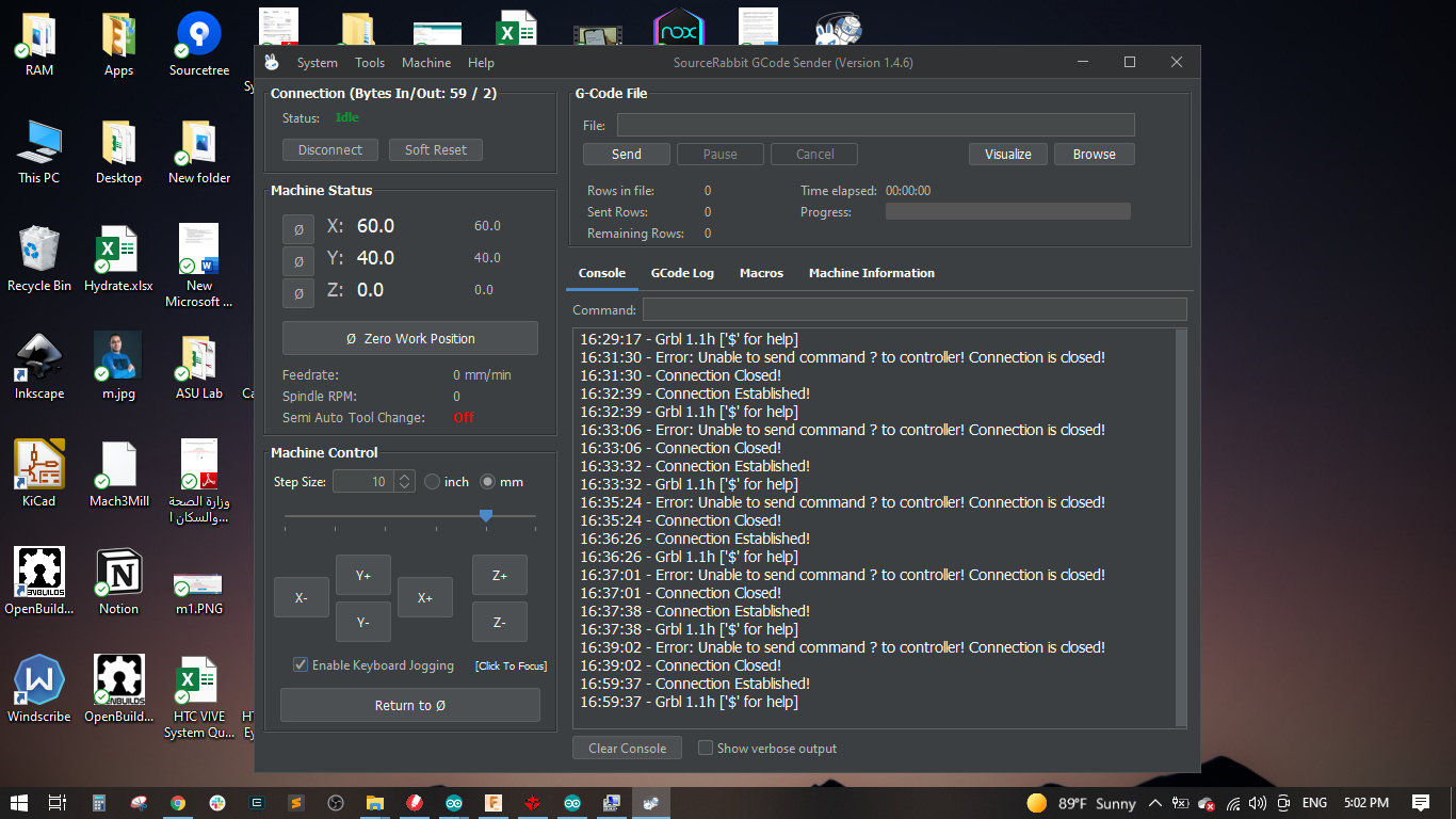
A new window appeared showing the tha macine is conneted, machine status and machine control.
I started moving the motors and the worked well and did some calibration to make sure all motors are working in the correct directions.

Final Videos
Extention Work
Introduction
This is our attempt to design, fabricate and assemble a 2D plotter. The coming sections will describe every aspect of the machine starting with the components, actuators, mechanical design and control.
Electronic component
We used an Arduino UNO with a CNC shield that has stepper drivers integrated on it.
Actuators
We used two stepper motors NEMA17 to control the motion of the machine.

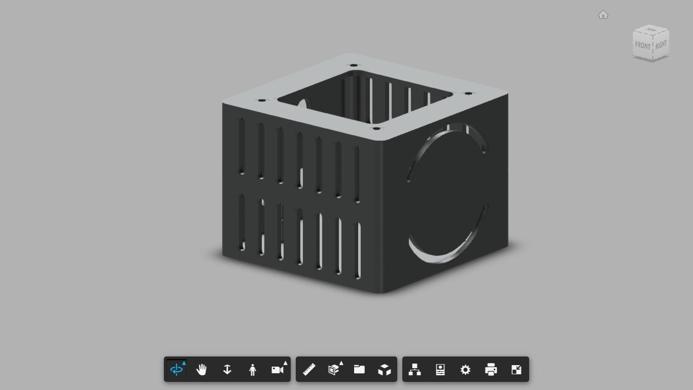
Mechanism
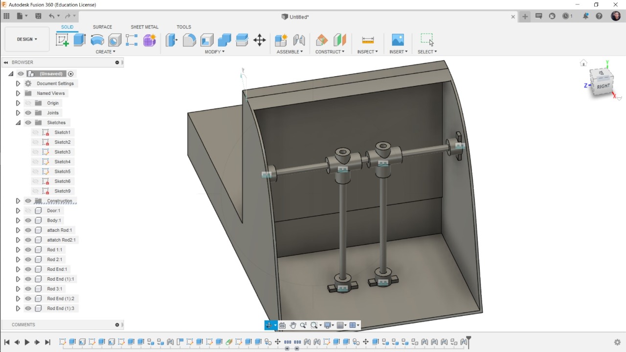

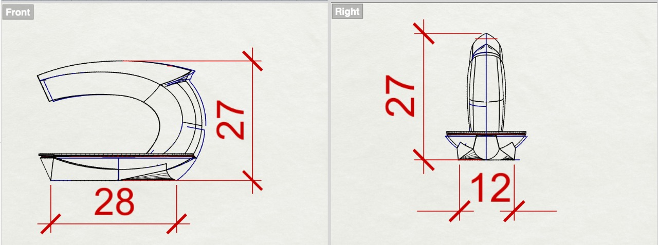
Enclosure
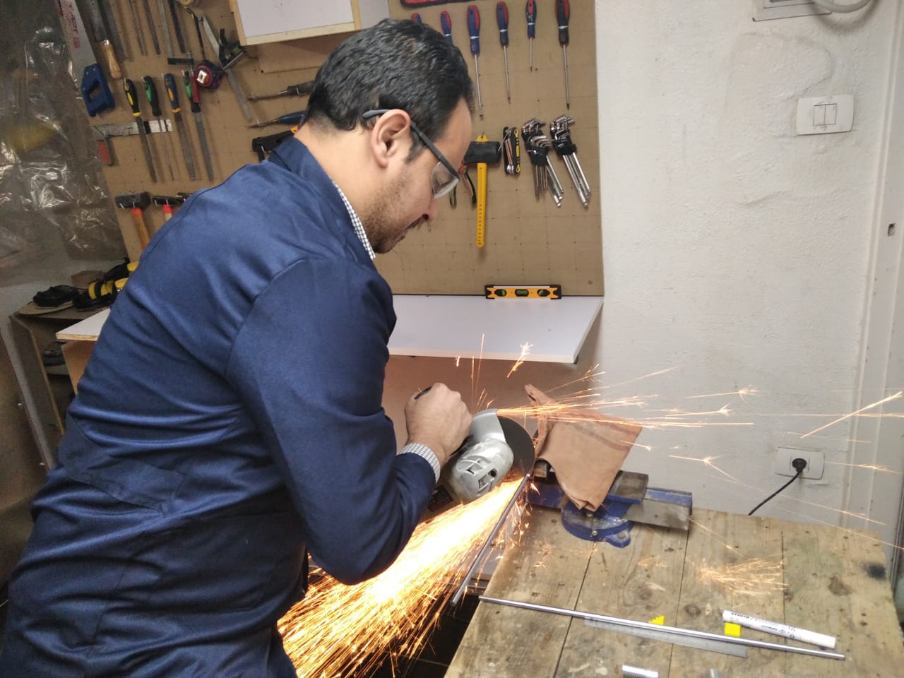
Fabrication
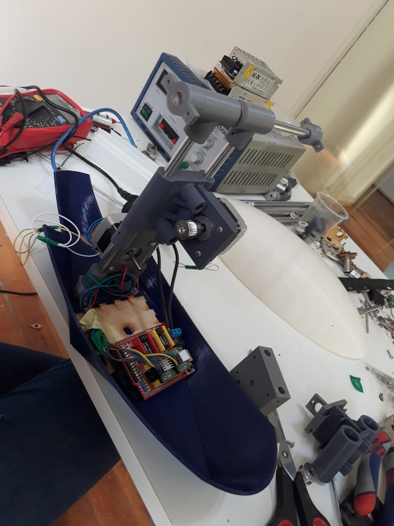
Control
We flashed grbl on the Arduino UNO and used the G-Code sender to send the G-code to the machine.

And We Still Work on it, We have some Issue in Mechanism but I think we will get over it