- Group Assignment:
- Use the test equipment in your lab to observe the operation of a microcontroller circuit board
- Individual Assignment:
- redraw an echo hello-world board,
- add (at least) a button and LED (with current-limiting resistor)
- check the design rules, make it, and test it
- extra credit: simulate its operation
- Link to the group assignment page
- Document what I have learned in electronics design
- Explaine problems and how I fixed them
- Include original design files (Eagle, KiCad, - whatever)
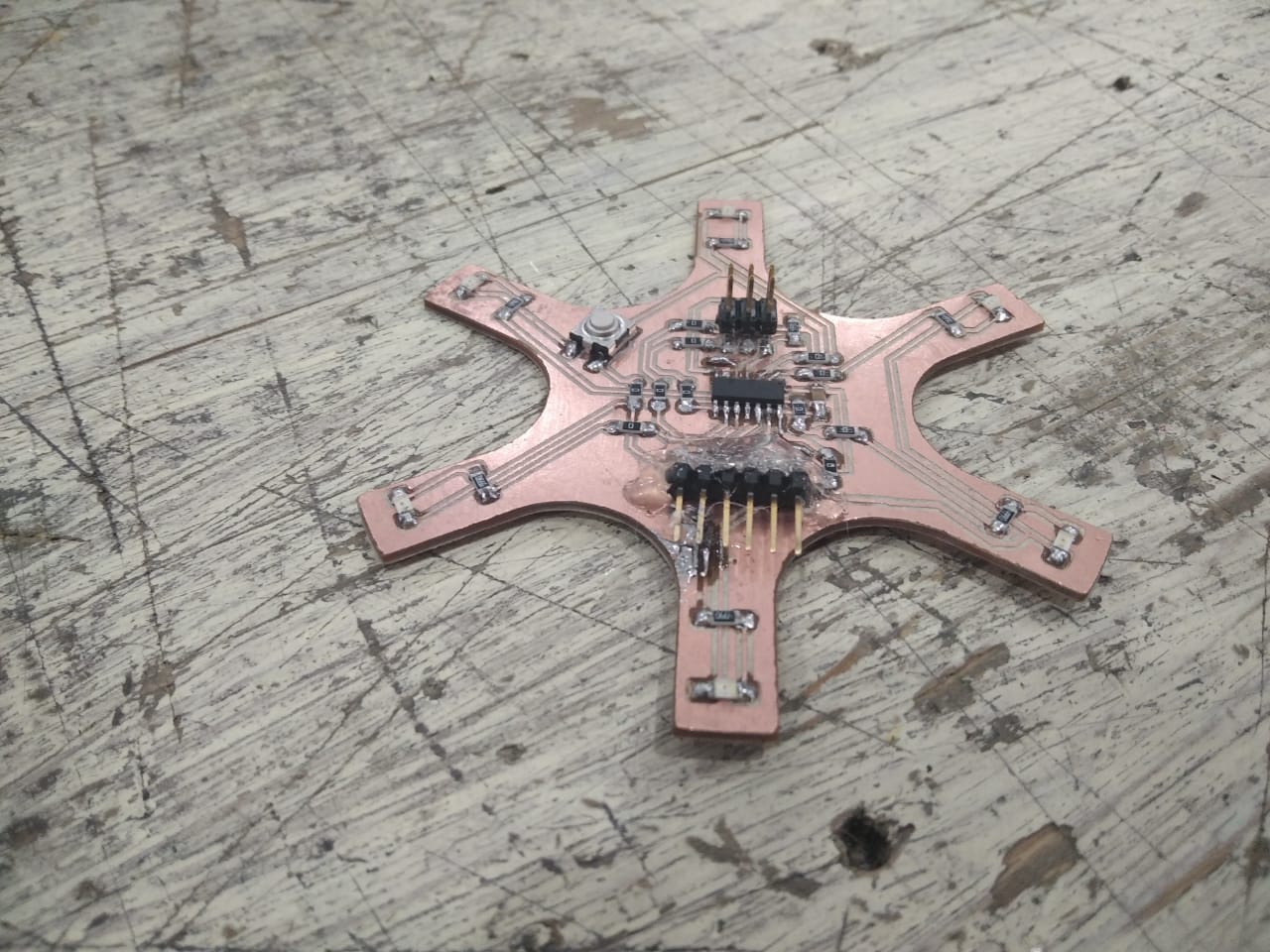
- Include a ‘hero shot’ of my board
- Load a program and test if my board works
Roland:MDX-20 FabModules KiCad Photoshop Arduino
Group Assignment
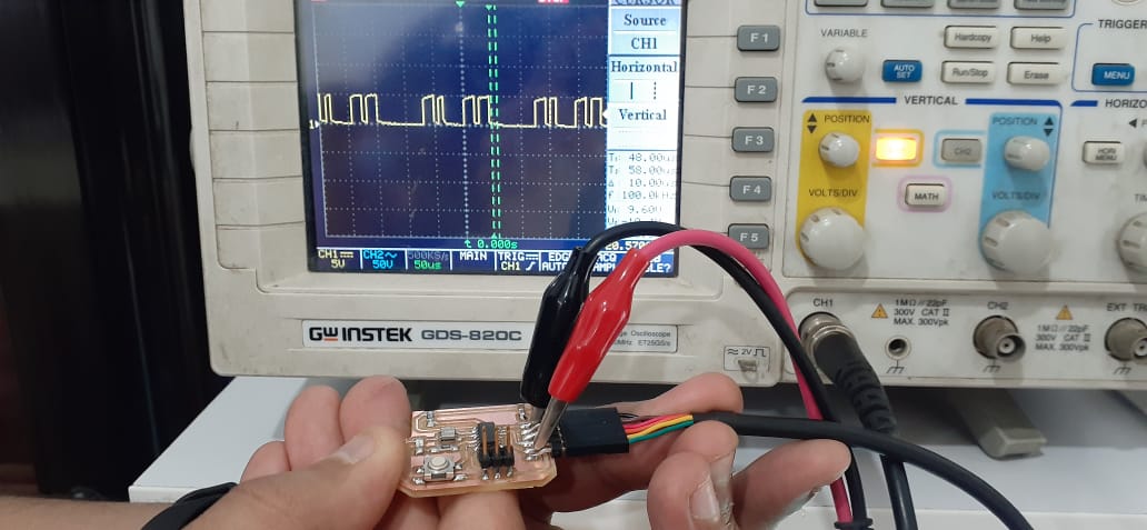
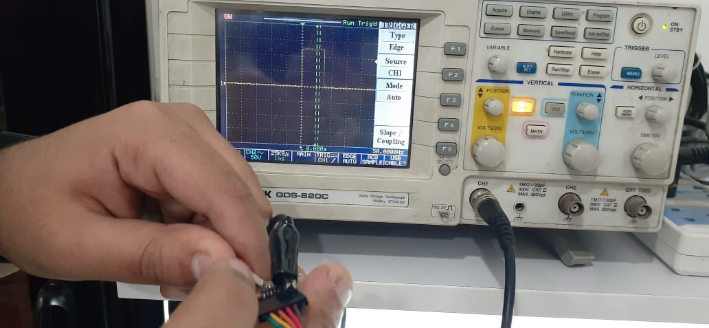
UART
The board is programmed to continously send a character to the computer. We connected the TX pin to the oscilliscope to observe the waveform of the communication. The image below shows the observed waveform.
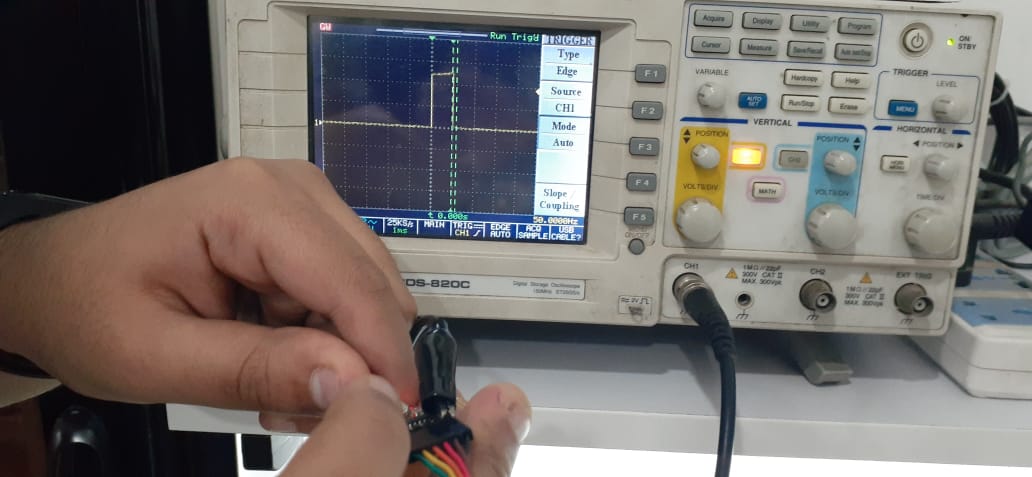
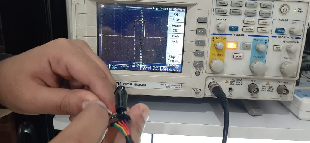
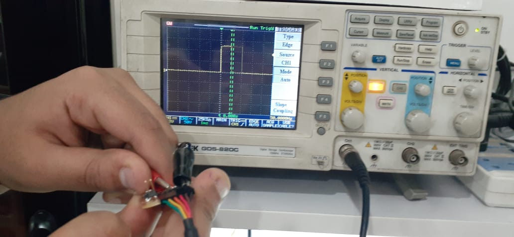
PWM
The board is programmed to generate a PWM signal for controlling a servo motor. The pin is hooked to the oscilliscope and the waveform is observed multiple times to see the change in the duty cycle. As shown in the images below, the duty cycle increases as the on time increas
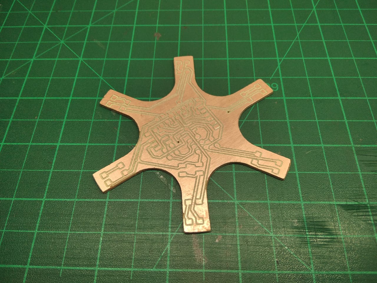
PCB Design
This PCB will be slightly diffrent from other PCBs so Keep Reading carfully
The Component I need
- ATTINY 44
- 6POS 2-Raw Male Header for ISP
- Right-Angle Male Header 0.1" for FTDI
- 10Kohm Pullup Resistor
- LED
- 1uf Bypass/Decoupling Capacitor
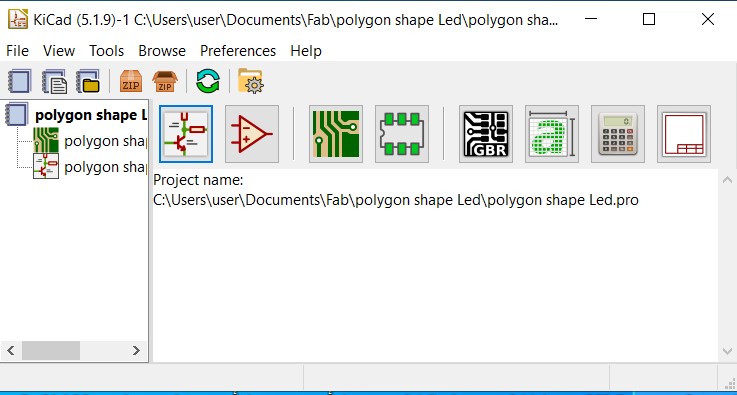
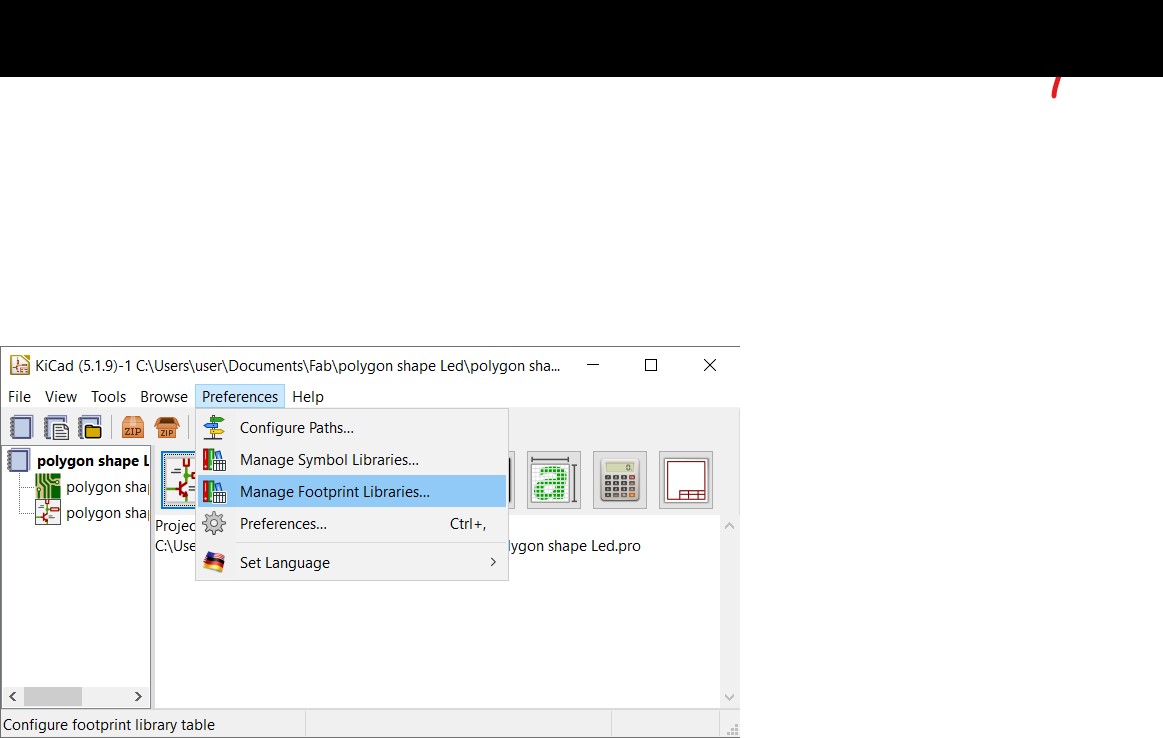
open KiCAd
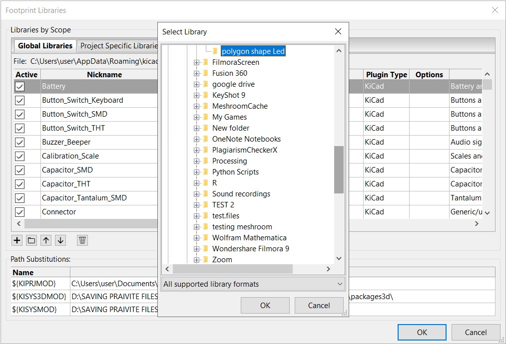
Strat to add Fab modules library
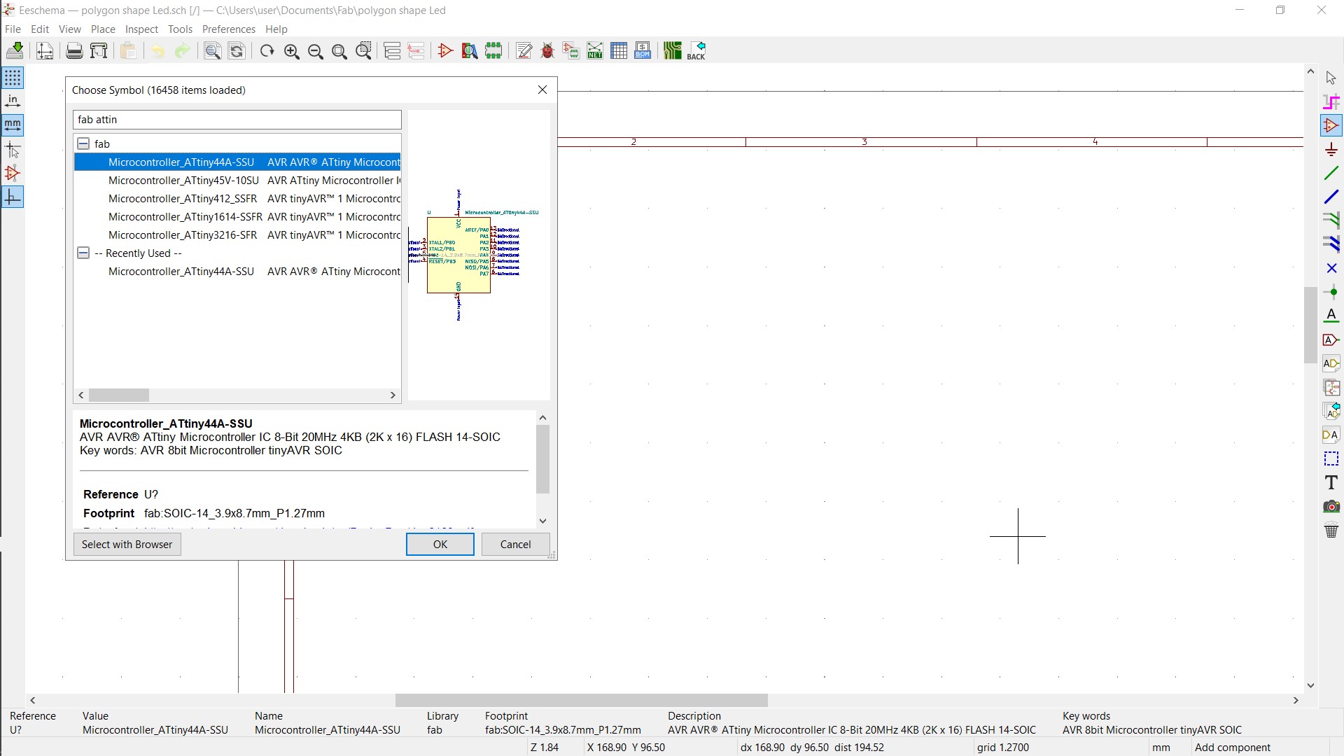
Start to add the Components we need
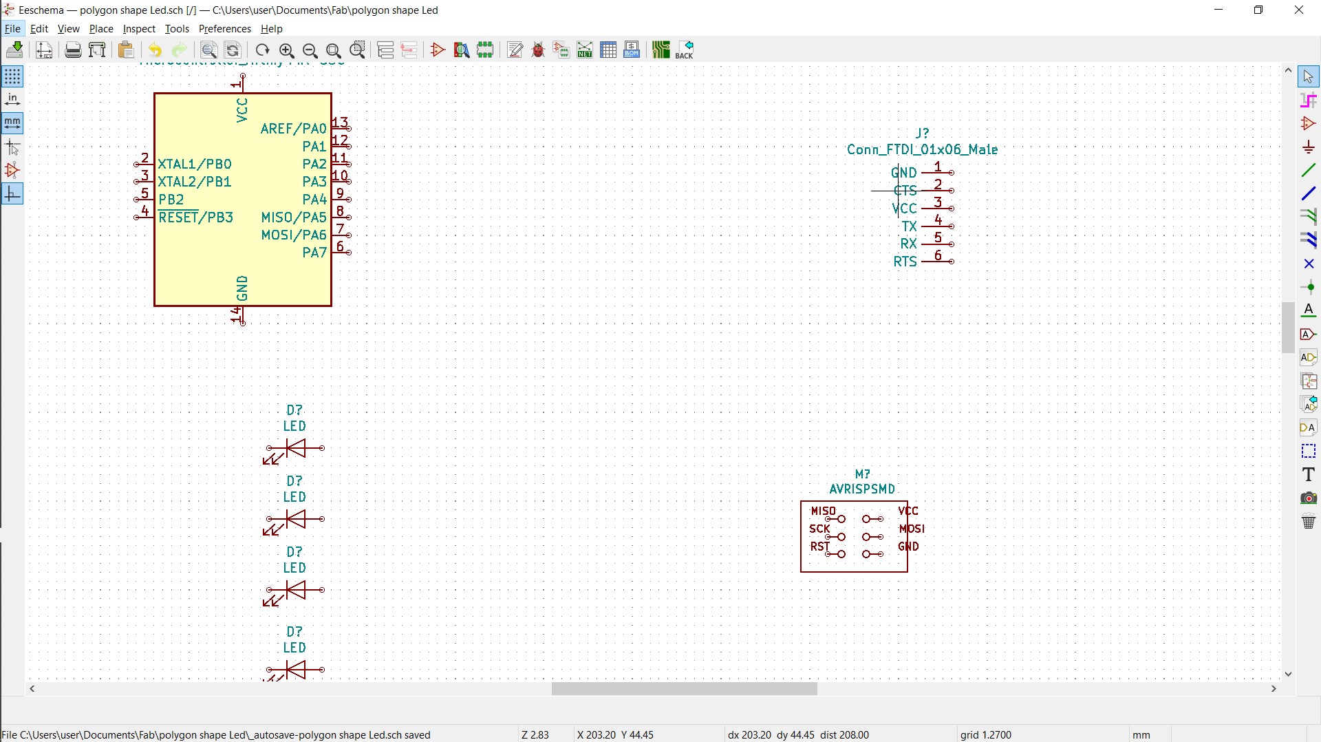
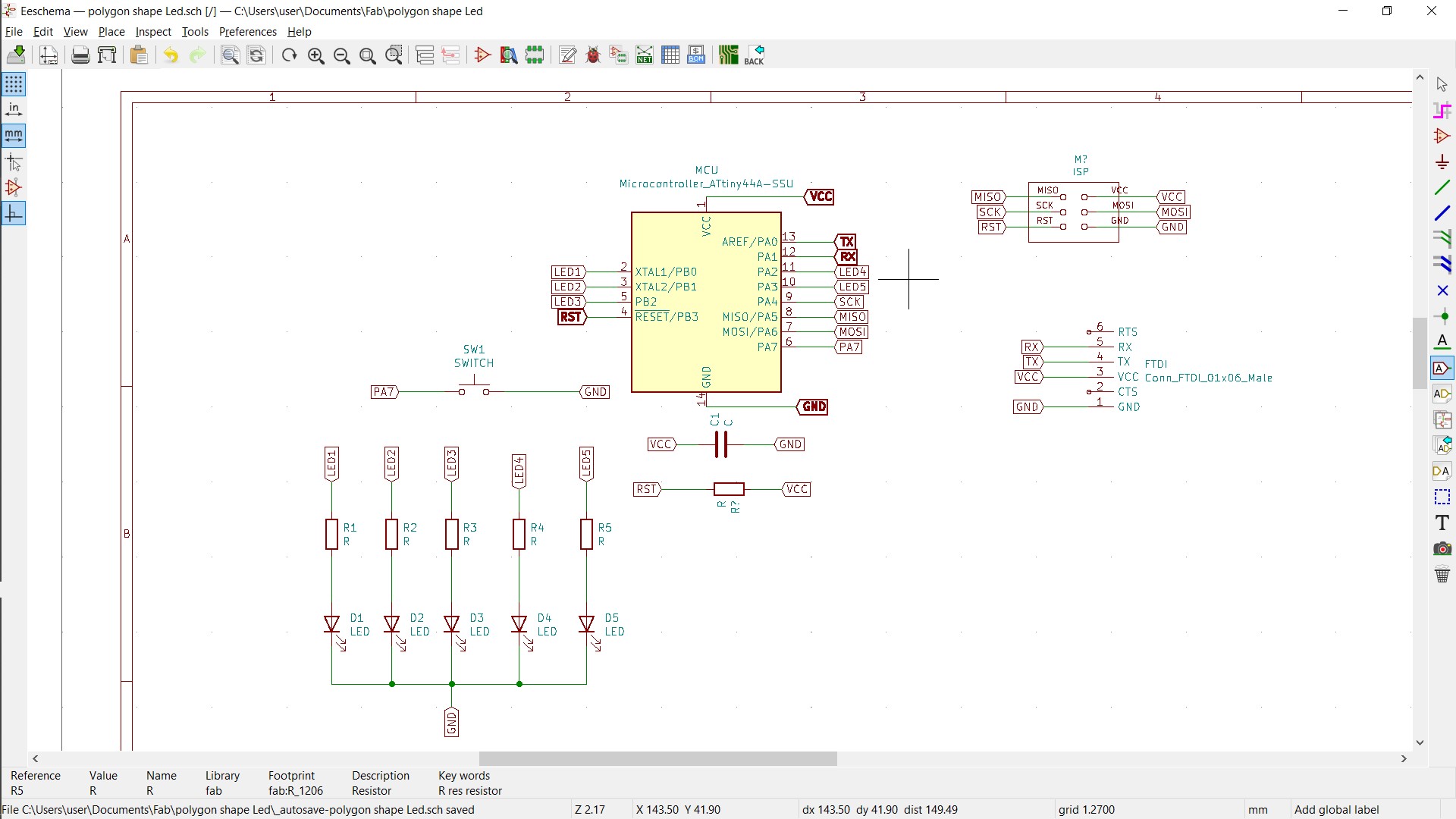
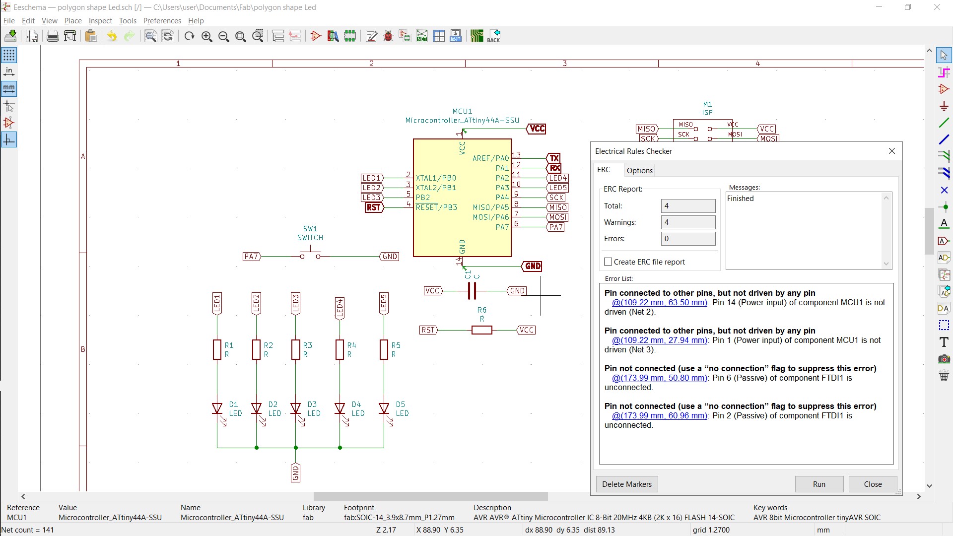
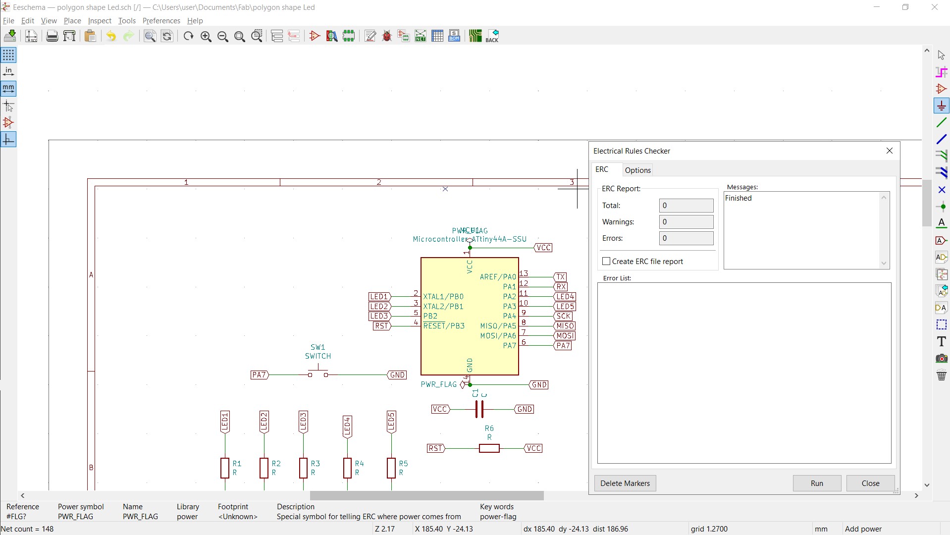
Check the Connections and see if there is an Erorr or not
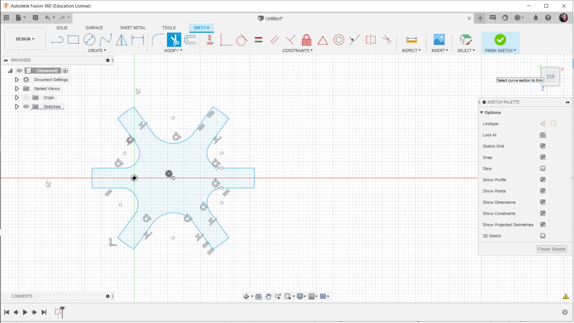
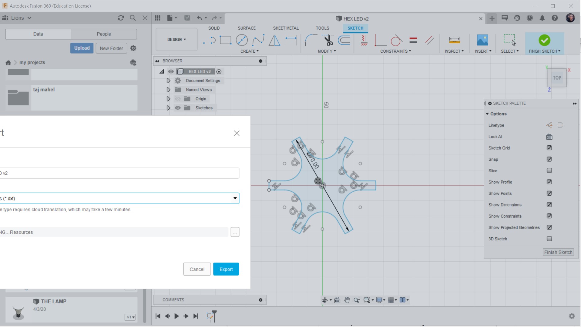
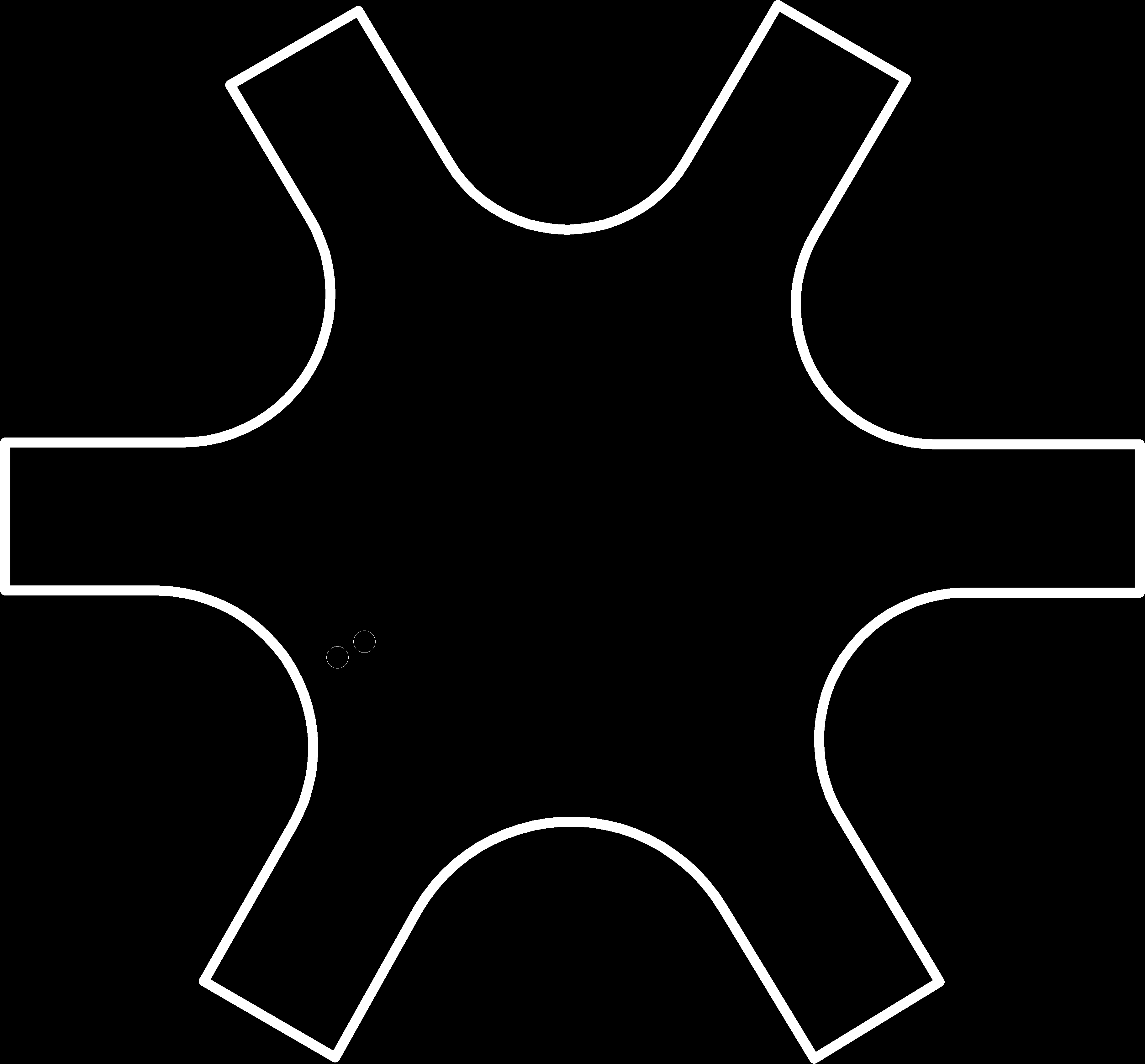
After that Open Fusion 360 and Draw the Shape you like And then Save It as DXF file
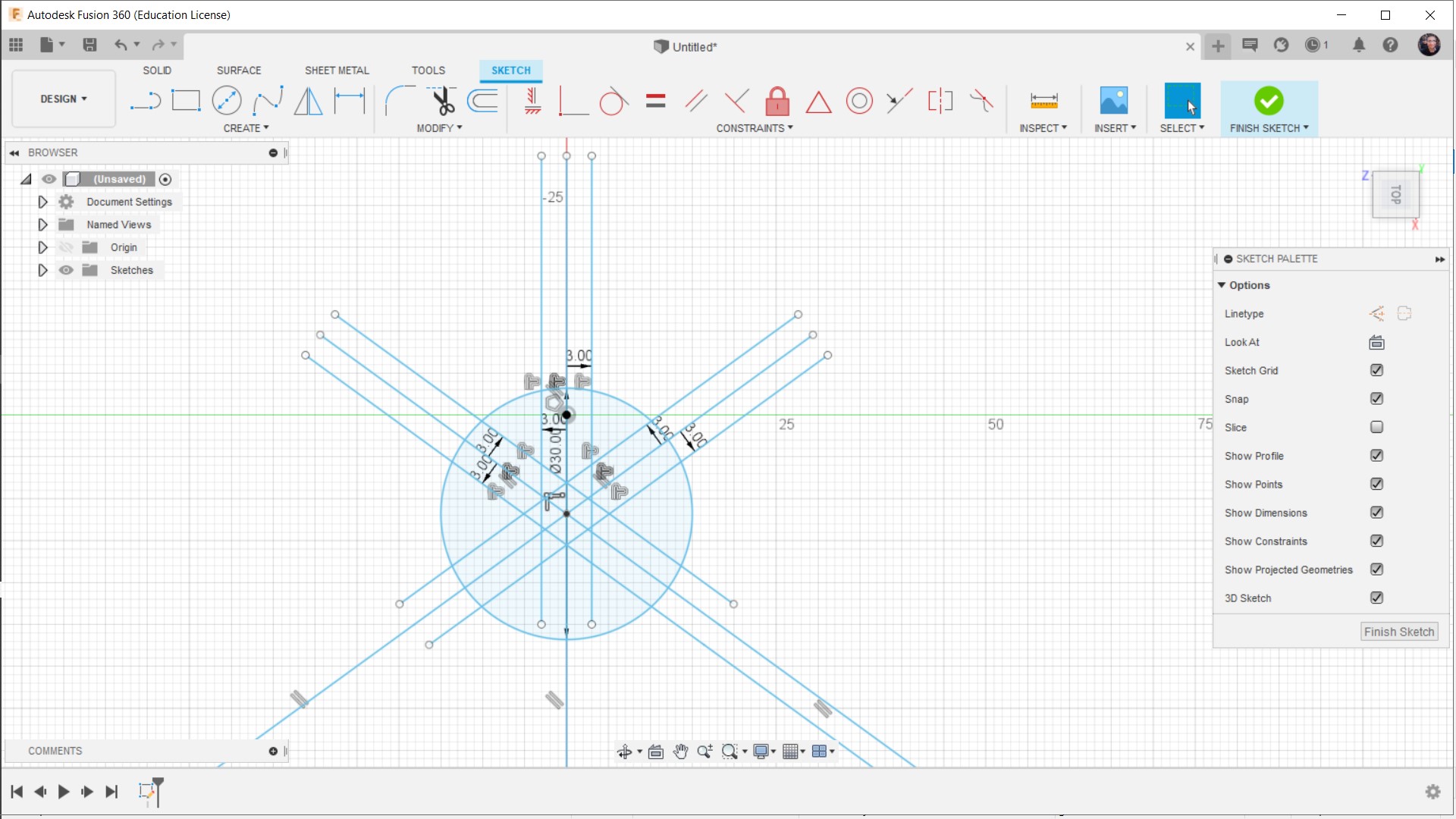
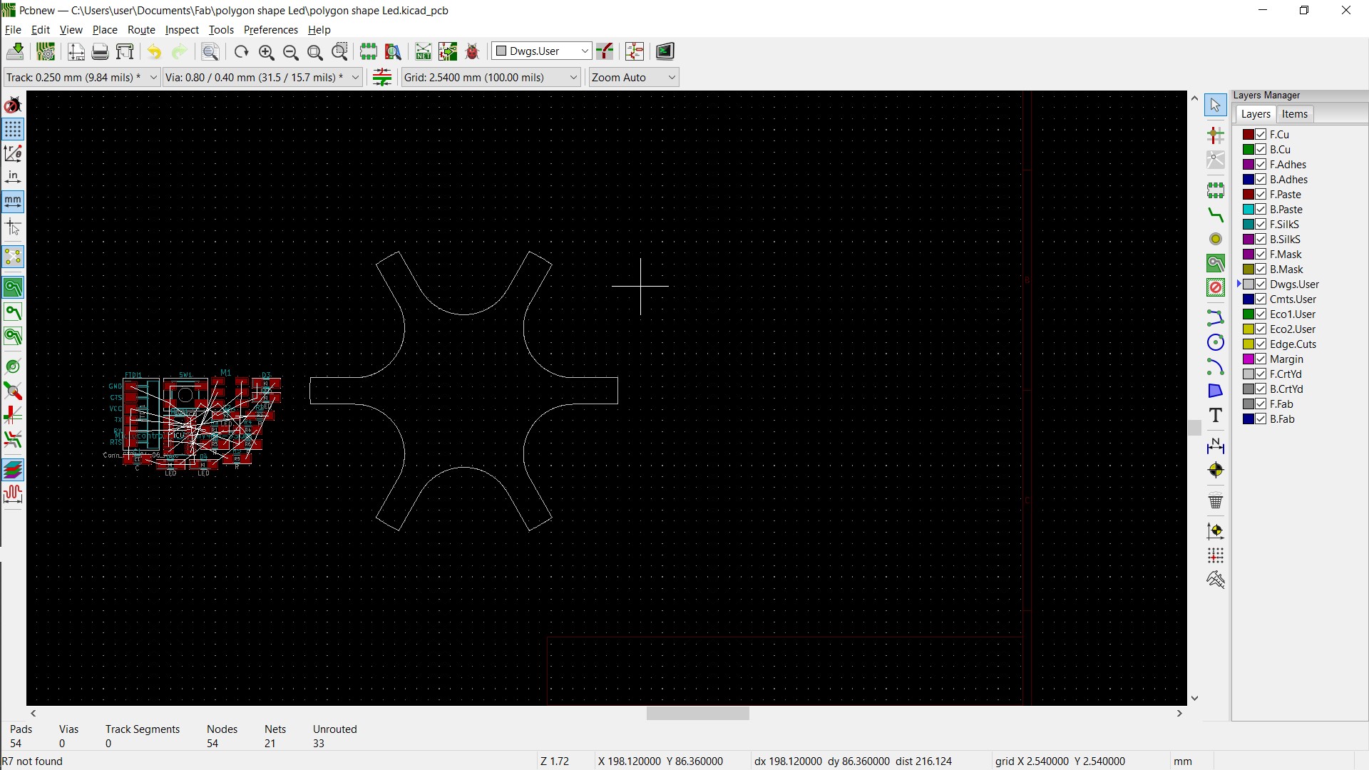
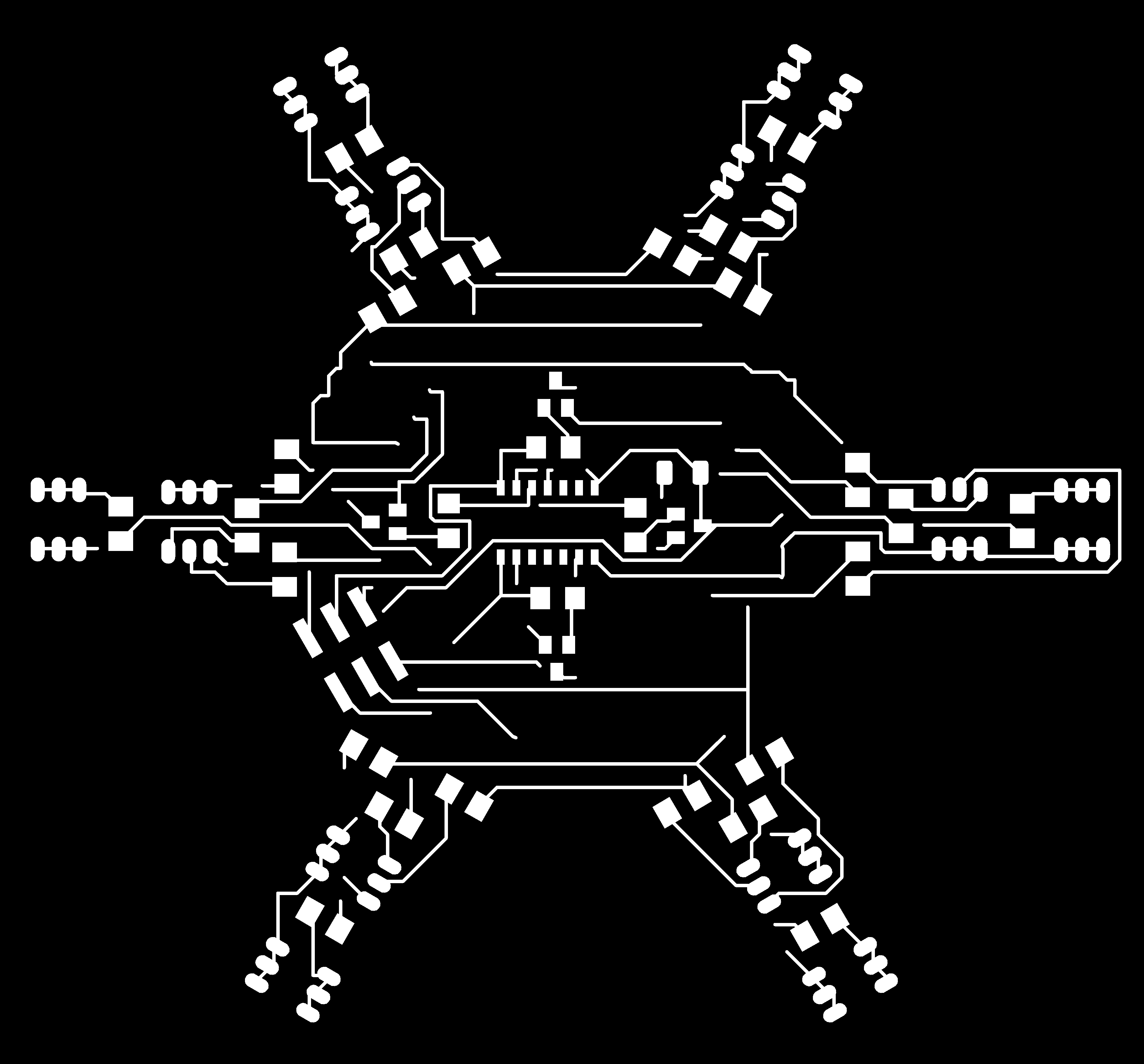
Import the DXF shape to KiCad to make the Connection of the Circuit Inside our shape
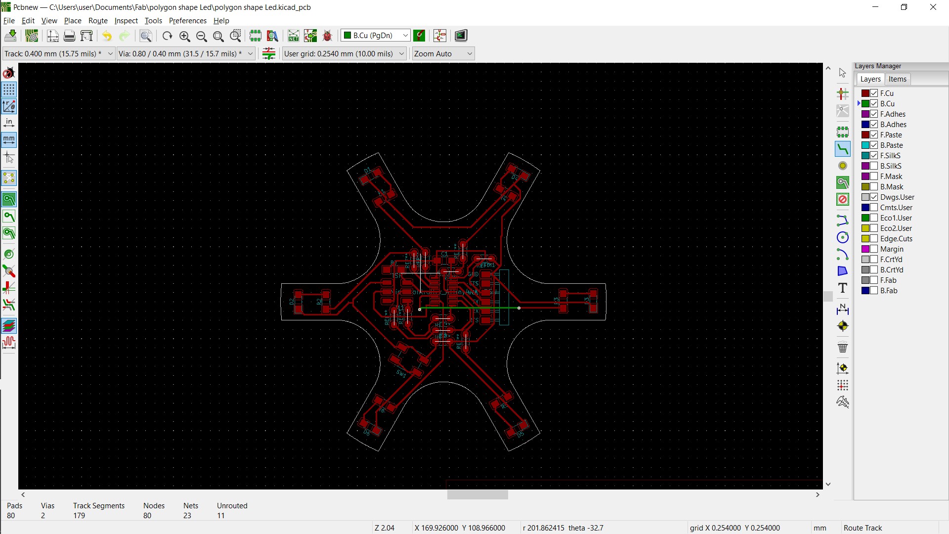
Then Export the Gerper Files
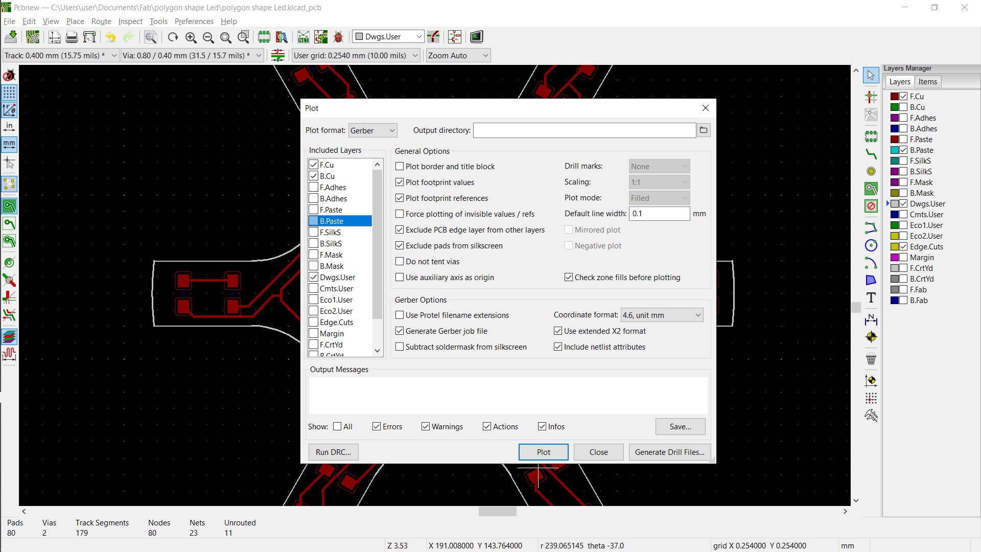
Then after that take the two output images
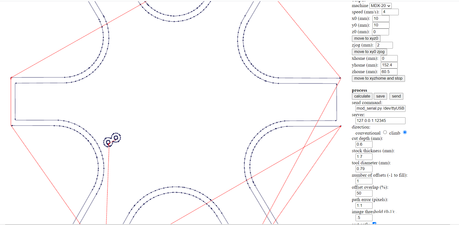
then Open FAB MODULES

Then Upload the Top layer and choose the output (for me it's role and mill)
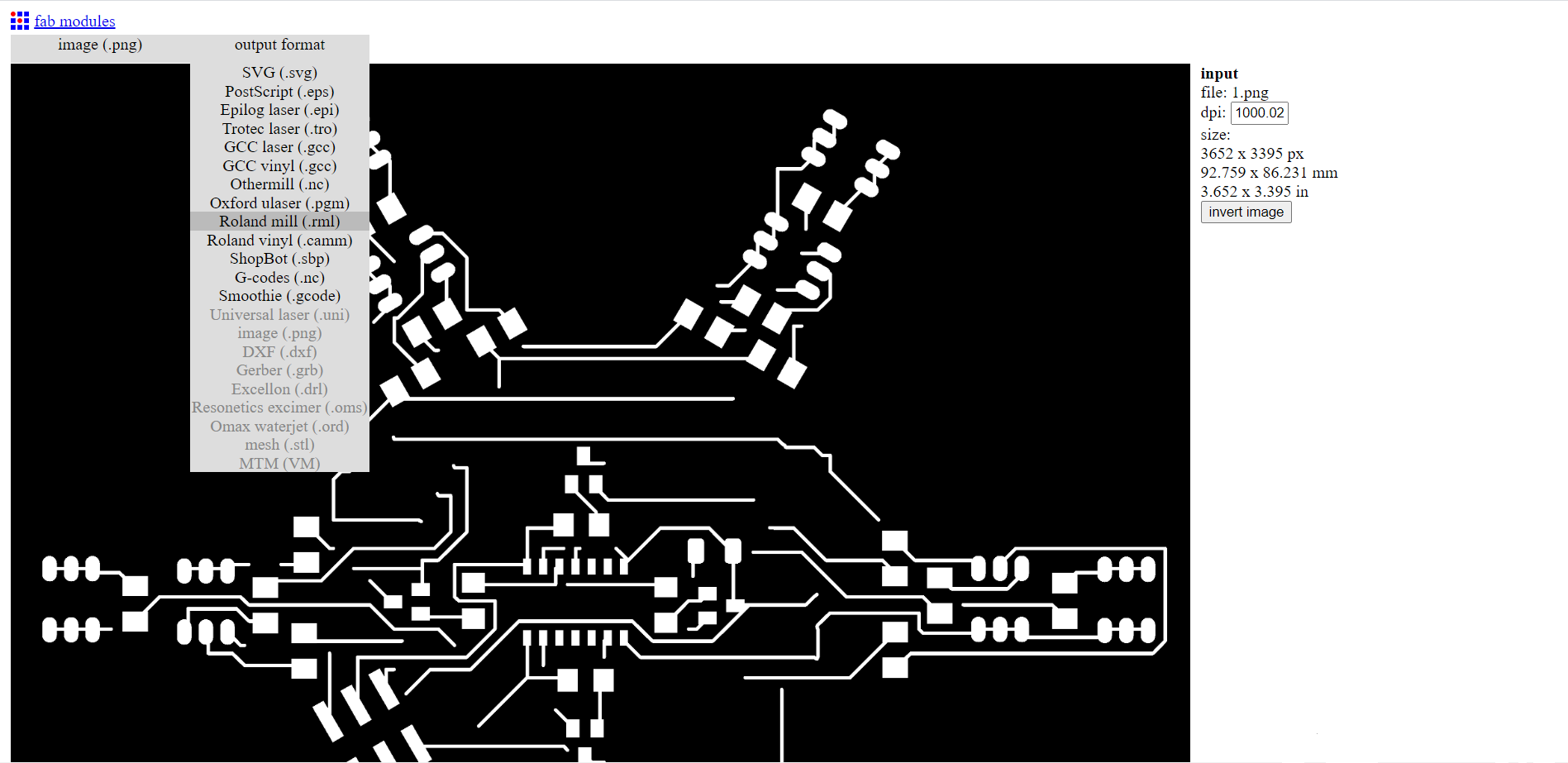
Then Choose the PCB Traces (1/64)
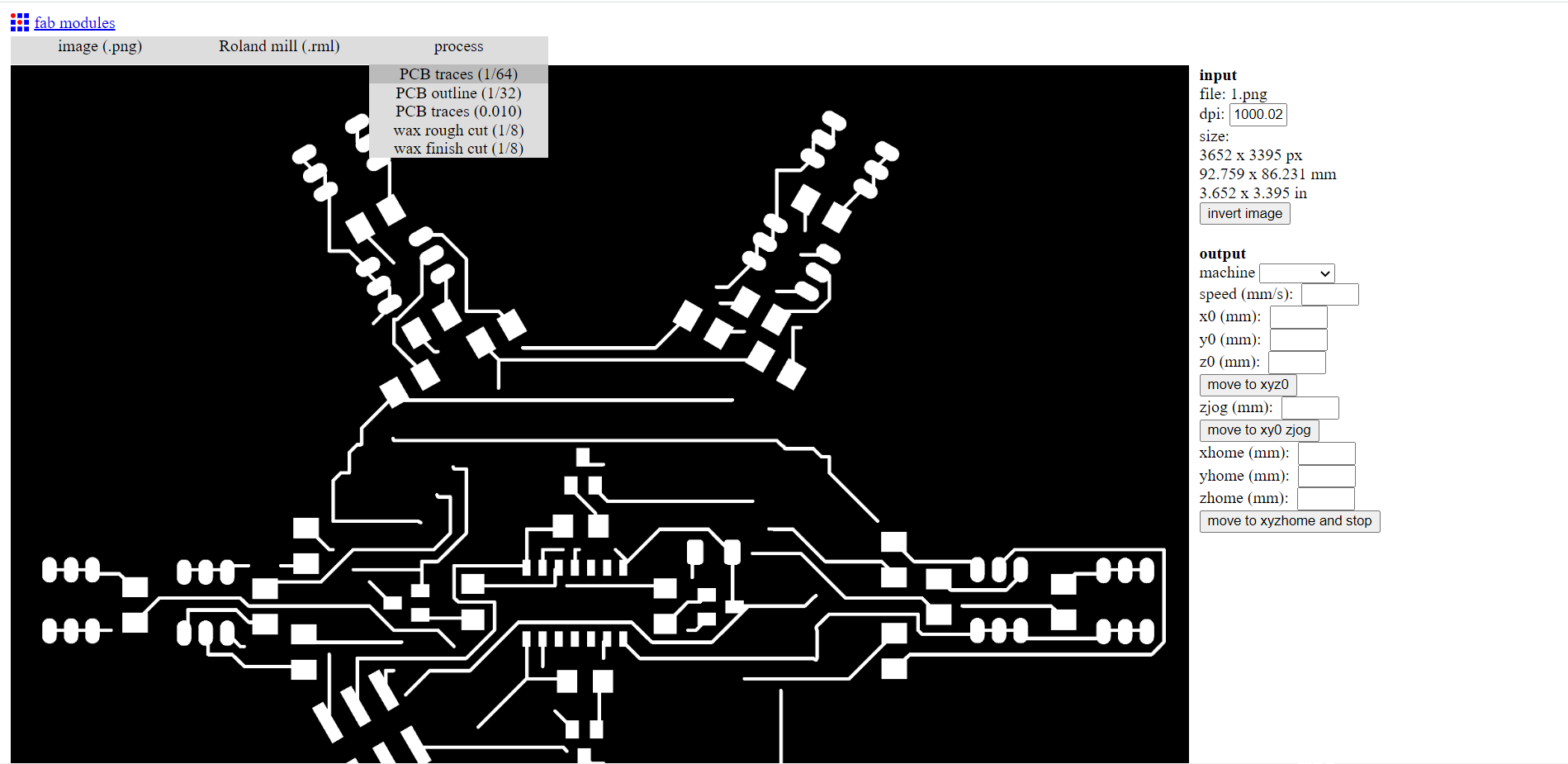
Then make your Prefrences and Press Calculate
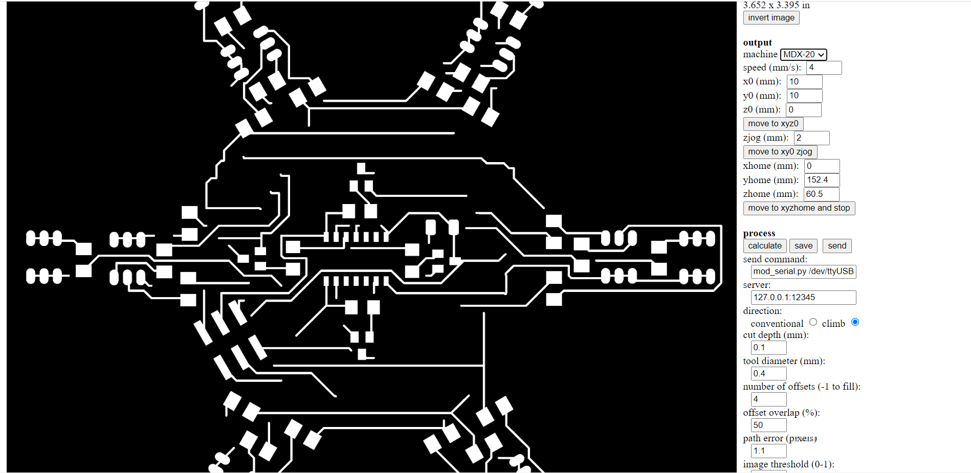
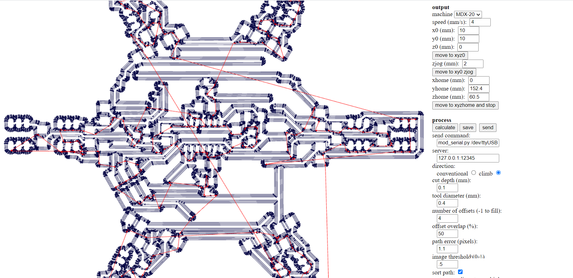
then Send it to the machine
and then make the smae thing at the out line
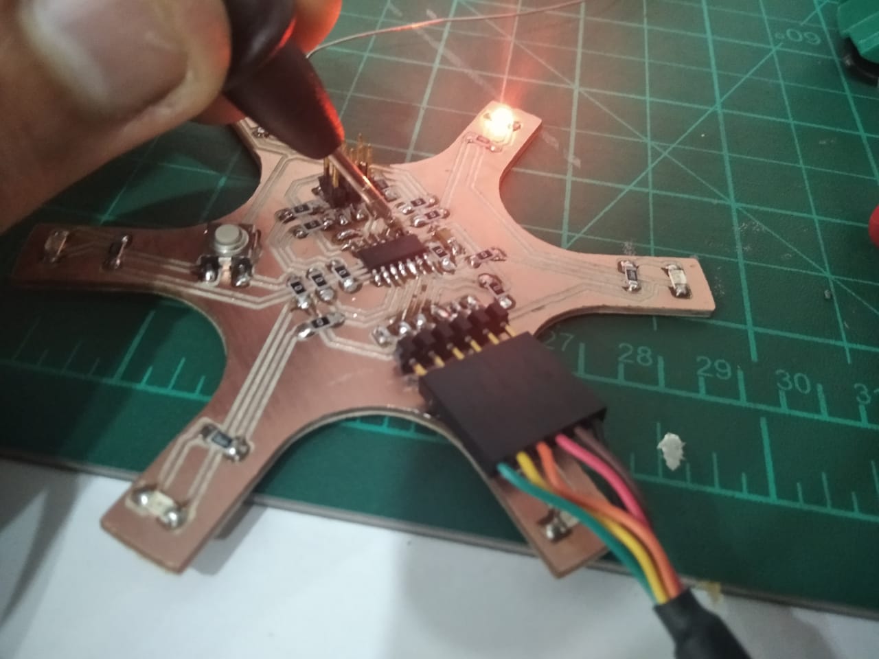
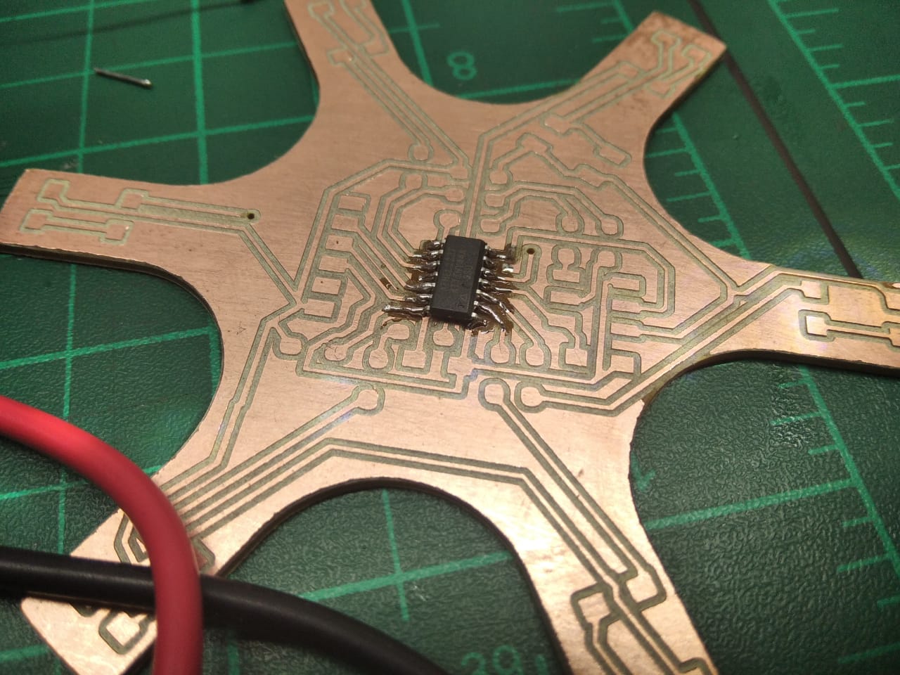
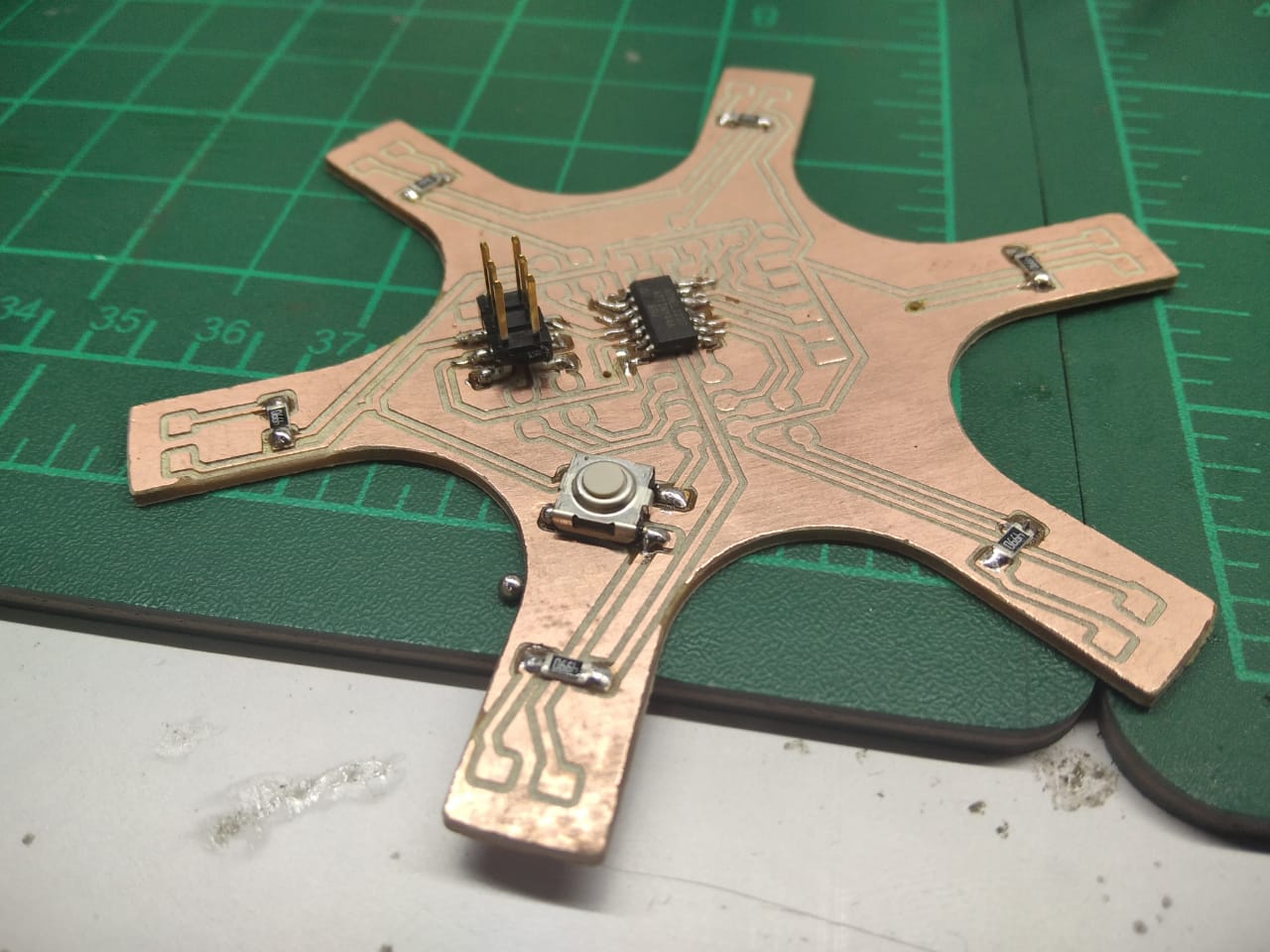
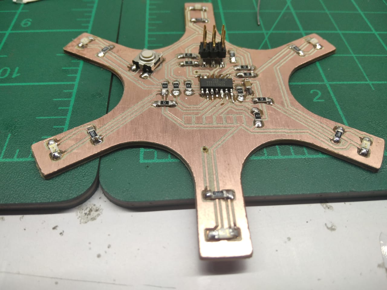
Soldering and Coding
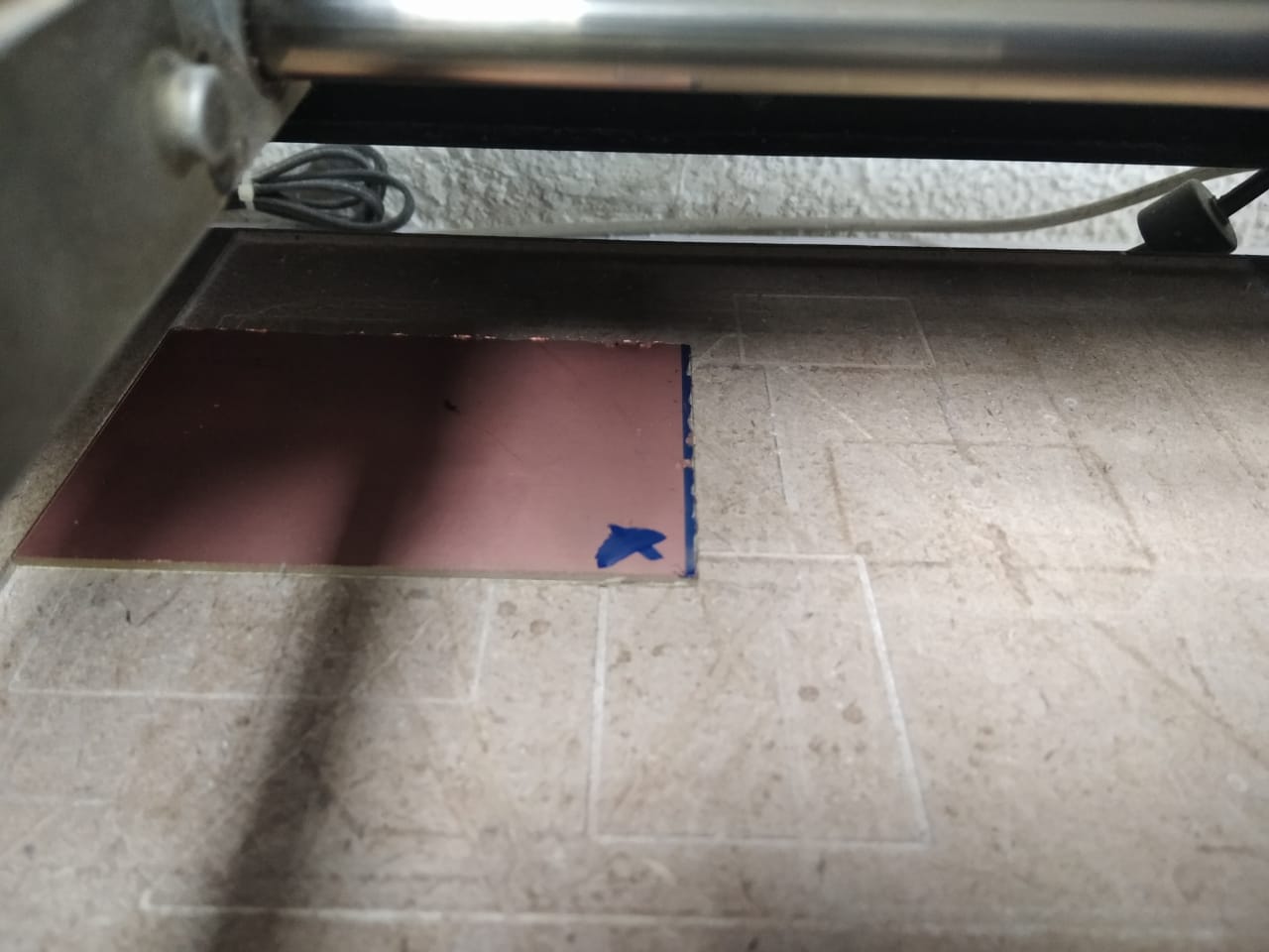
after we Designed out PCB we Fabricate it
and then solder the Component on it
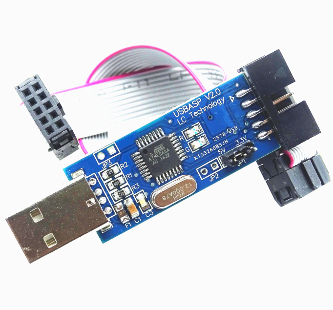
we will use USB ASP to Program the Circuit
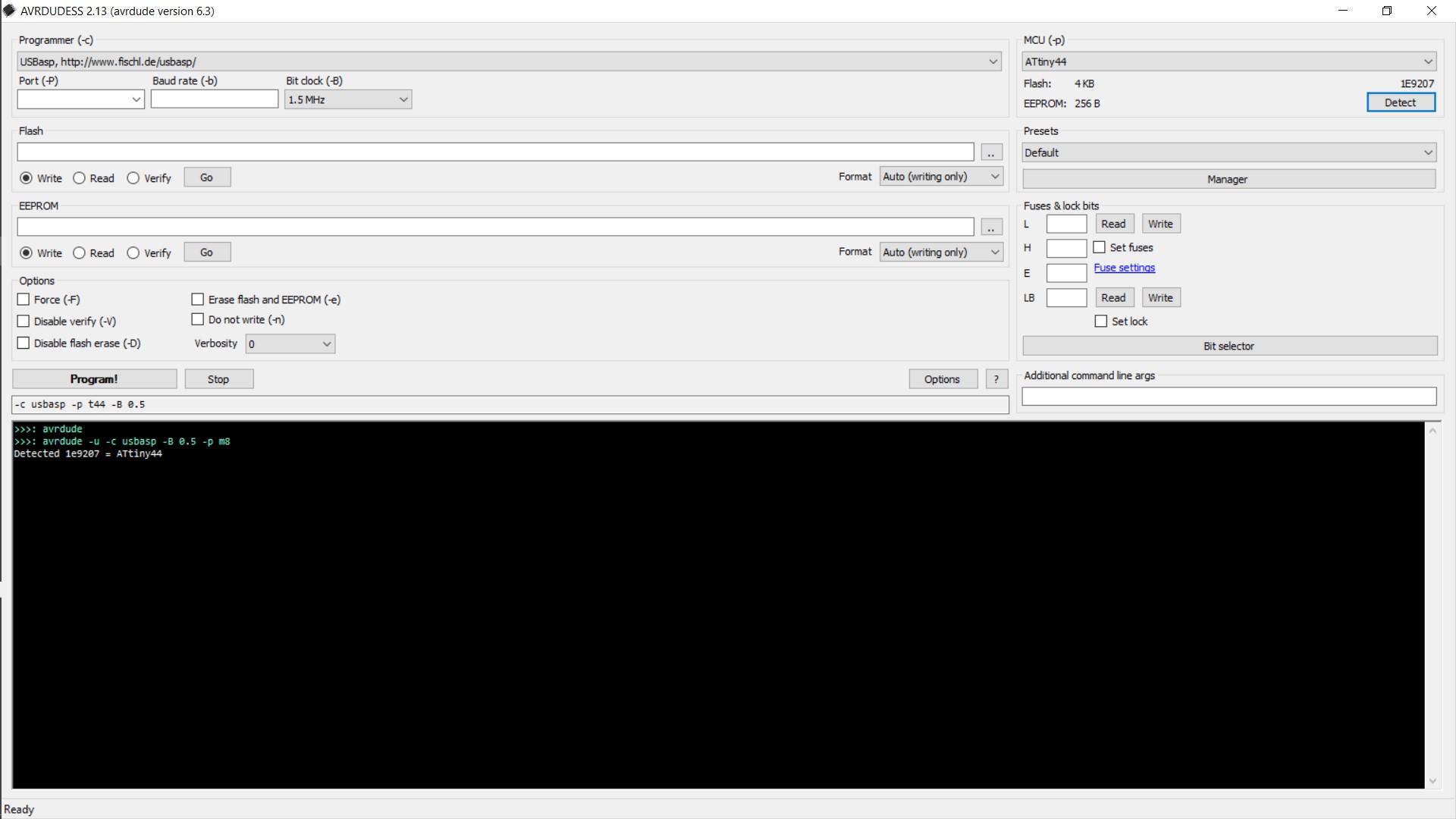
We will open AVR DUDES to see if our Circuit working or not (detect the ATTINY44)
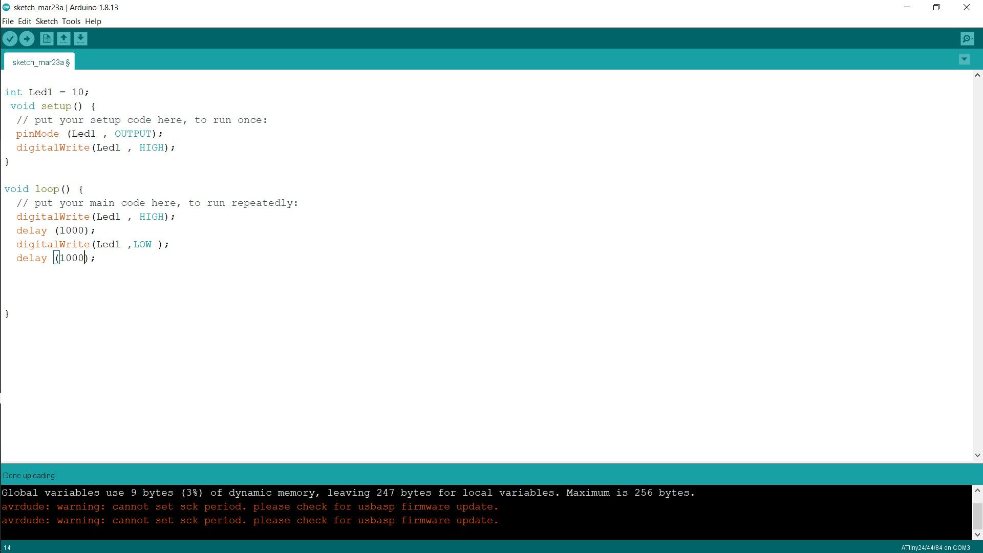
And then we will upload our code to the circuit by Arduino IDE
Then Let's see the Video
Downloads