9. Mechanical Design
Introduction
Almost all CNC machines have a single function per machine, despite that they may have the same design. In addition, the commercial solutions for a universal CNC machine are relatively expensive. In this project we will design and build an inexpensive CNC machine that could have many different attachments, all while controlled through a simple interface of G-code. The machine can perform milling and laser engraving operations. We wanted to build this CNC machine as a proof of concept while at the same time create something we could upgrade in the future.
Group Assignment
See complete machine Here.
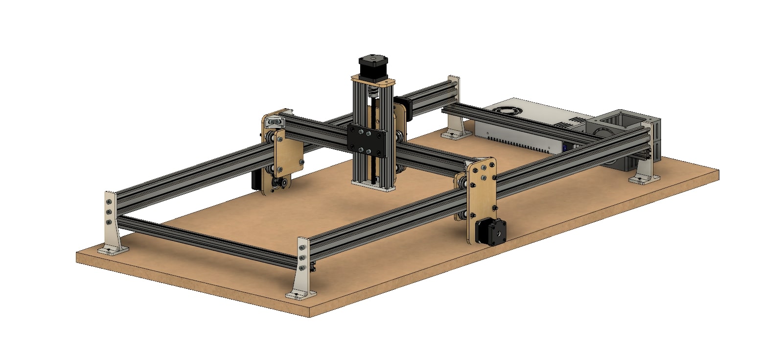
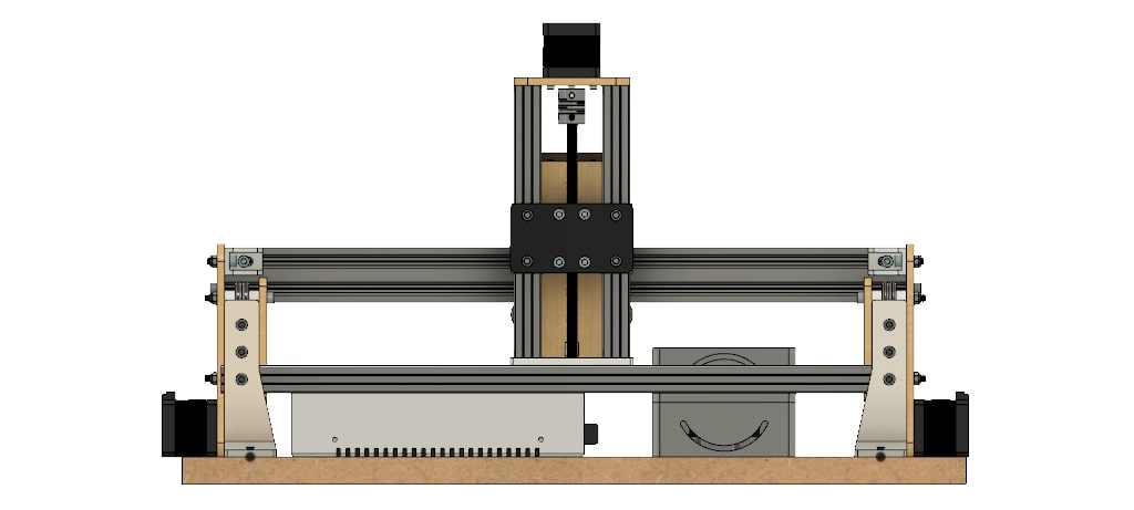
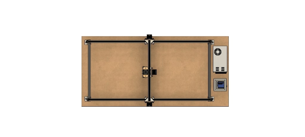
Design
We used Fusion 360 to create the design. The area of travel for the cutting tool is 320 mm in the X, 830 mm in the Y and 120 mm in the Z, but this could be increased if longer aluminum extrusions were used. The work piece itself is fixed on the waste board below the machine. The gantry moves along the Y-axis via belt drive with motors on either side of the frame. The X-axis moves perpendicular to the Y-axis along the gantry, also via belt drive. Attached to the X-axis is the Z-axis, which moves up and down via screw drive. The overall design is similar to the X-Carve mixed with the Open Builds Acro laser cutting system. Again, the goal of the machine is to allow it to be upgraded later on. This means the extrusions can be scaled up or down to fit your needs and budget. We have also designed the Z-axis to have a basic attachment scheme, meaning multiple tools can be attached so long as an adapter is designed with matching mounting holes. For my purpose, we’ve created an attachment for the Dremel and 2.5W laser. You could also design an adapter for a pen or even a 3D printer head to name a few options.
Parts
My role was designing the motor mounts and fixations on the guides .
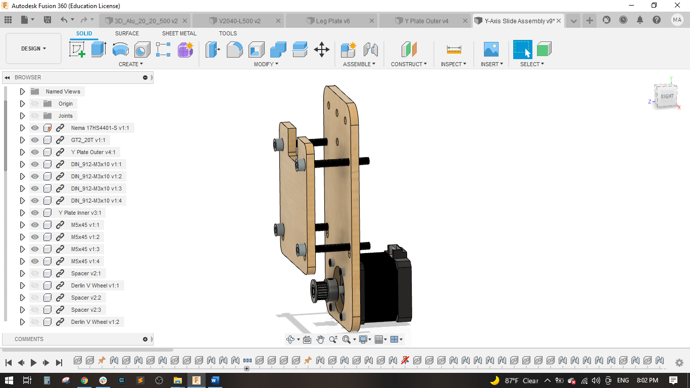
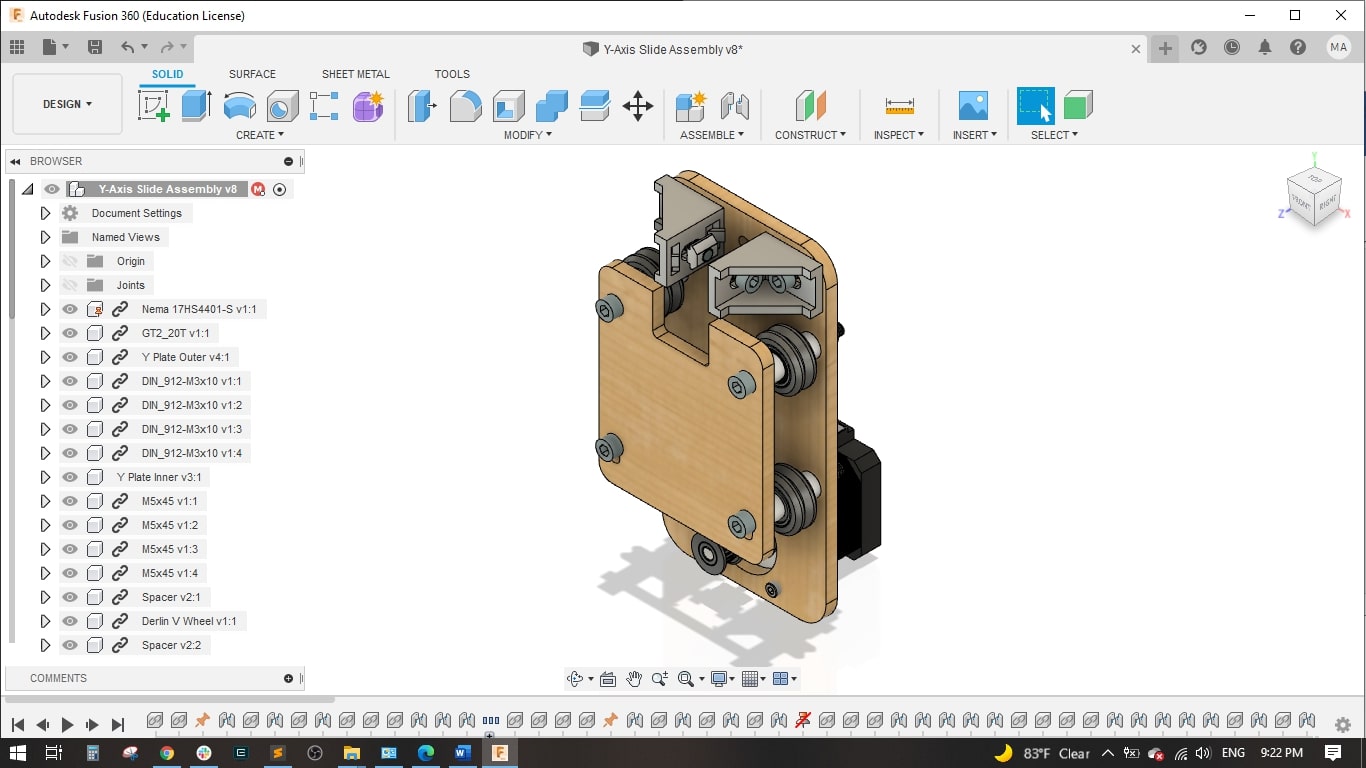
Y axis
I downloaded a NEMA17 Stepper Motor from GrabCAD and imported in into Fusion 360.
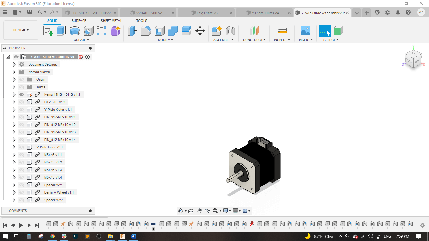
I designed an outer plate for this axis to be attached with the motor.
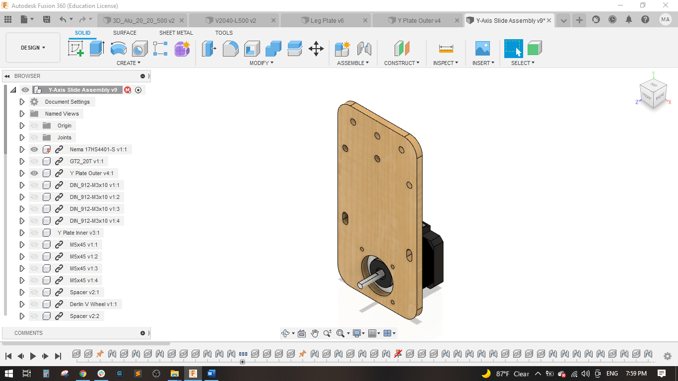
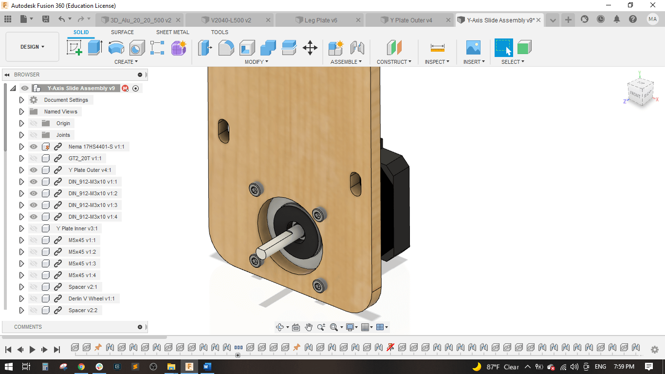
Used (4) M3*10 mm bolts to fix the motor with the plate.
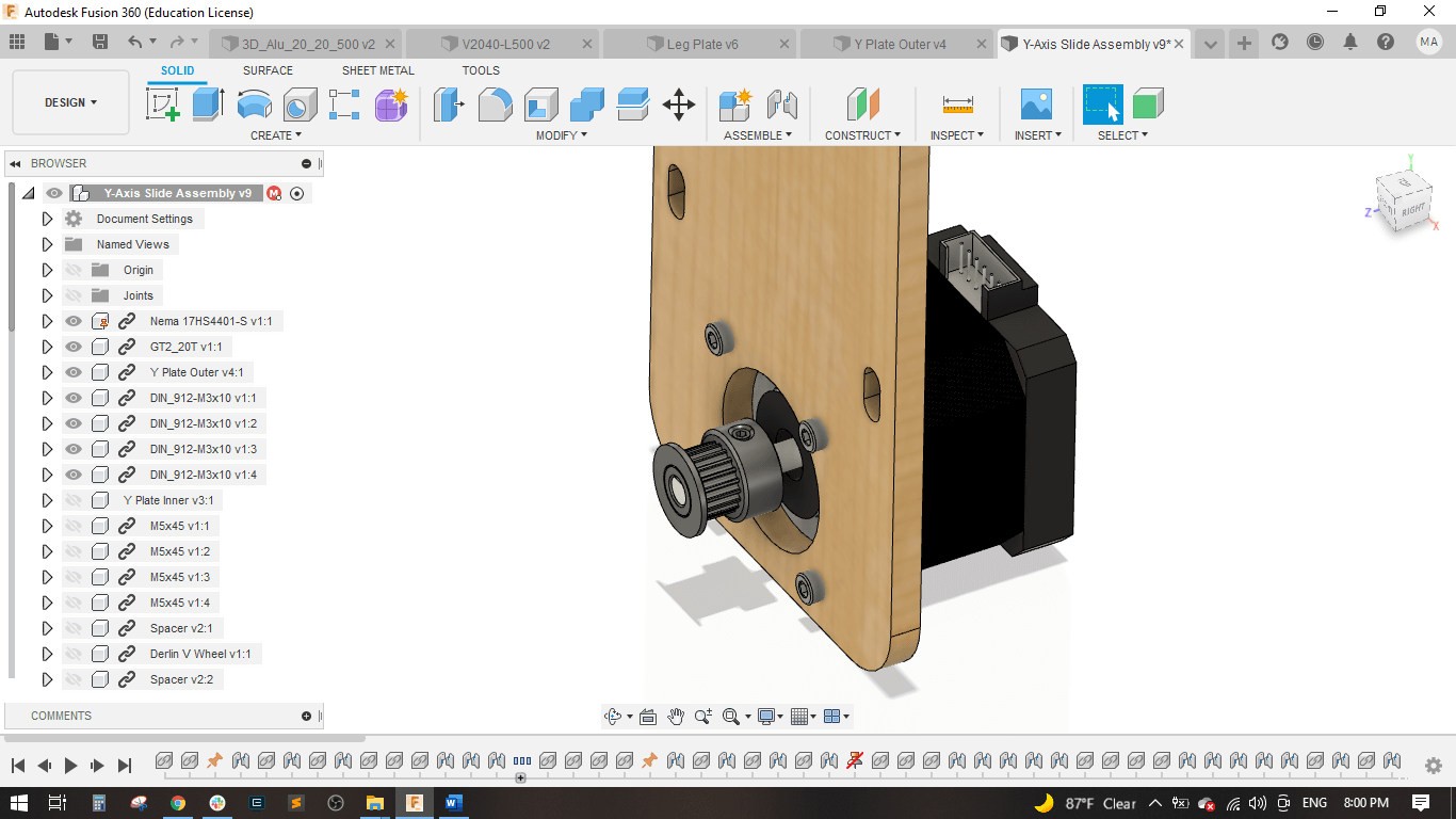
Attached a pulley of 5 mm inner diameter to the motor.
Designed an inner plate with identical holes and slots.
Attached (4) M5*45 mm bolts to fix the 2 plates together.
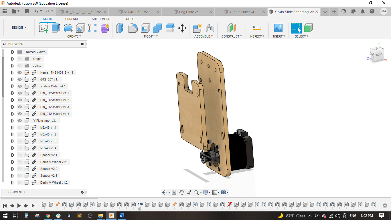
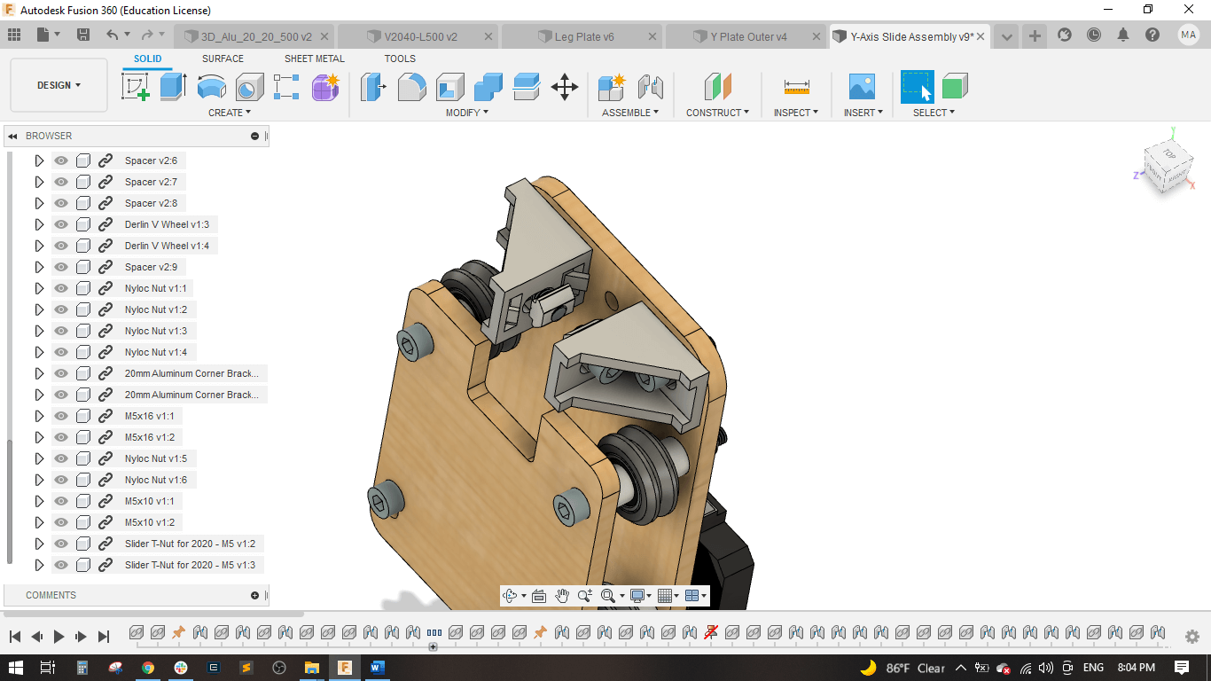
Added the V-wheels and spacers on the bolts between the two plates.
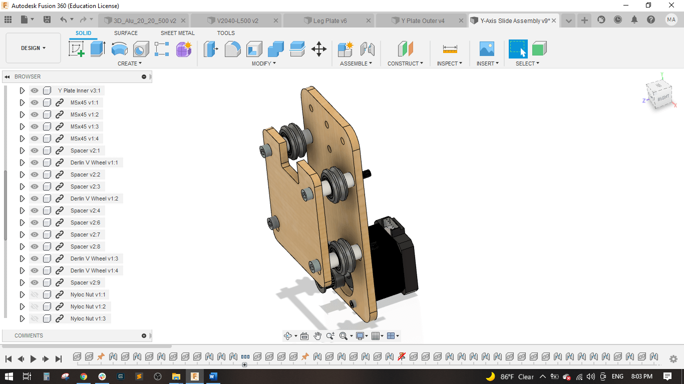
Locked the bolts with M5 lock nuts.
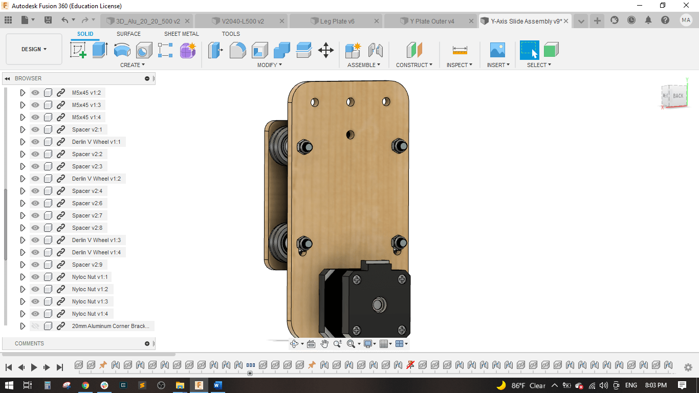
Attached (2) L-brackets to the outer plate to be fixed with the Aluminum profile.
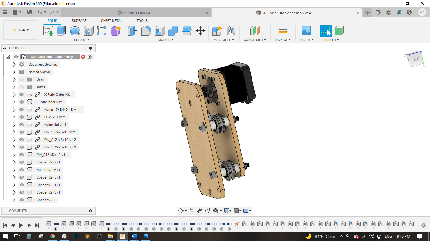
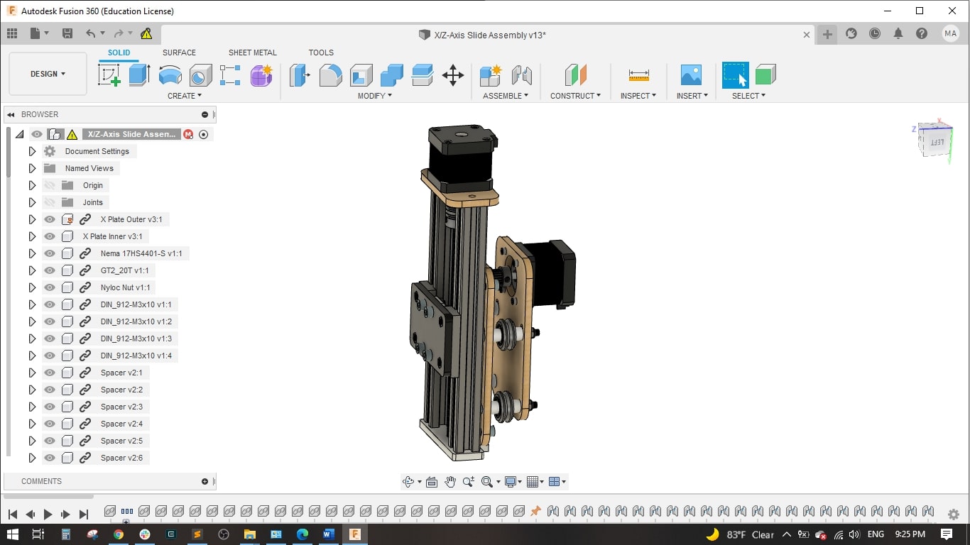
XZ axis
I started with the NEMA 17 stepper motor and attached the X plate outer with (4) M3*10 mm bolts to fix the motor.
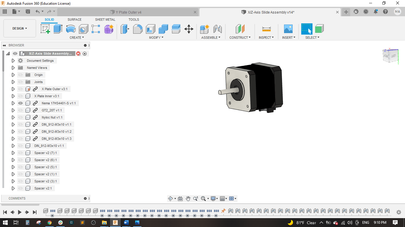
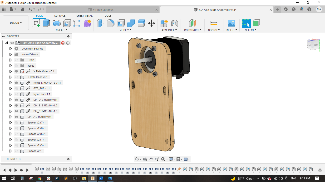
Attached the pulley to the motor shaft.
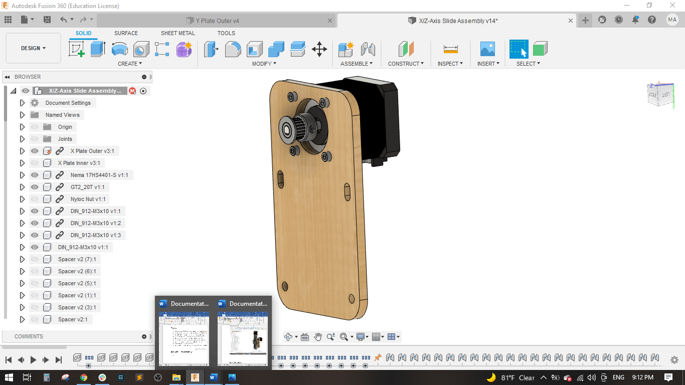
Added the inner plate with (4) M5*45 mm bolts.
Then added the spacer and the v-wheels.
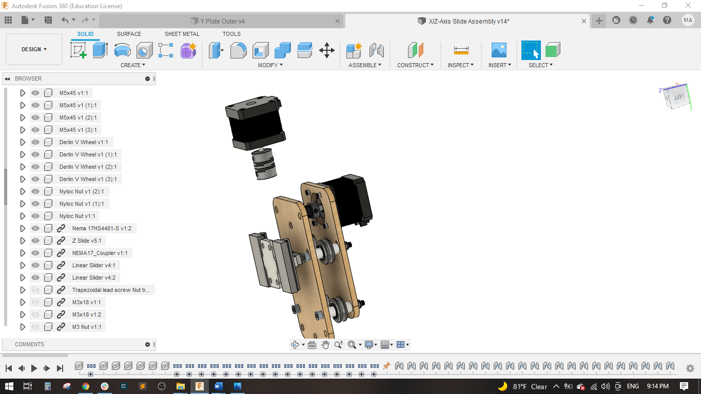
Added another NEMA 17 motor for the Z movement.
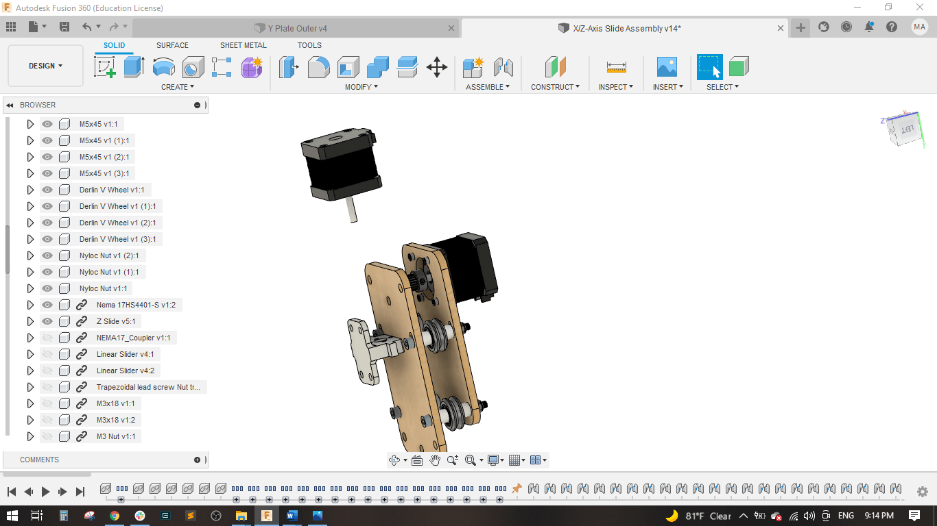
Attached a coupler 5-8 mm to the motor and designed sliders for the Z.
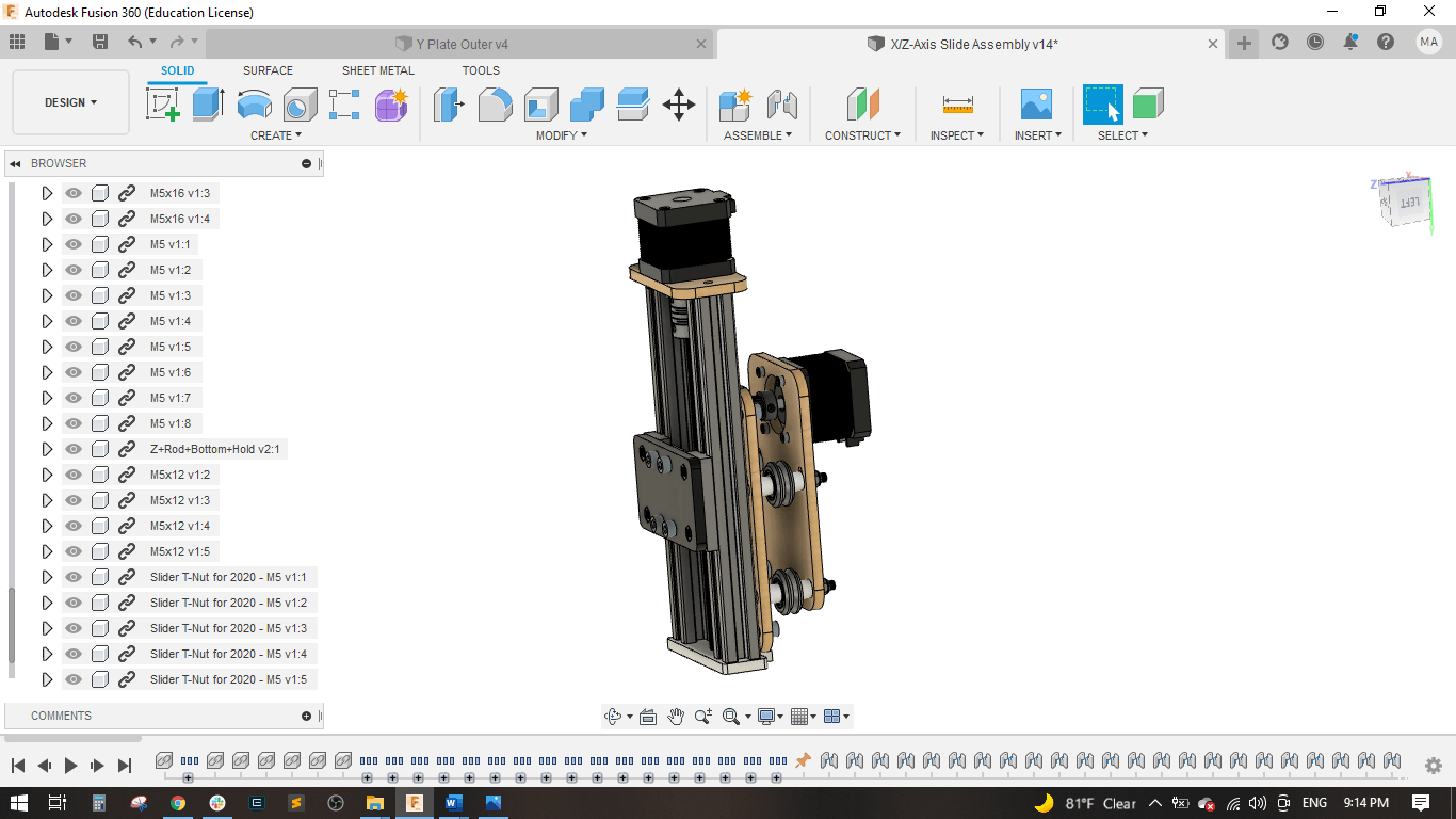
Added the 2020 Al profiles and the bottom Z plate.
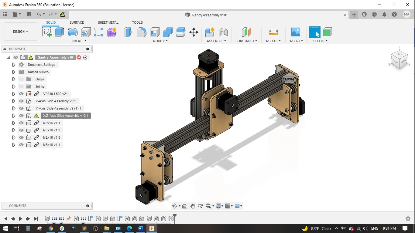
Gantry
Imported the X/Z assembly and two of the y-assembly.
Connected the two y-axes with a 2040 aluminum profile and then attach the X/Z assembly.
Now the gantry is ready.
Final Assembly
Attach (4) Leg Plates to the Waste board using (2) #6 x 1/2” Screws for each leg. Make sure they’re all squared and perpendicular to the edges.
Slide the 1050 mm Belt into the 2040 x 1000 mm so it lays in the extrusion slot. Slide in (1) M5 x 10 mm bolt with T-Slot Nut and tighten about 4 mm away from the end. One end of the belt is now fixed. Repeat for the second extrusion.
Slide the Gantry Assembly onto the extrusion and loop the belt so it goes under the wheels but around the belt pulley. Adjust the wheels so the extrusion moves freely but doesn’t wiggle too much. The belt should be aligned in the middle of the belt pulley.
Slide in (1) M5 x 10 mm bolt with T-Slot Nut into both extrusions and tighten about 4 mm away from the other end. Adjust as necessary so the belt is properly tensioned and the motor moves as the gantry is pushed back and forth.
Slide the assembly from Step 4 into place between the legs on the waste board. Use (2) M5 x 16 mm bolt on each leg to attach the leg to the extrusions. Place (1) M5 x 13 mm bolt and T-Slot Nut through the bottom leg holes. Do not fully tighten.
Slide (2) 2020 x 500 mm Extrusions onto the bottom T-Slot Nuts and tighten once in place.
Make sure the slides move freely and engage the belts. Check to make sure the frame is square and tighten all bolts.
Machine
Here is machine working