14. Interface and application programming
Group Assignment
It’s documented Here
Where we tested Processing 3 and App inventor .
Processing 3
Processing 3 was about writing code to describe or setup the user interface and assign functions .
Having 2 windows , one for writing the code and the second displys interface when the code is run .
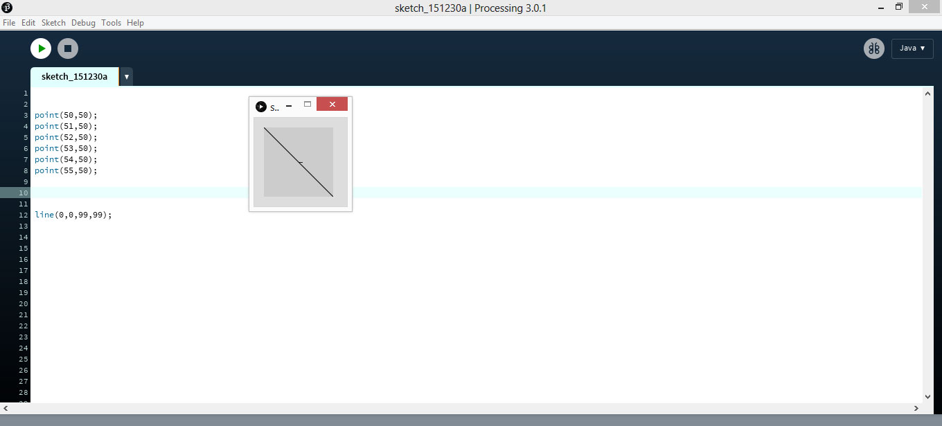
It’s a flexible software sketchbook and a language for learning how to code within the context of the visual arts.
It’s a free graphical library and integrated development environment built for the electronic arts, new media art, and visual design communities with the purpose of teaching non-programmers the fundamentals of computer programming in a visual context. uses the Java language, with additional simplifications such as additional classes and aliased mathematical functions and operations. It also provides a graphical user interface for simplifying the compilation and execution stage.
It’s a really useful language for real world applications (in its own domain of course). Processing is definitely useful for many purposes.
App Inventor
App Inventor lets you develop applications for Android phones .
It uses a graphic interface and coding in App Inventor isn’t necessary. It has a drag-and-drop interface. Very similar to Scratch
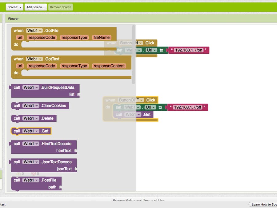
With all functions on the left
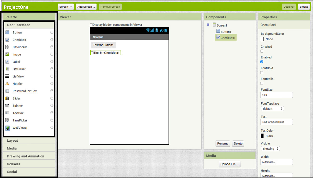
Once you choose one it opens all bricks for this function for you to start building your code
Conclusion
Processing 3 is suitable for most OS , huge capabilities and many books and tutorials are available . Yet it’s a programming language , requiring some syntax knowledge .
App Inventor is visual with puzzle like peices , easy and allow access to almost all phone functions and also using database and other apps on phone Yet it has some limitations such as user interface which has glitches while handling multiple screens and as Web access which is only allowed to APIs following a particular protocol .
What I will do
I decided to use processing 3 .. why ? It’s Open Source and free .
And I haven’t used it before . Unlike App Inventor , We had a few tries together .
My plan is to use to interface with a board I designed to introduce my younger brother to programming so I wanted it to be fun for him.
So the board will have 6 leds , and on the screen we will see 6 boxes and a button , corresponding to the leds .
Simply , choosing boxes to light when I press the button .
I started with this Tutorial , It was very helpful.
Board
Concept
To control the 6 leds , I am using the Charlieplexing technique . It’s a technique for driving a multiplexed display in which relatively few I/O pins on a microcontroller are used.
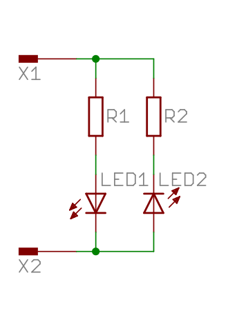
Charlieplexing in its simplest form works by using a diode matrix of pairs of LEDs connected in opposite directions.
For example , driving 2 leds :
By applying a positive voltage to pin X1 and grounding pin X2, LED1 will light. Since current cannot flow through LEDs in reverse direction at this low voltage, LED2 will remain unlit. If the voltages on pin X1 and pin X2 are reversed, LED2 will light and LED1 will be unlit.
As for driving 6 leds using 3 pins :
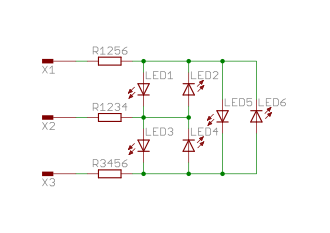
In order for this circuit to act like the previous one, one of the pins must be disconnected before applying charge to the remaining two. If, for example, LED5 was intended to be lit, X1 must be charged and X3 must be grounded. However, if X2 is also charged, LED3 would illuminate as well. If X2 was instead grounded, LED1 would illuminate, meaning that LED5 cannot be lit by itself. This can be solved by utilizing the tri-state logic properties of microcontroller pins. Microcontroller pins generally have three states: “high” (5 V), “low” (0 V) and “input”. Input mode puts the pin into a high-impedance state, which, electrically speaking, “disconnects” that pin from the circuit, meaning little or no current will flow through it. This allows the circuit to see any number of pins connected at any time, simply by changing the state of the pin. In order to drive the six-LED matrix above, the two pins corresponding to the LED to be lit are connected to 5 V (I/O pin “high” = binary number 1) and 0 V (I/O pin “low” = binary 0), while the third pin is set in its input state.
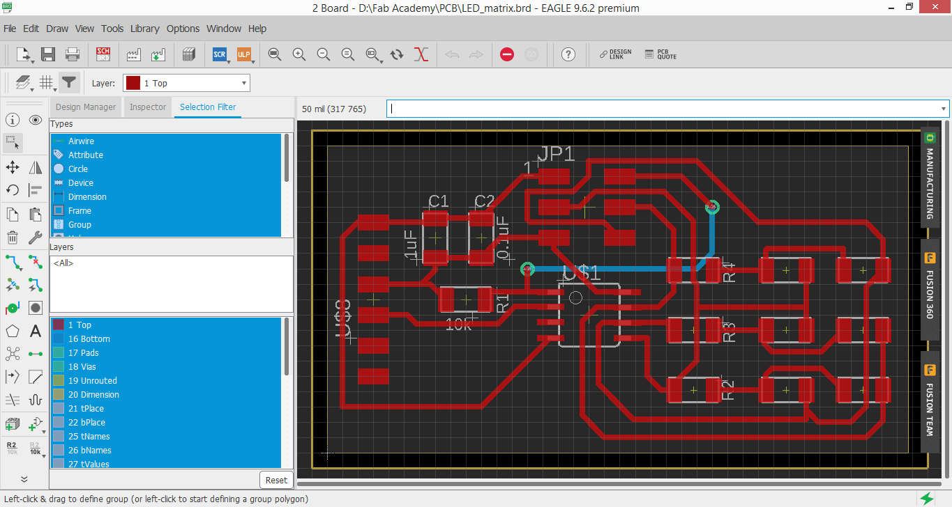
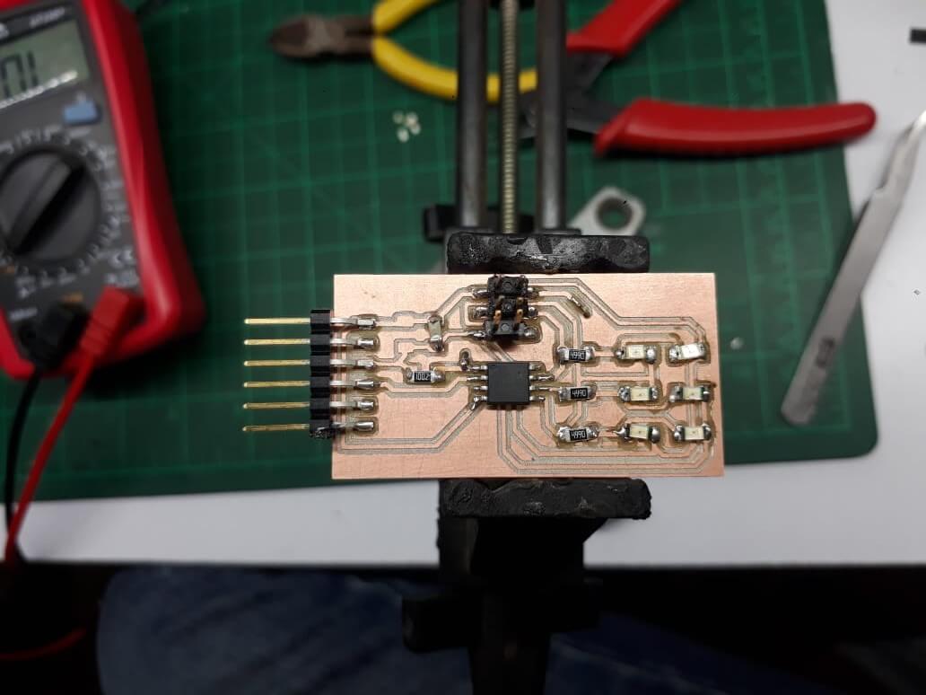
Design
Design on Eagle
Adding 6 Leds connected as a grid , Attiny45 , resistors and capacitors . FTDI and ISP
One trace failed completly to find a place for it on the Top , so I drew it on the buttom layer and it will be connected by a jumper .
From Eagle I export Gerber files .
Through Gerber viewer I get PDF of each toolpath : traces , drills and outline .
Gimp to Edit colors and fix image mode .
And export the png files .
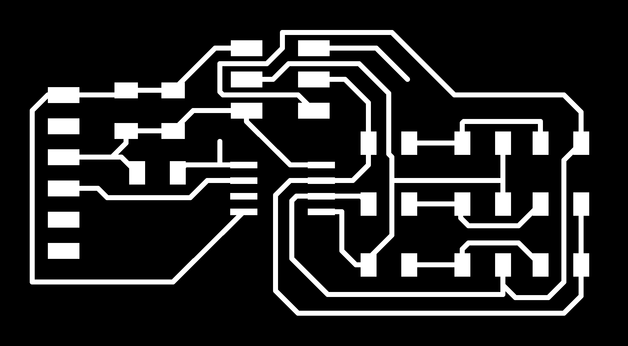
Through Fab modules , we import the png and edit milling settings,
These settings are on Week 4 of Electronics production .
Fabrication
And Off to milling on Modella MDX 20
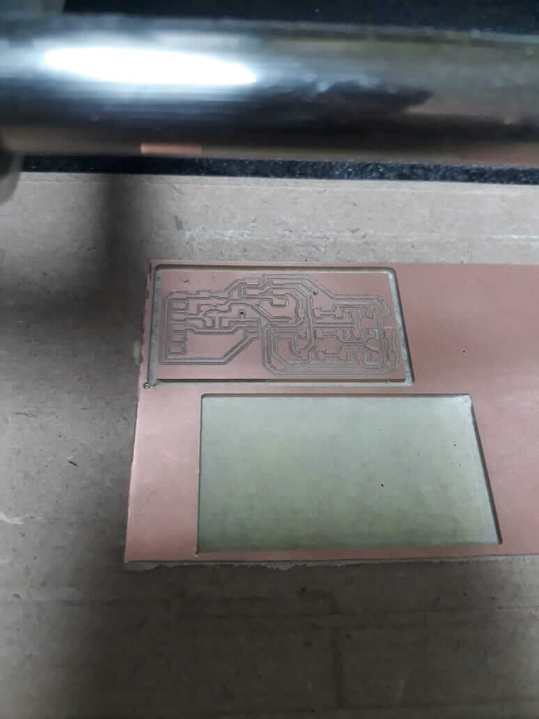
Then Soldering , As I started with attiny45 , in center and low height .
followed by leds , resistors and capacitors . Finished with FTDI and ISP .
Find design file Here
Coding
Board Code
Here is the arduino code ..
It’s a code for Leds array with many interesting fuctions
Like “led_cycle_CCW” which will flash leds as if they were spinning counter clockwise.
Right now , I’m just using “Flash_Pattern” function , which gets data from Processing 3 and flashes Leds corresponding to them .
//
//
// hello.array.44.c
//
// Charlieplex LED array hello-world
//
// Neil Gershenfeld
// 11/13/10
//
// (c) Massachusetts Institute of Technology 2010
// This work may be reproduced, modified, distributed,
// performed, and displayed for any purpose. Copyright is
// retained and must be preserved. The work is provided
// as is; no warranty is provided, and users accept all
// liability.
//

#include <avr/io.h>
#include <util/delay.h>

#define output(directions,pin) (directions |= pin) // set port direction for output
#define input(directions,pin) (directions &= (~pin)) // set port direction for input
#define set(port,pin) (port |= pin) // set port pin
#define clear(port,pin) (port &= (~pin)) // clear port pin
#define pin_test(pins,pin) (pins & pin) // test for port pin
#define bit_test(byte,bit) (byte & (1 << bit)) // test for bit set

#define bit_delay_time 102 // bit delay for 9600 with overhead
#define bit_delay() _delay_us(bit_delay_time) // RS232 bit delay
#define half_bit_delay() _delay_us(bit_delay_time/2) // RS232 half bit delay


#define led_delay() _delay_ms(1) // LED delay

#define flash_delay 1

#define led_port PORTB
#define led_direction DDRB

#define C (1 << PB0) // row 1
#define B (1 << PB1) // row 2
#define A (1 << PB2) // row 3

#define serial_port PORTB
#define serial_direction DDRB
#define serial_pins PINB
#define serial_pin_in (1 << PB3)

void get_char(volatile unsigned char *pins, unsigned char pin, char *rxbyte) {
   //
   // read character into rxbyte on pins pin
   //    assumes line driver (inverts bits)
   //
   *rxbyte = 0;
   while (pin_test(*pins,pin))
      //
      // wait for start bit
      //
      ;
   //
   // delay to middle of first data bit
   //
   half_bit_delay();
   bit_delay();
   //
   // unrolled loop to read data bits
   //
   if pin_test(*pins,pin)
      *rxbyte |= (1 << 0);
   else
      *rxbyte |= (0 << 0);
   bit_delay();
   if pin_test(*pins,pin)
      *rxbyte |= (1 << 1);
   else
      *rxbyte |= (0 << 1);
   bit_delay();
   if pin_test(*pins,pin)
      *rxbyte |= (1 << 2);
   else
      *rxbyte |= (0 << 2);
   bit_delay();
   if pin_test(*pins,pin)
      *rxbyte |= (1 << 3);
   else
      *rxbyte |= (0 << 3);
   bit_delay();
   if pin_test(*pins,pin)
      *rxbyte |= (1 << 4);
   else
      *rxbyte |= (0 << 4);
   bit_delay();
   if pin_test(*pins,pin)
      *rxbyte |= (1 << 5);
   else
      *rxbyte |= (0 << 5);
   bit_delay();
   if pin_test(*pins,pin)
      *rxbyte |= (1 << 6);
   else
      *rxbyte |= (0 << 6);
   bit_delay();
   if pin_test(*pins,pin)
      *rxbyte |= (1 << 7);
   else
      *rxbyte |= (0 << 7);
   //
   // wait for stop bit
   //
   bit_delay();
   half_bit_delay();
   }


void flash(uint8_t from, uint8_t to, uint8_t delay) {
   //
   // source from, sink to, flash
   //
   static uint8_t i;
   set(led_port,from);
   clear(led_port,to);
   output(led_direction,from);
   output(led_direction,to);
   for (i = 0; i < delay; ++i)
       led_delay();
   input(led_direction,from);
   input(led_direction,to);
   }

void led_cycle_CCW(uint8_t number, uint8_t delay) {
   //
   // cycle through LEDs
   //
   uint8_t i;
   for (i = 0; i < number; ++i) {
      flash(A,B,delay);
      flash(A,C,delay);
      flash(B,A,delay);
      flash(B,C,delay);
      flash(C,A,delay);
      flash(C,B,delay);
      }
   }
void led_cycle_CW(uint8_t number, uint8_t delay) {
   //
   // cycle through LEDs
   //
   uint8_t i;
   for (i = 0; i < number; ++i) {
      flash(C,B,delay);
      flash(B,C,delay);
      flash(B,A,delay);
      flash(C,A,delay);
      flash(A,C,delay);
      flash(A,B,delay);
      }
   }

void flash_all(uint8_t number)
{
   for (int i = 0; i < number; ++i)
   {
      flash(A, B, flash_delay);
      flash(A, C, flash_delay);
      flash(B, A, flash_delay);
      flash(B, C, flash_delay);
      flash(C, A, flash_delay);
      flash(C, B, flash_delay);
   }
}
void dance(void)
{
   led_cycle_CCW(10, 50);
   flash_all(100);
   led_cycle_CW(10, 50);
   flash_all(100);
}

void flash_pattern(uint8_t pattern, uint8_t number)
{
   for (int i = 0; i < number; ++i)
   {
      if((pattern >> 1) & (1))
         flash(A, B, flash_delay);
      if((pattern >> 2) & (1))
         flash(A, C, flash_delay);

      if((pattern >> 3) & (1))
         flash(B, A, flash_delay);
      if((pattern >> 4) & (1))
         flash(B, C, flash_delay);

      if((pattern >> 5) & (1))
         flash(C, A, flash_delay);
      if((pattern >> 6) & (1))
         flash(C, B, flash_delay);
   }
}

static char chr;

void setup()
{
   //
   // set clock divider to /1
   //
   CLKPR = (1 << CLKPCE);
   CLKPR = (0 << CLKPS3) | (0 << CLKPS2) | (0 << CLKPS1) | (0 << CLKPS0);

}

void loop()
{
    //allow processing 3 communication
      get_char(&serial_pins,serial_pin_in,&chr);
      flash_pattern(chr, 2000);
}
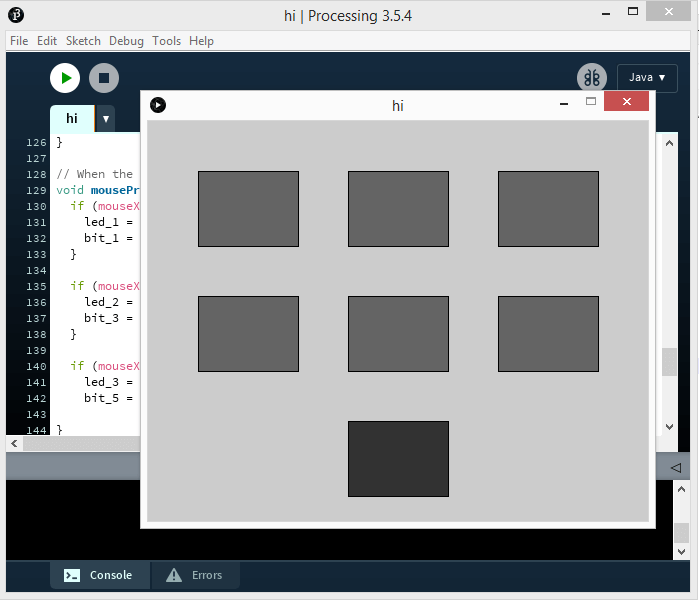
Processing 3 Code
Processing 3 Code was easy and amuzing , we’re actually drawing with lines .
Some commands specify dimensions of squares and some specify their color when On or Off .
I added comments on Code to highlight these .
Last few lines are about collecting data of what buttons are pushed On and when send Button is pushed , This data is sent to board .
First , Importing the serial communication library and defining some variables
import processing.serial.*;

Serial myserial;

int data = 0;

boolean led_1 = false;
boolean led_2 = false;
boolean led_3 = false;
boolean led_4 = false;
boolean led_5 = false;
boolean led_6 = false;

int bit_1 = 0;
int bit_2 = 0;
int bit_3 = 0;
int bit_4 = 0;
int bit_5 = 0;
int bit_6 = 0;
Then define the buttons , positions of each one’s top left corner . We have 7 buttons , 6 corresponding to leds and 1 to send data .
int offsetx = 150;  // distance between buttons horizontally
int offsety = 125;  // distance between buttons verticaly
int x1 = 50;
int y1 = 50;

int x2 = x1 + offsetx;
int y2 = y1;

int x3 = x2 + offsetx;
int y3 = y2;

int x4 = 50;
int y4 = y1 + offsety;

int x5 = x4 + offsetx;
int y5 = y4;

int x6 = x5 + offsetx;
int y6 = y5;

int x7 = x5;
int y7 = y6 + offsety;

int w = 100;   // Square width
int h = 75;    // Square height
in void setup , we initiate communication
void setup() {
  size(500, 400);

  String myPort = Serial.list()[1];

  myserial = new Serial(this, myPort, 9600);
}
Setting color of buttons when On and Off
// Colors of on and off buttons
void draw() {
  if (led_1)
  {
    fill(255);
    rect(x1,y1,w,h);
  }
  else
  {
    fill(100);
    rect(x1,y1,w,h);
  }

  if (led_2)
  {
    fill(255);
    rect(x4,y4,w,h);
  }
  else
  {
    fill(100);
    rect(x4,y4,w,h);
  }

    if (led_3)
  {
    fill(255);
    rect(x2,y2,w,h);
  }
  else
  {
    fill(100);
    rect(x2,y2,w,h);
  }

  if (led_4)
  {
    fill(255);
    rect(x5,y5,w,h);
  }
  else
  {
    fill(100);
    rect(x5,y5,w,h);
  }

  if (led_5)
  {
    fill(255);
    rect(x3,y3,w,h);
  }
  else
  {
    fill(100);
    rect(x3,y3,w,h);
  }

  if (led_6)
  {
    fill(255);
    rect(x6,y6,w,h);
  }
  else
  {
    fill(100);
    rect(x6,y6,w,h);
  }

  fill(50);
  rect(x7, y7, w, h);

}
When the mouse is pressed, the state of the button is toggled.
void mousePressed() {
  if (mouseX > x1 && mouseX < x1+w && mouseY > y1 && mouseY < y1+h) {
    led_1 = !led_1;
    bit_1 = bit_1 ^ 1;
  }

  if (mouseX > x4 && mouseX < x4+w && mouseY > y4 && mouseY < y4+h) {
    led_2 = !led_2;
    bit_2 = bit_2 ^ 1;
  }

  if (mouseX > x2 && mouseX < x2+w && mouseY > y2 && mouseY < y2+h) {
    led_3 = !led_3;
    bit_3 = bit_3 ^ 1;

}

  if (mouseX > x5 && mouseX < x5+w && mouseY > y5 && mouseY < y5+h) {
    led_4 = !led_4;
    bit_4 = bit_4 ^ 1;

}

   if (mouseX > x3 && mouseX < x3+w && mouseY > y3 && mouseY < y3+h) {
    led_5 = !led_5;
    bit_5 = bit_5 ^ 1;

}

    if (mouseX > x6 && mouseX < x6+w && mouseY > y6 && mouseY < y6+h) {
    led_6 = !led_6;
    bit_6 = bit_6 ^ 1;

}

  if (mouseX > x7 && mouseX < x7+w && mouseY > y7 && mouseY < y7+h) {
    data = bit_6<<6 | bit_5<<5 | bit_4<<4 | bit_3<<3 | bit_2<<2 | bit_1<<1;
    myserial.write(data);
  }

}
Run the code and test
Turned out that some leds responded to wrong bottoms , so I had to switch their commanding lines and now it’s working properly !!
Action
My younger brother had fun switching leds on and off .