12. Molding and Casting
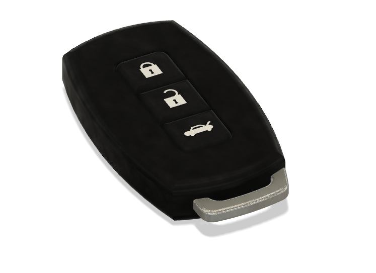
This week, I am making progress on my final project by creating a case to hold the components. The case is to resemble a key fob.

The reason why my mold and cast will resemble a key fob is because I was a simple tool that had a bottom which is easy to click and use and I feel that a key fob has a simple design for a bottom.
The goal was to make somethings like this video How to make 2 part mold to duplicate door remote control cover - Malaysia Clay Art except, I would have to design the key fob.
Molding
To help me along the journey of molding my key fob. I found several resources online:
- Fusion 360 Tutorial — Beginner To Advanced — How To Create a Mold— Part 1
- How to Make Molds in Fusion 360
- How to Create a Two-Part Mold in Fusion 360 - Learn Autodesk Fusion 360 in 30 Days: Day #21
- How to Create a One-Part Mold in Fusion 360 - Learn Autodesk Fusion 360 in 30 Days: Day #20
I started off in Fusion 360 designing a key fob look alike. But, before I design my own, I searched the internet for inspiration. I eventually found a key fob design on the AutoDesk gallery - Car Key Fob. That said, instead of designing a key fob from scratch, I decided to use the key fob design from Franklin Turza. After reading the Terms and Agreements, I realized that I can use and modify the Car Key Fob for noncommercial purpose. You can read more about the Legal Notices & Trademark.
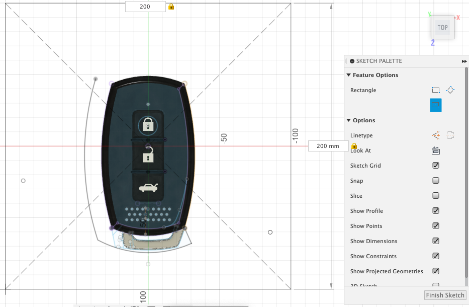
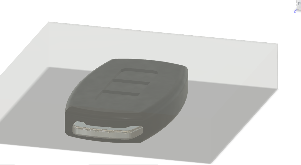
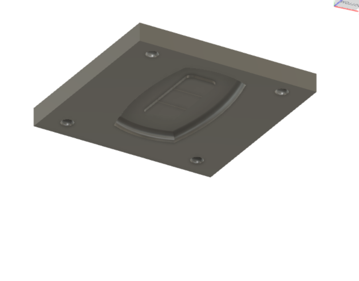
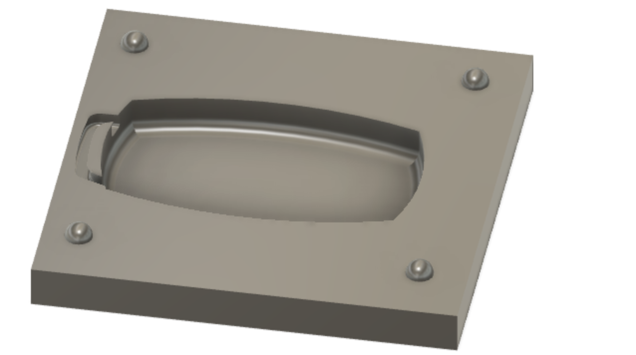
After downloading the Key Fob and importing it into Fusion 360,
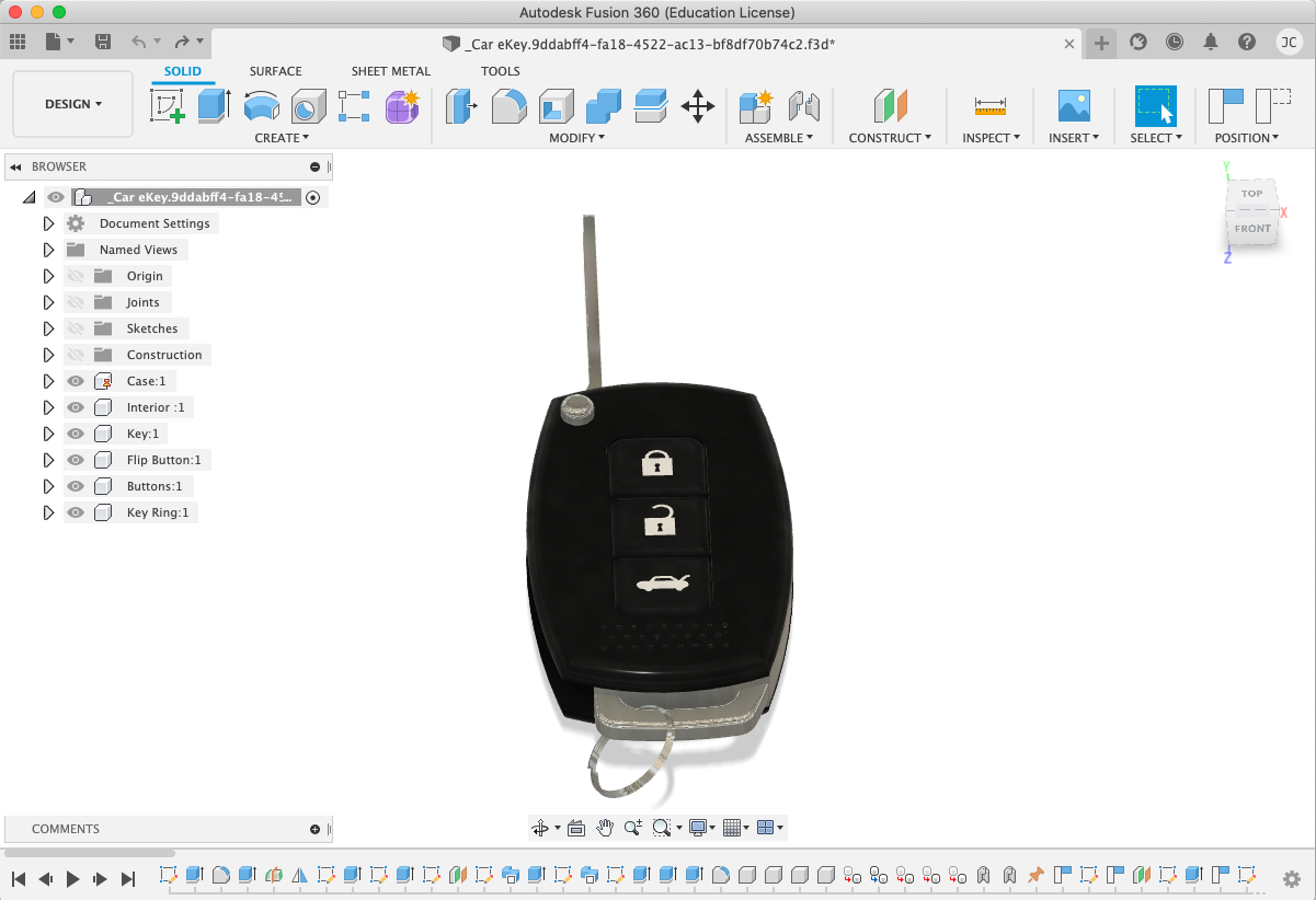
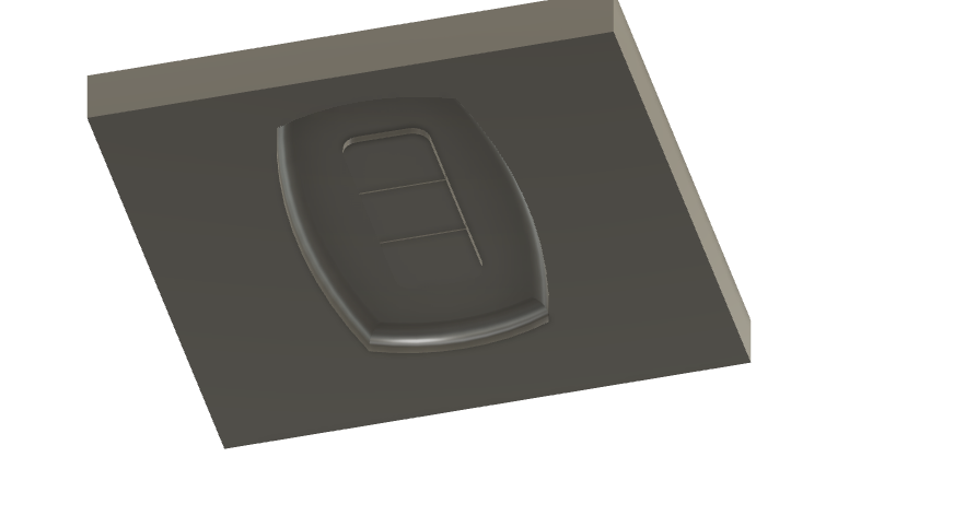
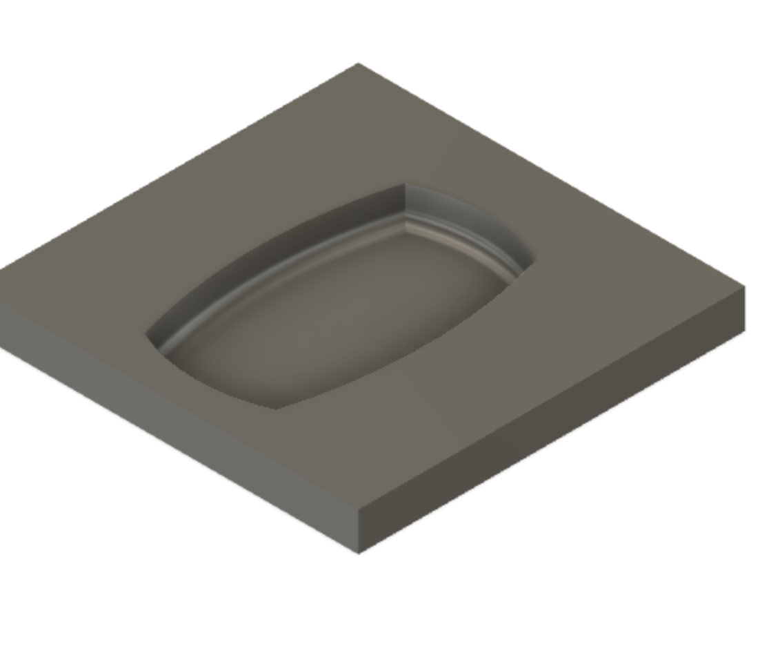
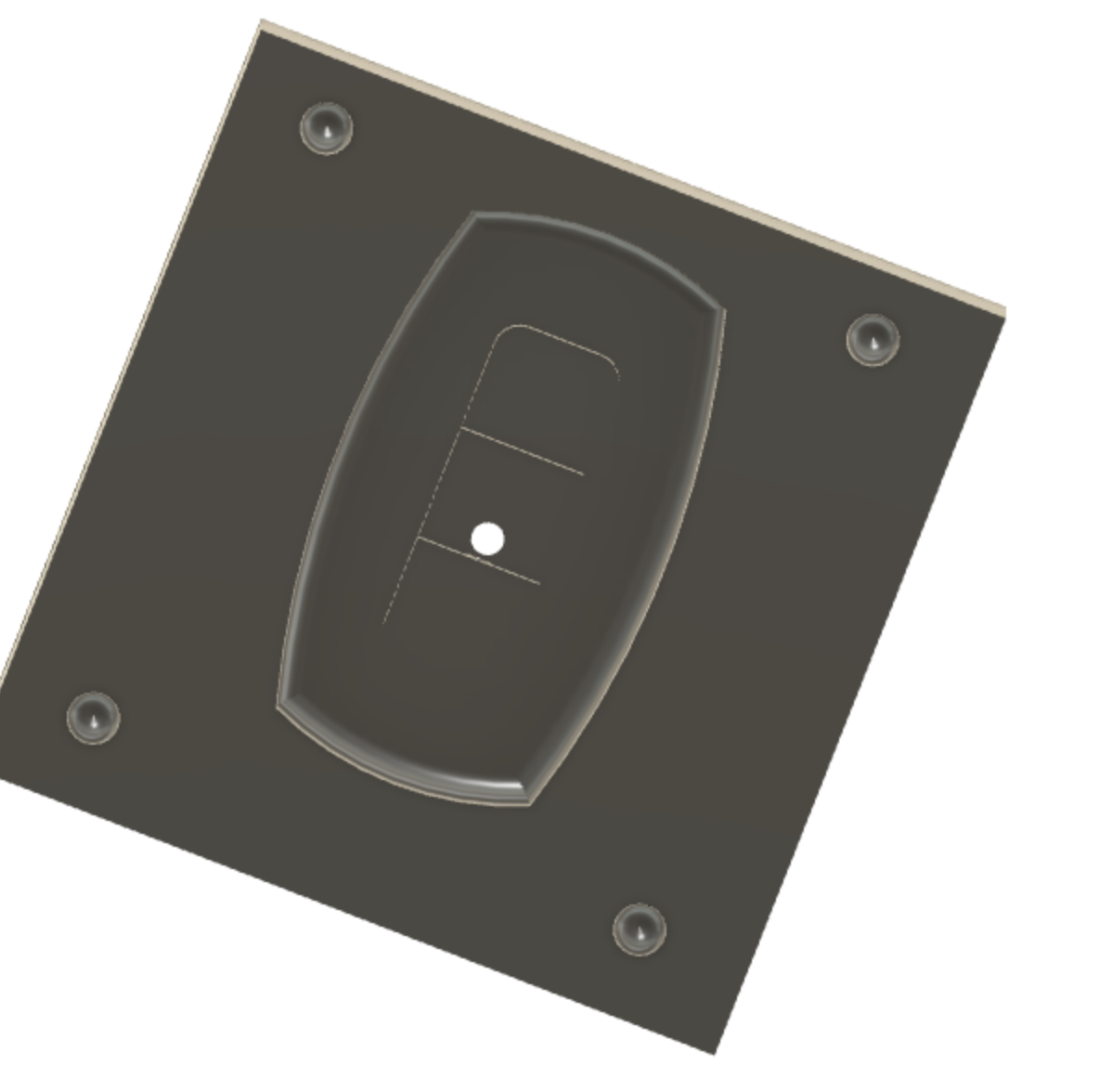
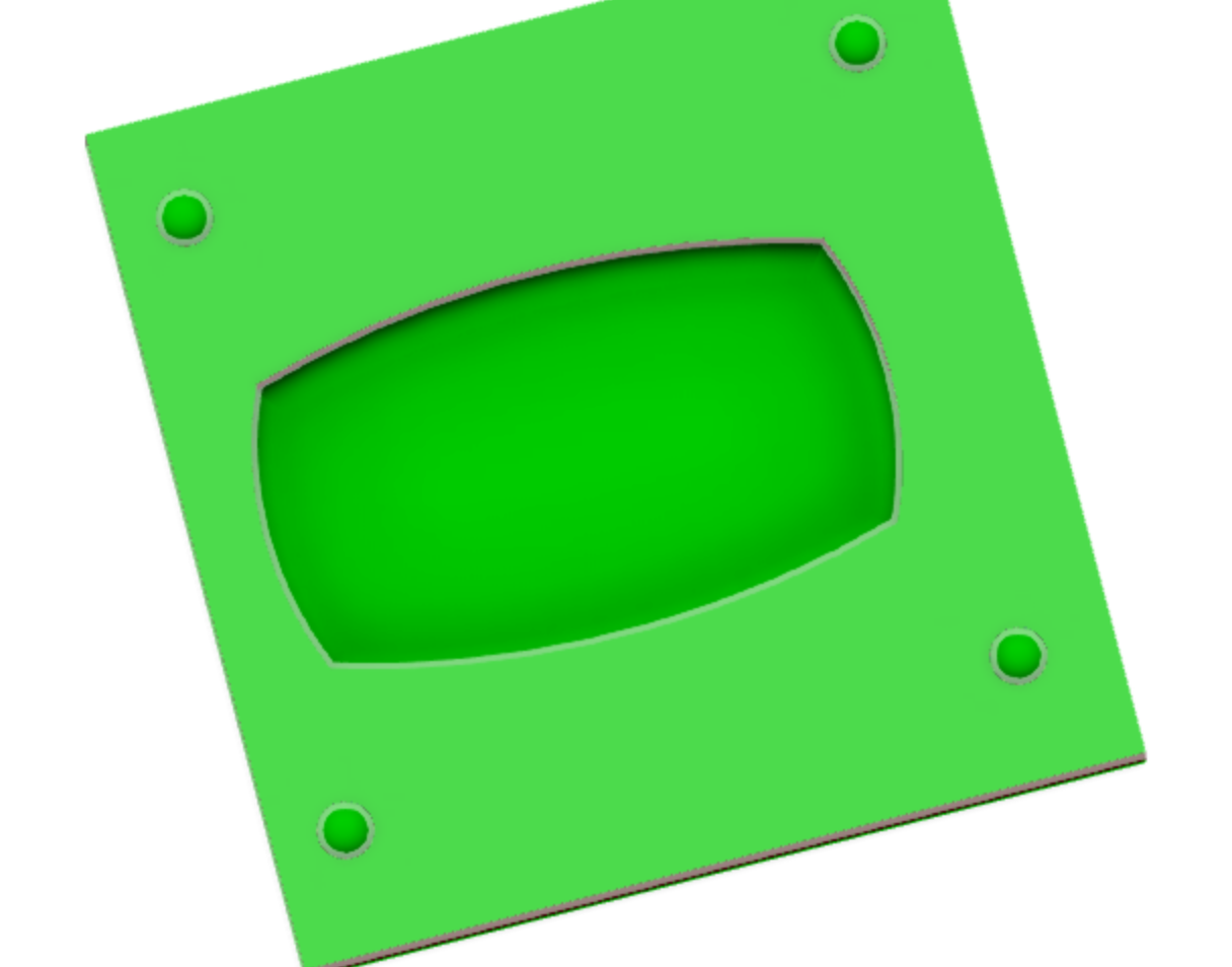
the next step was to edit it to fit my imagination. So, after a few minutes of editing, the result came to be:
Since this design will require a Two-Part mold, I watched the How to Create a Two-Part Mold in Fusion 360 - Learn Autodesk Fusion 360 in 30 Days: Day #21 video for guidance. Note: We create a two part mold when the two-dimensional object is too complex for a one-part mold.
The first I did was create a box that encompass the entire object.
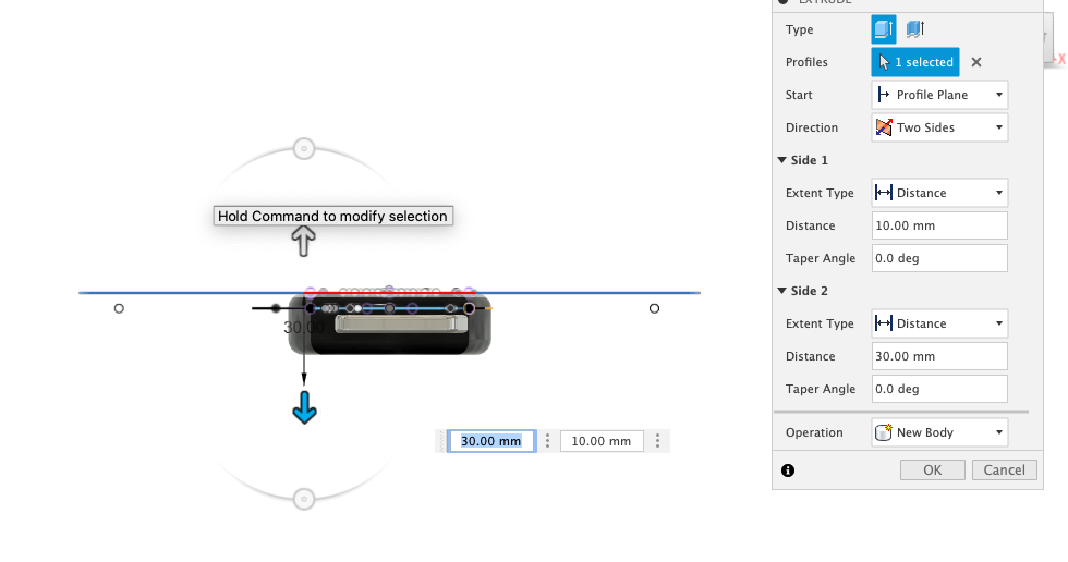
Now, I extruded the rectangle and the goal is that the extrusion covers the entire object. Note: Make sure you have New Body set as the current operation before pressing okay.
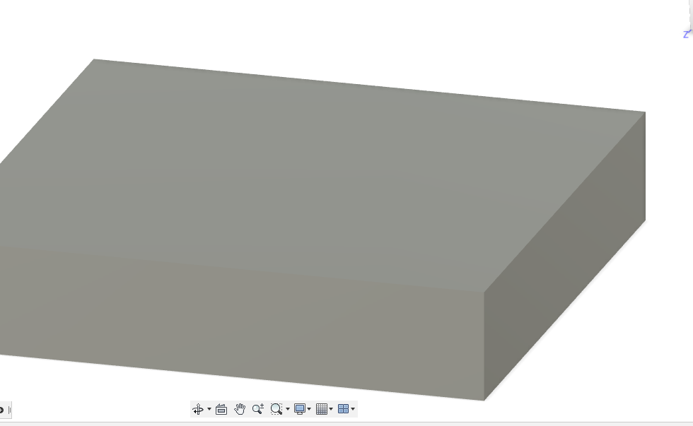
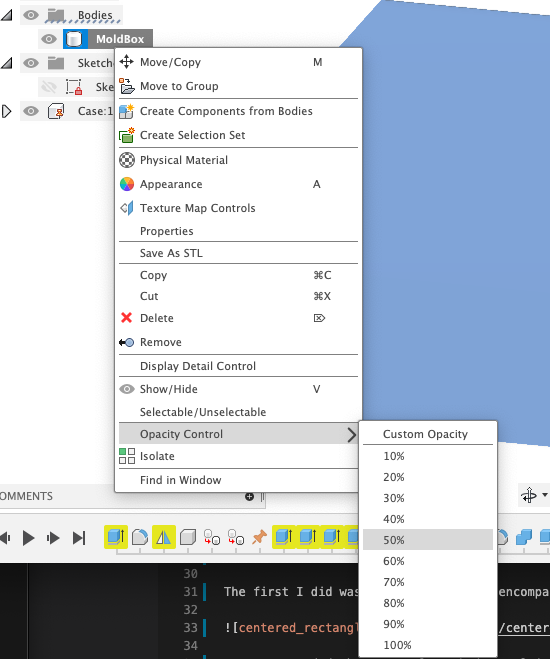
To see what’s going on, I changed the opacitt of the mold body.
The result:
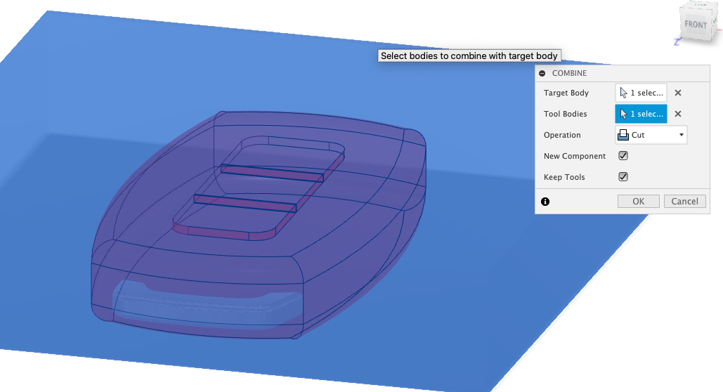
To subtract the shape from the box, I used the combine tool.
At this point, I was to cut the mold into two parts. But, before we split the body, I will need to add a construction plane to reference as the split feature. To do so, I selected Construct > Midplane and selected the top of the mold and then the bottom of the mold.
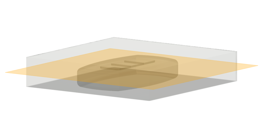
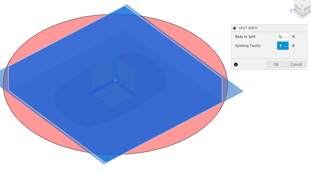
From there, I selected split body from the Modity drop down (Modify > Split-Body):
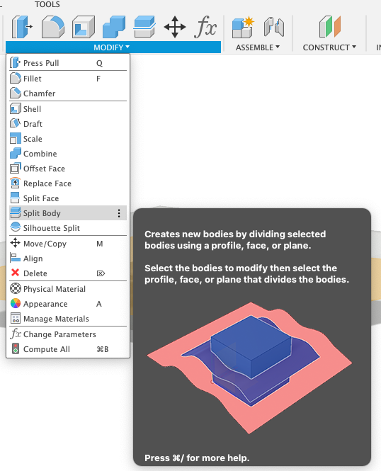
I selected the mold box as the body to split and the construction plane as the splitting tool.
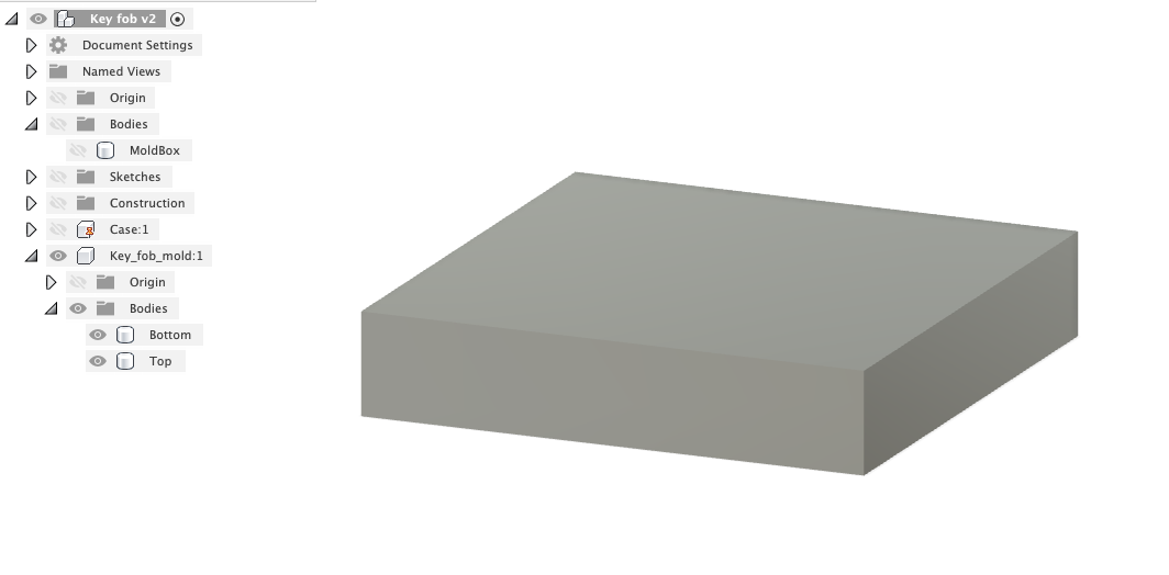
From there, to make visibility easier, I changed the opacity for the mold back to 100% and renamed the Bottom amd Top:
As a result, I am able to hide the top to see the bottom:
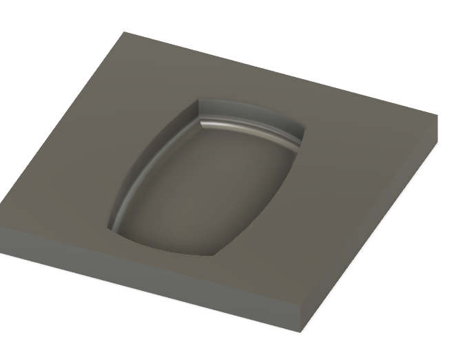
and hide the bottom to see the top:
Now, to do a few more things. I need to create some registration pins so the mold always lines up correctly when it’s placed together and I also need to create a hole that allows the resin to get into this inside cavity.
I start off by creating the registration pins. To start, I selected the Top body and hid it.
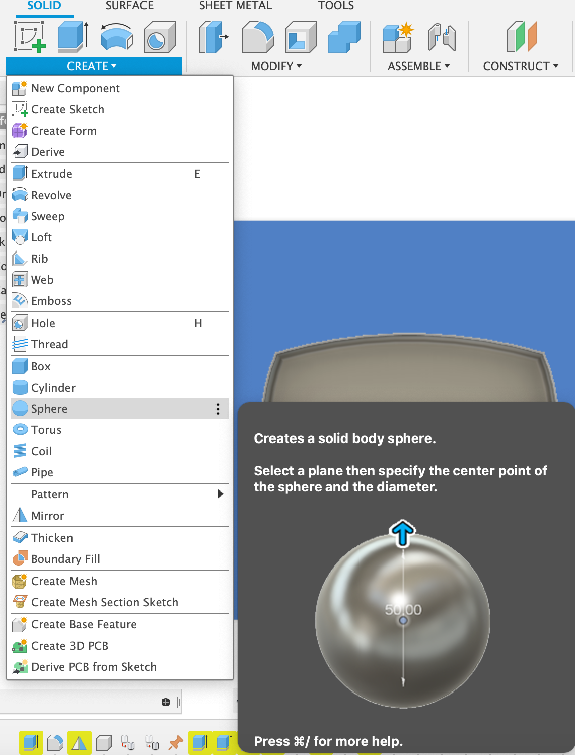
To create the registration pin, I used the sphere feature. To access the sphere feature, Create > Sphere:
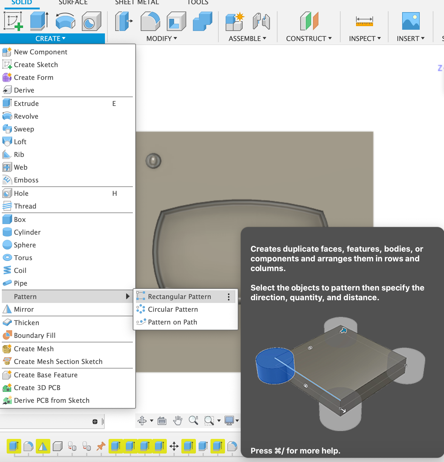
From there, I selected the rectangular patter (Create > Pattern > Rectangular Pattern) as I want to pattern the sphere onto the other three corners.
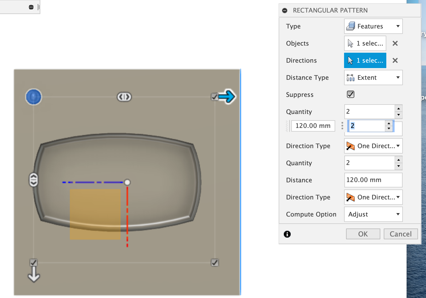
For the rectangular pattern information, I made sure that the Type is Features and select the Sphere cration from history, the Direction is the right line on the mold, the Quality is 2 for both ends.
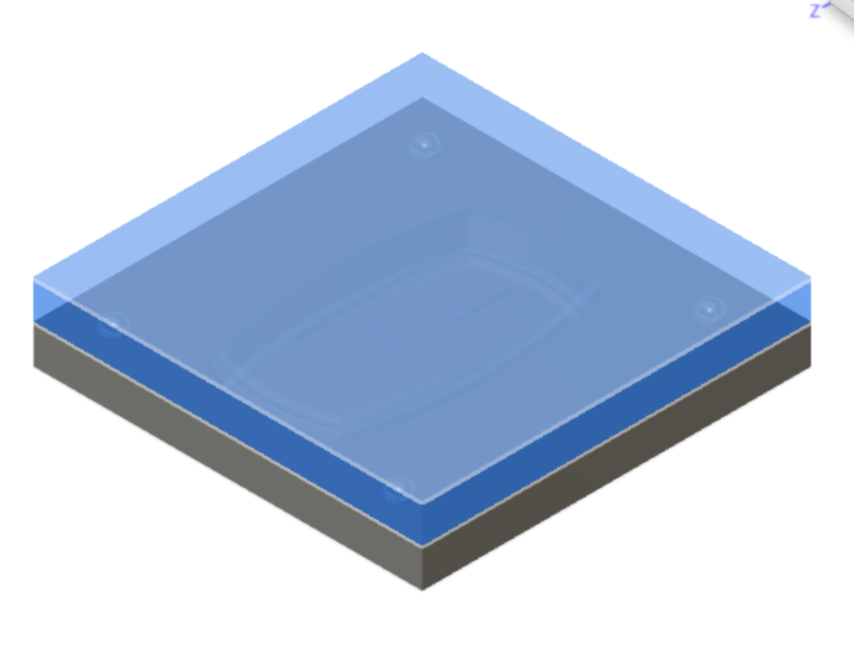
Now, I have to subtract the sphere from the top side of the mold so we can mill the mold. To start, I turned back the Top of the mold and changed its opacity to 50%.
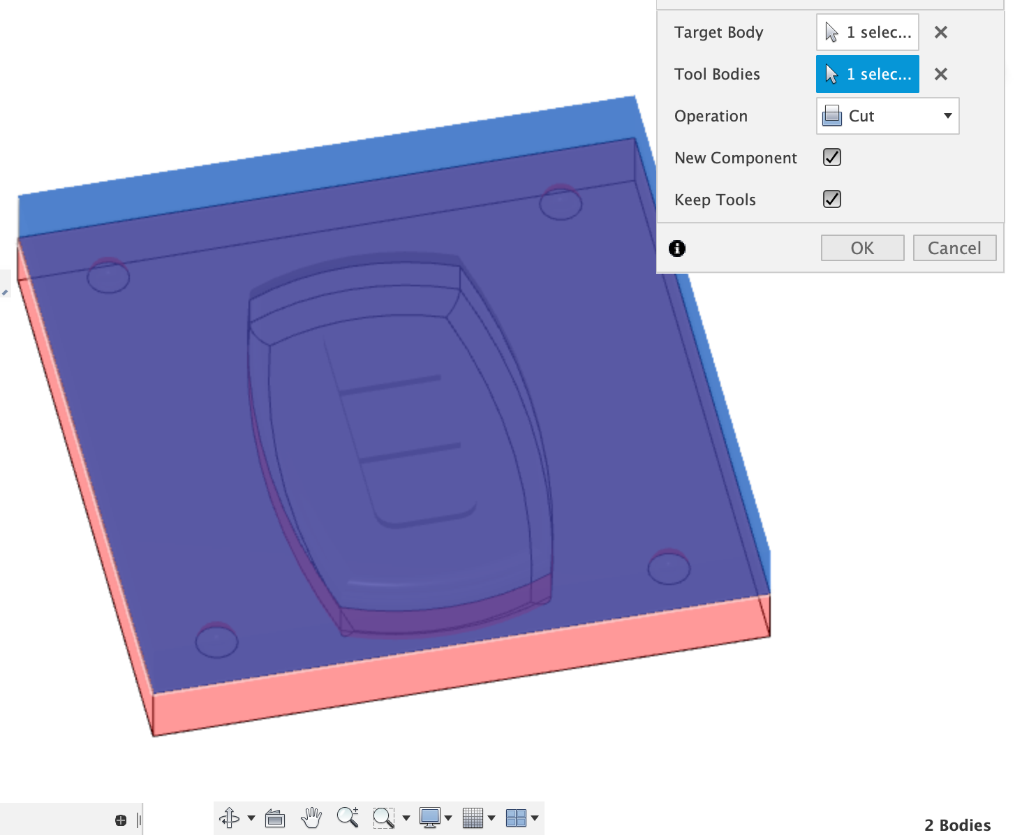
Then, I select the combine tool once again with the target body being the Top and the tool body being the bottom. I made sure the operation is set to Cut and New Component and Keep Tool are checked.
I turned the opacity back to 100% for the new component that was made from the Combine command.
To verify everything worked as expected, I hid the bottom.
Now we have both top and bottom of the mold both containing the registration spheres.
The next step is to create a hold to pour the material in. I decided to put the hole on the top of the surface. I changed the opacity back to 50% for the Top so that I can see what I’m doing.
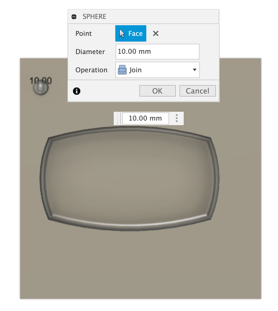
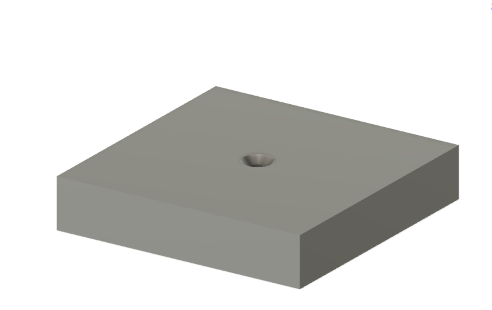
I selected Hole (Create > Hole) and placed it on the Top of the surface in the middle. I adjusted the Hole features:
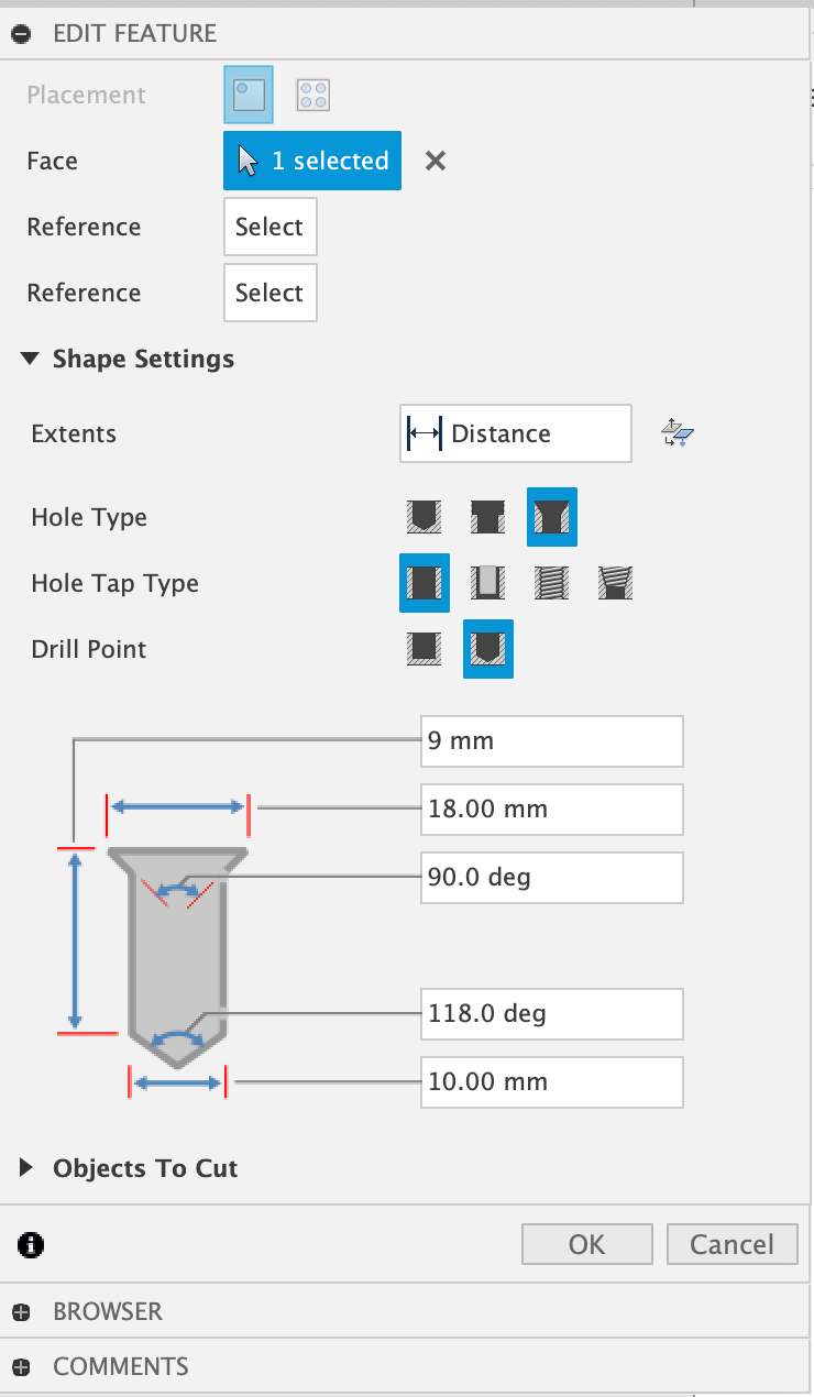
(Note: I decided to change the hole size to 10 mm)
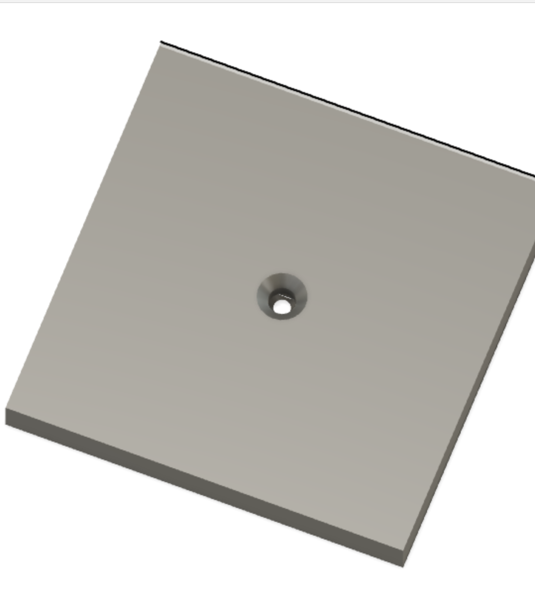
Now we have a hole to pour our substance into the mold.
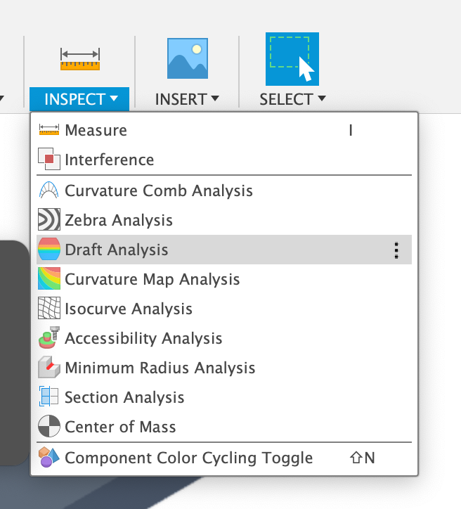
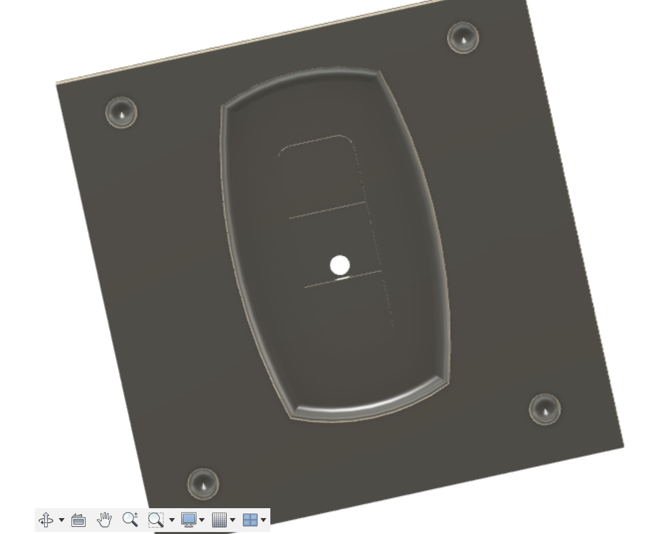
The last thing I wanted to do is check the draft analysis to see how well the object will come out of the mold. To start, I selected draft analysis from the Inspect drop down menu.
I selected the Body for body and the Top surface for direction (the top where the substance is being poured into).
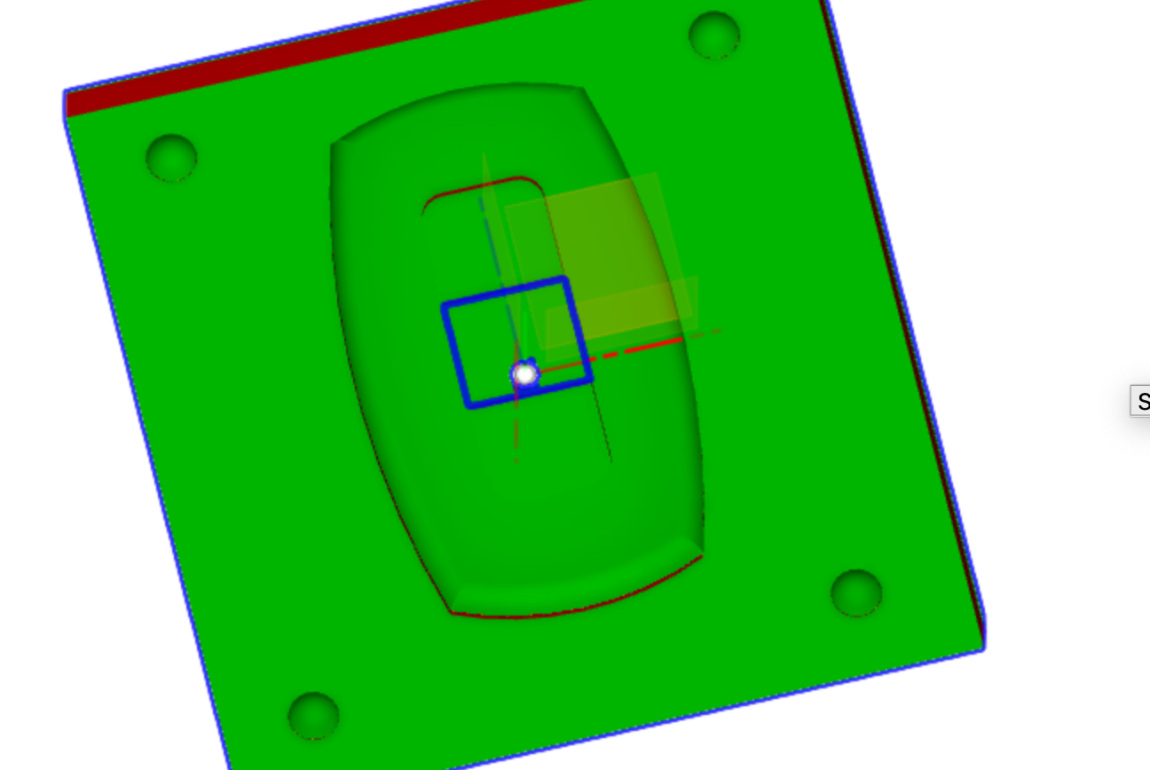
From the image, I might come into issues with the edges coming out of the mold as it can be indicated from the red color. But, this might be fine regardless.
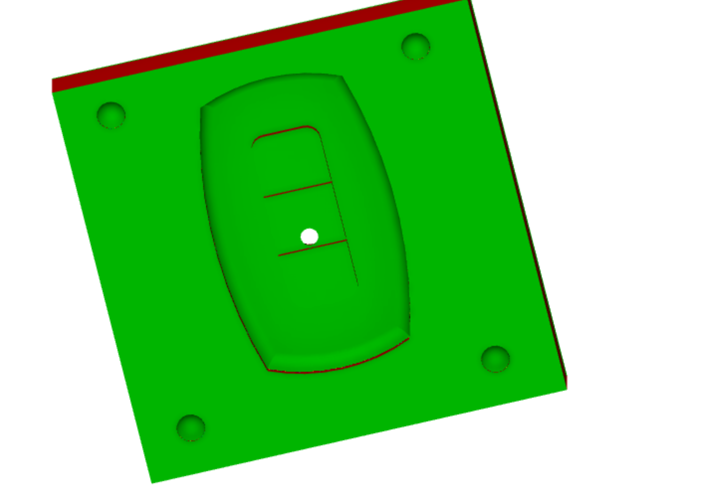
I repeated the step for the bottom.
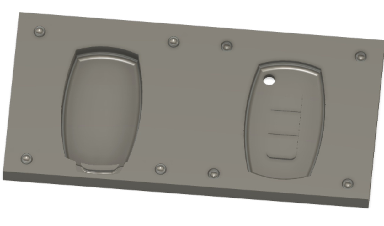
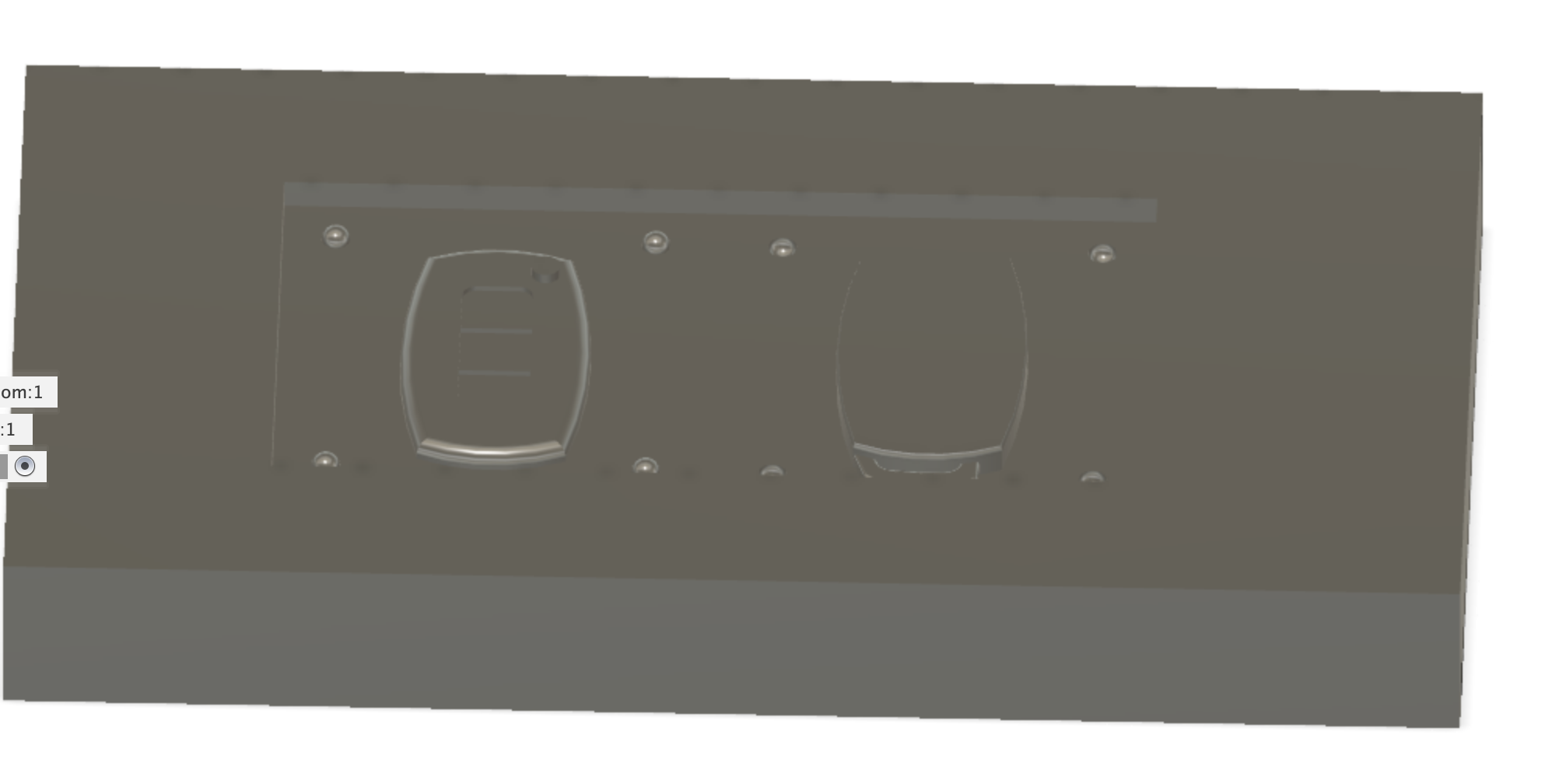
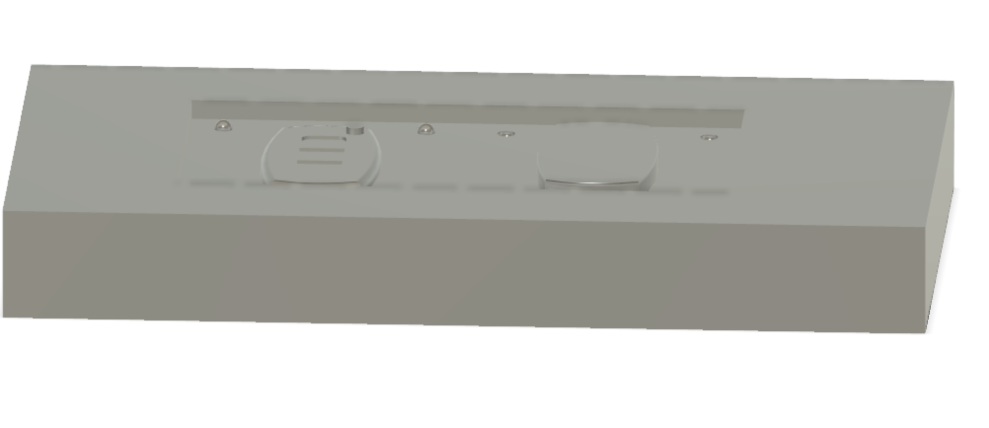
Here are some final Fusion 360 shots:
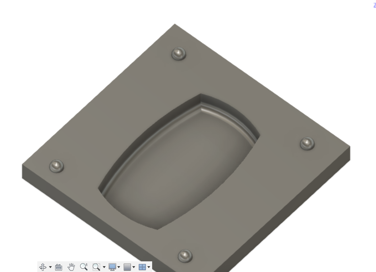
Note: I decided to add some last minute changes such as, I scaled my model down to be able to fit in on one wax block:
and I added a keychain insert on the design:
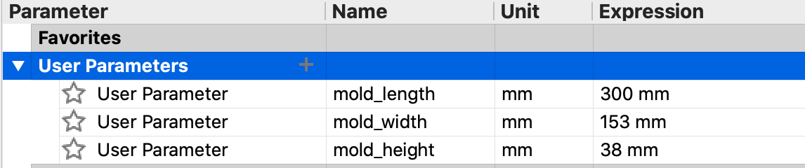
Next step was to create the wax I’ll be using to mold my design in Fusion 360. I started off by adding some parameters.
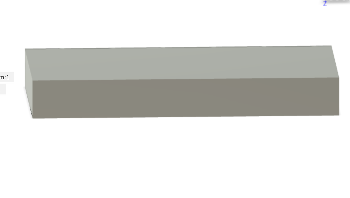
From there, I created a cube.
The next step was to have the two components side by side.