9. Embedded programming
This week I worked on:
- Previous Week
- Reading the datasheet for the microcontroller I was programming
- Exploring the datasheet for ESP32-WROOM
- Programming a Board
- Link To Group Assingment
Previous Week
Previous weeks, I needed to re-mill a board and solder the correct components onto it such as:
- Resistor
- Button
- Ground
- VCC
- UPDI
- LED (Light Emitting Diode)
- Resistor (value 499 ohms) Purpose: current limiting resistor
- Attiny412
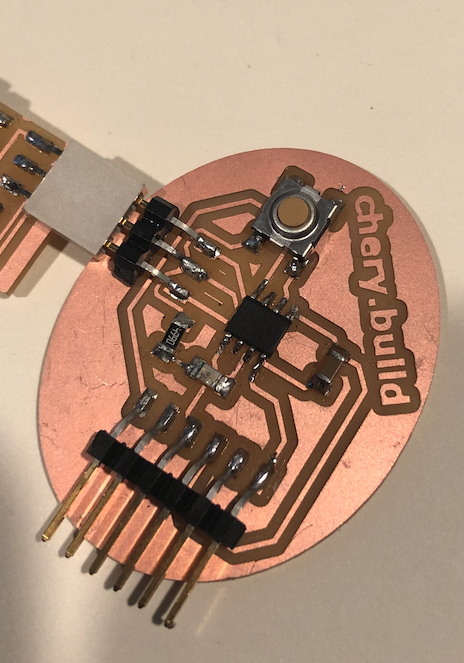
The end result came out like:
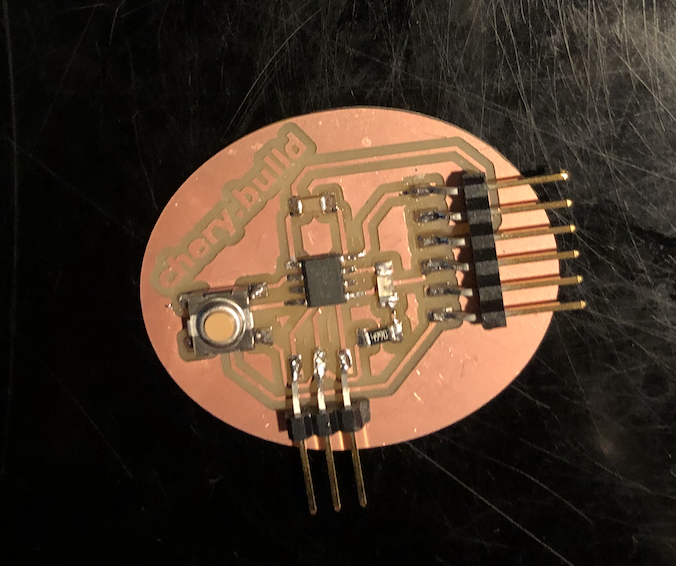
With the same board, I decided to program it to do something simple such as blink when the button is pressed. But, before I start the programming, I needed to read the Attiny412 datasheet.
Reading the datasheet for the microcontroller I was programming
I was able to obtain the ATTiny 412 datasheet from microchip. Microchip is a leading provider of smart, connected and secure embedded control solutions. You can also get datasheet from DigiKey as well.
First off, reading a datasheet is tough. There’s a lot of content and can easily get overwhelming. However, the point of the datasheet is not to read nor memorize the information but, to get a jist of what the microchip can do and how powerful it is. To help me read the datasheet, I found a blog How to Read a Datasheet from spakfun.
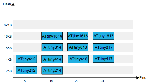
Scanning through the datasheet, there were a lot of information given. Some of the information that were given, I didn’t quite know what to do with it however, others seemed to be quite useful. For example, Figure 1-1. tinyABR 1-Series Overview gave me insight of the Flash Memory and Pins available for the type of ATtiny.
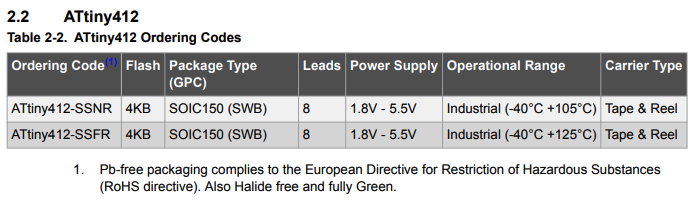
Another information that I’m able to use from this datasheet is the ordering code for the ATtiny 412:
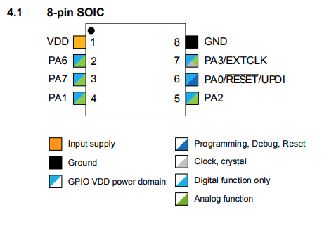
The 8-pin SOIC was another aspect of this datasheet that I can use to help me further understand how to work with the ATtiny 412:
In all, microchip datasheet is quite helpful in understanding what technology a person is working with. Though not all the information might be relevant for me, some which were pointed out in the images above will help in programming the ATtiny 412.
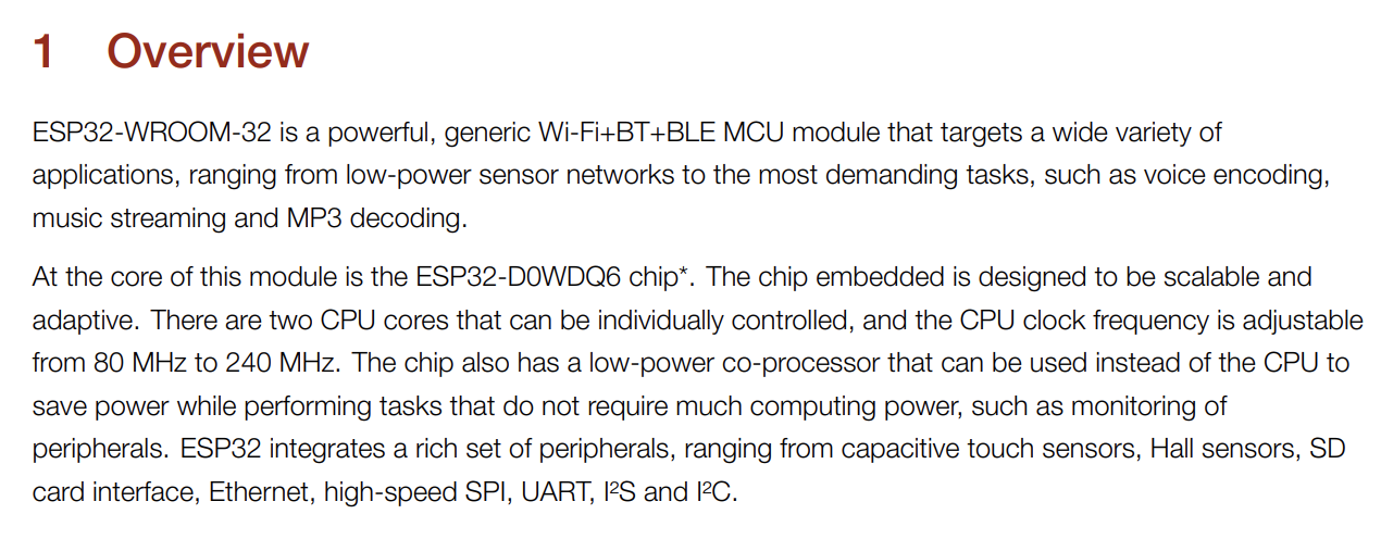
Exploring the datasheet for ESP32-WROOM
ESP32-WROOM is the micro-controller I want to use for my final project. That said, I explored the ESP32 datasheet. In the datasheet, I found the overview of the chip helpful. The overview can be found on page 6:
I also found the pin out for the ESP32 quite helpful:
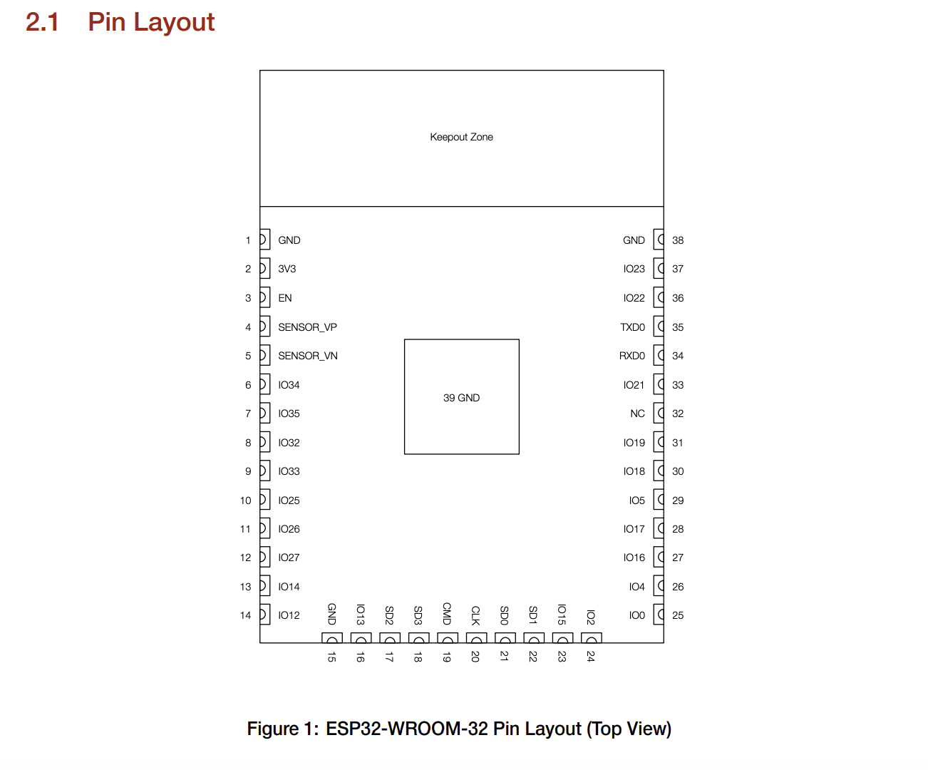
Along with the pinout definition which can be found on pages (8-9).
Programming a Board
My goal was to create a program that causes my board to light up every time I click the button. When I click the button, the LED would turn on until I click the button again, where the LEd would close. To get the programming working, I needed a:
This adapter was inspired by the:


I used the following files to created the above adpater:
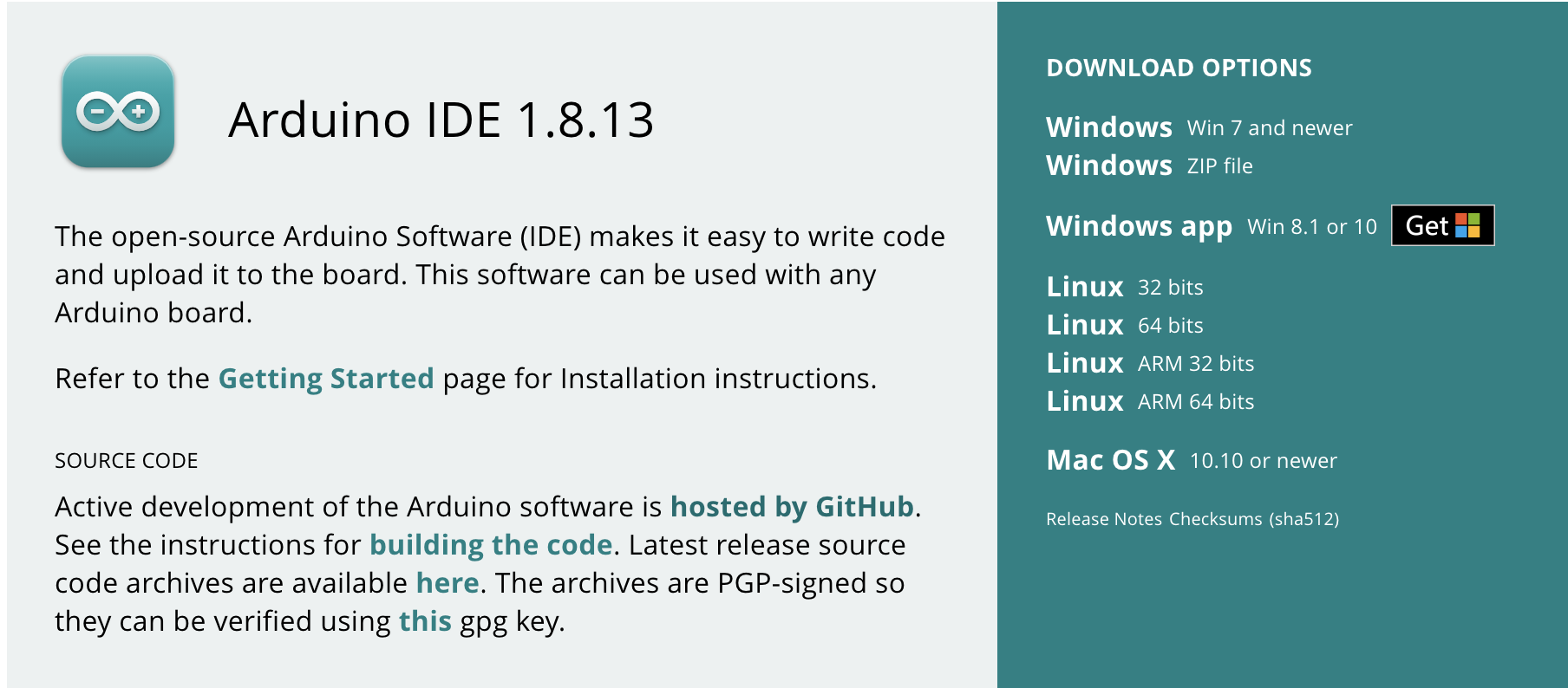
Once I created the adapter, I downloaded the Arduino IDE to begin programming.
To program my board, I needed to first understand how the UPDI adapter, my PCB board, and the FTDI adapter works. I reached out to one of my instructor, Greg Buckland, where he explained the process of embedded programming. In short, the takeaway I gained from our sessions were:
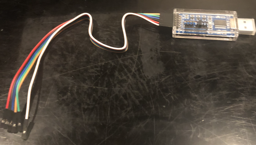
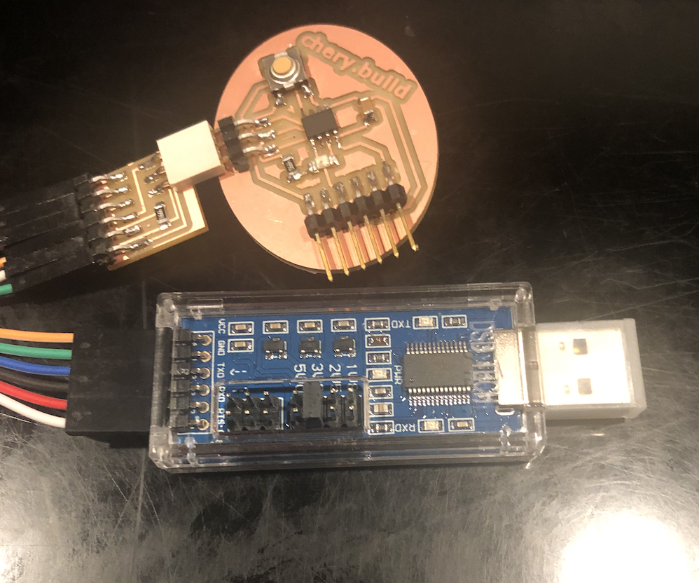
The above image is an FTDI adapter with some Male to Female Jumper wires. FTDI stands for Future Technology Devices International and it is used to establish communication with your board/MCU through your computer. The main reason we use an FTDI adapter is because our boards do not have USB support and the FTDI adapter provides that support. External FTDI adapter has the ability to talk to your PCB board. When using the FTDI adapter, we focus on VCC, GND, TXD (Transmit), and RXD(Receive). More information about its usage can be found here -> Link
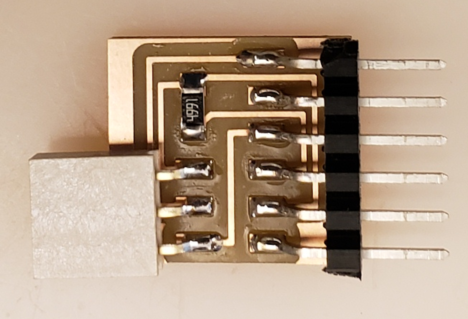
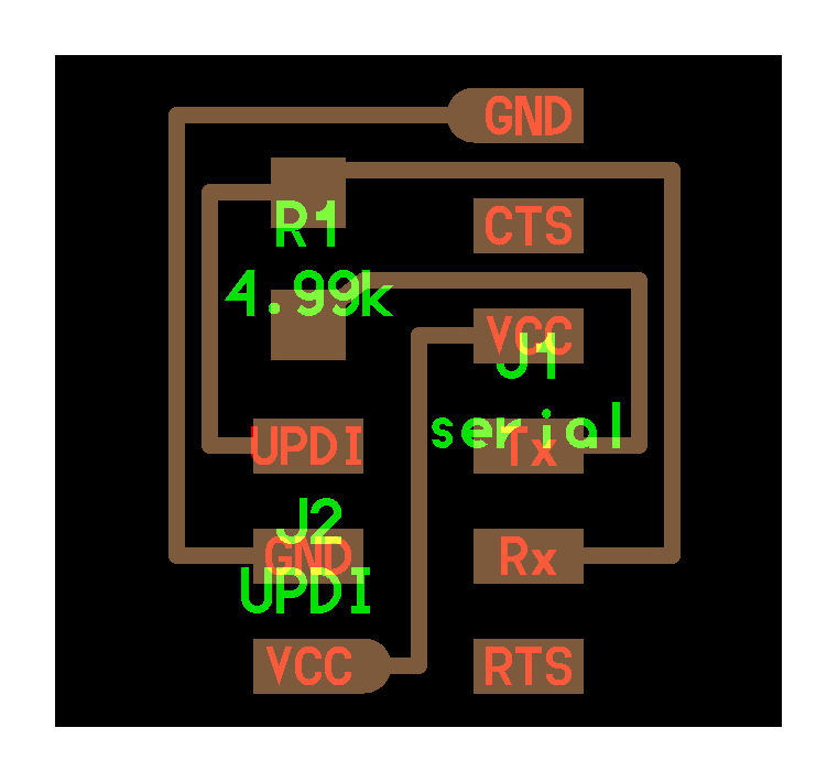
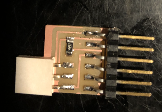
The above image is a UPDI adaptor. UPDI stands for Unified Programming and Debug Interface and it is used to program the board. The three sockets allows you to program and power the board.
- We use the jumper cables to connect the FTDI adapter to the UPDI adapter. It is important to verify that the pins match. For example, we must match the FTDI adapter’s VCC, GND, TXD, and RXD to the UPDI adapter’s VCC, GND, TXD, and RXD.
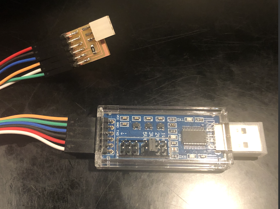
- Now, I can connect the UPDI adapter to my PCB.
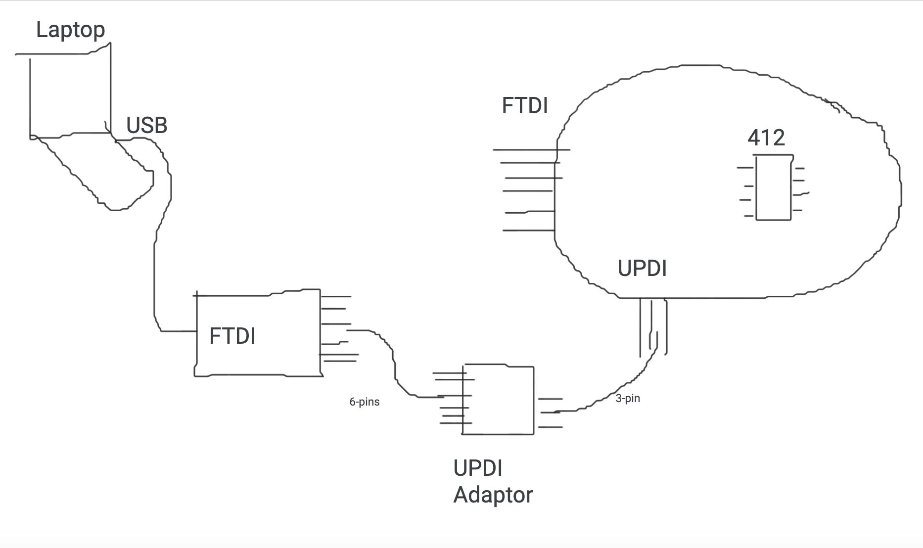
Once all three is conncected, we can program the PCB. Below is the diagram of how the communication will occur between the FTDI adapter to the UPDI adapter to the PCB.
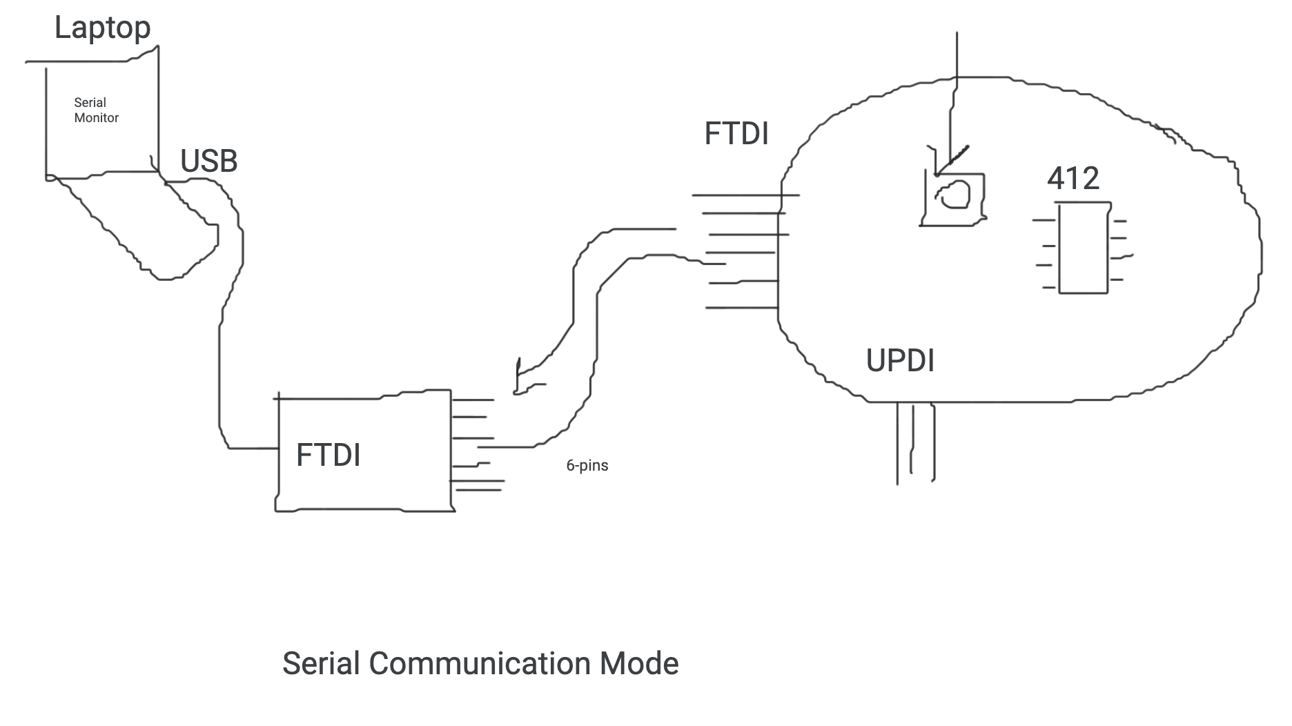
Additionally, below is the diagram for serial communication mode:
Though I downloaded the Arduino IDE, I decided to test out the Arduino Web IDE and explore its functionality.
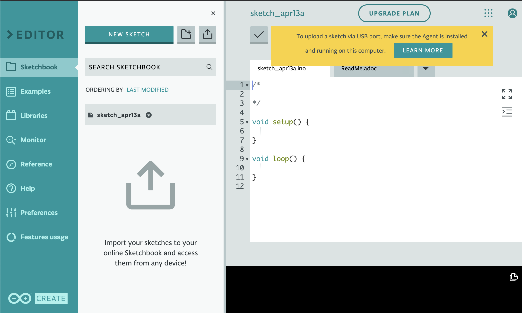
Unfortunately, after testing the Arduino Web IDE, I determined that it will not work and reverted back to the Desktop application.
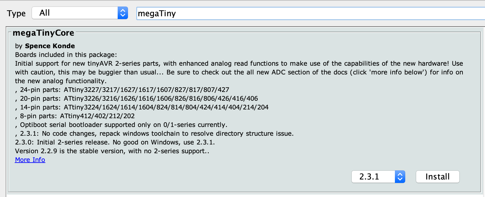
To begin the programming the ATTiny 412, I need to install a library called megaTinyCore. I used the Programming the new ATtiny from Arduino using UPDI [Beginner Tutorial] for additional guidance. To install the library on the Desktop application using a Mac, I navigated to Arduino > Preference > Additional Boards Manager URLs:

The next step was to install the megaTinyCore from the board manager manager by Tools -> Boards -> Boards Manager…
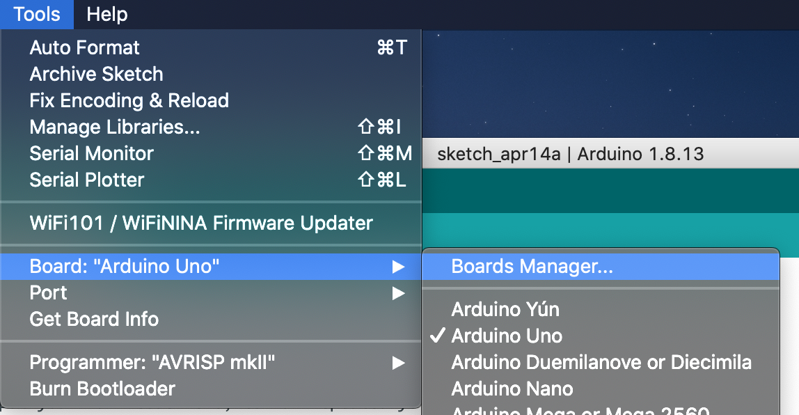
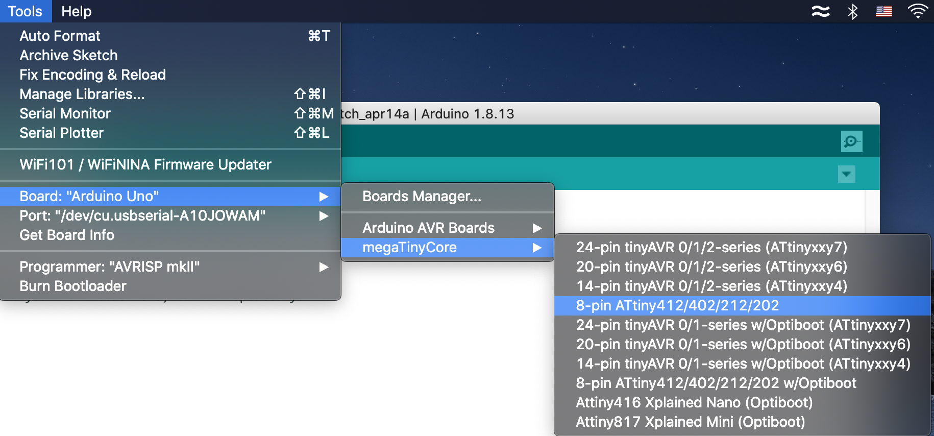
Now, we can start programming the PCB board. I connected my FTDI adapter to my computer and went to select my microcontroller by navigating to Tools > Board:
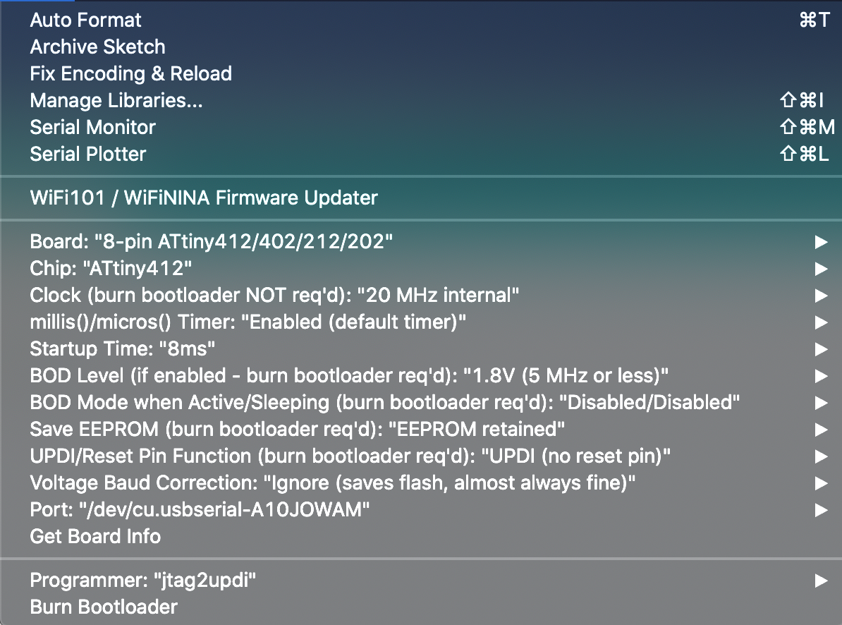
Additionally, within the same panel, I verified if my chip was correct. I am using a ATTiny412. Next, within the same panel, I sent the programmer to jtag2updi. Below is the result of my configuration:
Now, let’s test if the uploading works. I received an error:
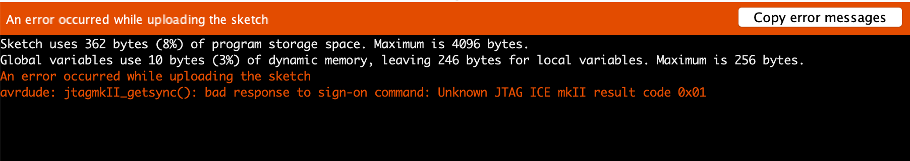
I’m not sure what this error mean however, when researching an explaination, I found that this error is due because of the AVR is running at 1MHz. The JTAG frequency is too high. Reduce to 200kHz or so. However, this did not seem to fix the issue. Upon further investigation, many people suggest ignoring the message and it should not stop you from porgramming. So I continued to see if anything would happen. I ran an example code from the Arduino library. The code was called Blink Example.
The issue persisted. I went to seek help from my instructor and they mentioned that the issue is due because I am not using a JTAG ICE programmer and I should be using pyupdi style.

After that changed, I decided to test it by checking if uploading works without any errors occuring.
I received another error:
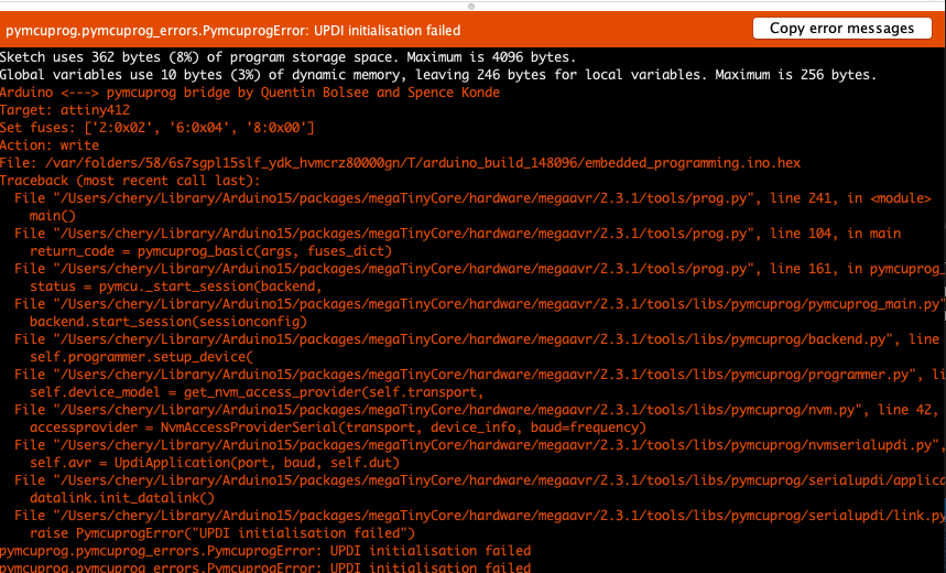
So, I decided to debug this error by confirming if my wires were connected correctly from the FTDI adapter to the UPDI adapter.
The connection was establishe. Additionally, I added a basic code that blinks the LED:
 int LED_PIN = 4;

// the setup function runs once when you press reset or power the board
void setup() {
  // initialize digital pin LED_BUILTIN as an output.
  pinMode(LED_PIN, OUTPUT);
}

// the loop function runs over and over again forever
void loop() {
  digitalWrite(LED_PIN, HIGH);   // turn the LED on (HIGH is the voltage level)
  delay(1000);                       // wait for a second
  digitalWrite(LED_PIN, LOW);    // turn the LED off by making the voltage LOW
  delay(1000);                       // wait for a second
}
I used CLoudConvert to convert my recorded video to mp4 and then used ezgif to cut down the video size. The result was the video below:
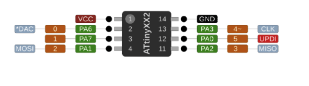
The LED_PIN was set to 4 based on the ATTiny412 pinout. THe LED pinout on the ATTIny412 was on 7th leg. Using the image below, I was able to find the LED pin to be either PA3 or 4. However, the image above indicates the leg to be 13. I wasn’t quite sure why but, I did use the values associated with 13.
Now, to plug the FTDI adapter and upload the code.
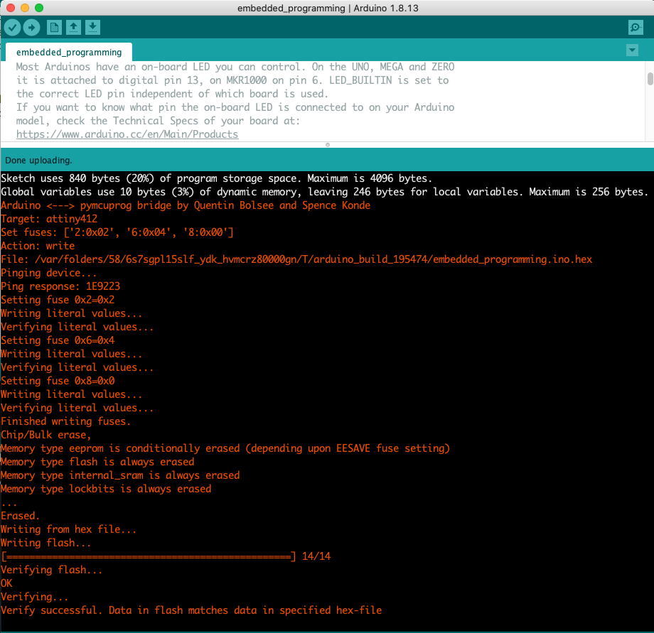
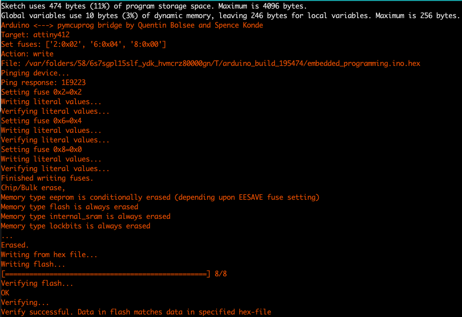
The code was uploaded successfully.
After the successful blinking, I wanted to have some button interactions. Remembering my goal, I wanted the LED to lit up every time I click the button. When the button is press, activate the LED. When no button is press, do not show the LED.
The first process is to identify the pin for the button which will be either 0 or PA6.
// Set pin number
 const int LED_PIN = 4 ;
 const int BUTTON_PIN = 0;

 // variable will change base on button state
 int button_state = 0;

// the setup function runs once when you press reset or power the board
void setup() {
  pinMode(LED_PIN, OUTPUT);
  pinMode(BUTTON_PIN, INPUT);
}

void loop() {
  // read the state of the button
  button_state = digitalRead(BUTTON_PIN);

  // check if the button is pressed. If it is, turn the LED on else, off.
  if(button_state == HIGH){
    // turn LED on
    digitalWrite(LED_PIN, HIGH);
  } else {
    // turn LED off
    digitalWrite(LED_PIN, LOW);
  }
}
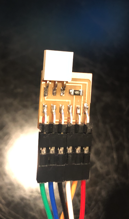
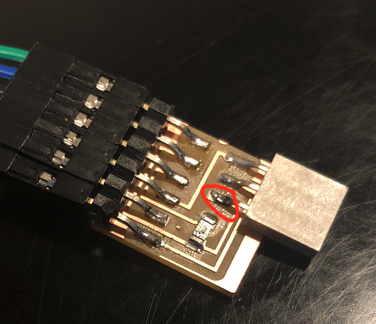
After several trail and errors, I noticed that there was a loose solder on the UPDI adapter. This loose solder caused my code upload to fail. When I press down on the weak solder, the code would get uploaded without fail. But when I do not, the upload would fail. To fix this issue, I need to resolder that part of the pin.
Area that needs to be resoldered:
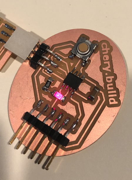
Now, the button is a success:
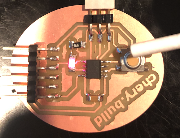
Button not pressed:
Button pressed:
Short video:
Link to Group Assignment
This week group assignment was to compare the performance and development workflows for other architectures.Group’s Page