8. Computer controlled machining
This week I worked on:
- Learning Vcarve
- Designing a Worktable on Fusion 360
- Designing Modular Shelf on Fusion 360
- Milling & Assembling The Modular Shelf
- Link to Group Assignment
Learning Vcarve
I started this week learning about Vcarve. Vcarve is a CAD/CAM software with 3D and limited 2D functionality. Thanks to Spencer Mewherter’s video (link) where he provides a ~40 minutes tutorial of how to use Vcarve for the shopbot we are using to make something big. We use Vcarve to create the toolpath for the Shopbot.
In Vcarve, we first start off by selecting “Single Sided” under Job Type.
In Job Size, our width, height, and thickness matched the width, height, and thickness of the full-size of the machine bed. That said, the shopbot at Dassault is 96.0 inches (width), 48.0 inches (height), and 0.75 inches (thickness).
In Zero Position, we selected “Material Surface”. This is to give our design a reference point.
In XY Datum Position, we set the x & y to 0.0.
In Modeling Resolution, we set it to “Standard (fastest)” and in Appearance, we set it to “Canadian Maple”
After you finish setting up, you’ll be taken to a new page to work on the path. It is important to be familiar with the 2D tools on the left.
We first import a file. We often want to do the design work in another file and export a 2D file that we will be working on in Vcarve.
DXF and PDF are the best export file. One of the major issue you’ll have is with scaling. The way to address this is before you export, make sure you give yourself a scale box around your entire piece. Also, it is good to check if all your vectors are closed. To check if your vectors are closed, you can watch at 07:24
The next thing we want to do is to see if we want to do any modification to our toolpath - 09:28. So, if you want parts that fit into each other, we have to deal with them by doing a fillet. There’s a couple of ways of doing this. You can round the corners on the piece that you’re fitting into it. Another option is you can overshoot your corner so that the cutter clears it and then another swuare edge shaoe can fit into it. The radius of your tool is the diameter of your fill. Because these are dependent on your tool size, it’s important to know ow to edit these on the fly in the software.
Because we are using vCarve in an open space where everyone has access to it, it is good to always verify all of the settings whenever you create a toolpaths by verifying all the speeds. and feeds.
Using the shopbot allows you to climb male or demale conventionally. This refers to the direction it oves aroun the ckub slimbing and you get a better surface finish. Conventional milling puts a little bit, less force on the machine and the material we’re working in. Ramping plunges refers to while the tool is moving downward, it’ll also move laterally. With some tools, it’s important to know that some tools don’t like to plunge straight down and you can see that in some geometry.
In Machine Vectors 23:12, you are given some options to cut outsite of your line, cut inside of your line, or cut directly on your line. <- This is something that you manually do. Under the same section, you are given Allowances offset and that is where you can overshoot or undershoot your line and you can enter a negative or positive.
In Add tabs to toolpath 24:06, you can set the value for a tab. Here, we made the length value 0.25 inches and thickness value 0.125 inches. Tabs are when you leace a small piece of material behind so that your workpiece doesn’t become destabalize. It is very important and annoying.
IN Add Tabs Automatically, in here, you can automatically add your tabs of manually place them. When placing them, think about the best place to suppport your work. Also, think about the easiest place to clean up. Avoid putting your tabs on curved elements in a geometry because those are a little harder to sand off. You want to make sure that your pieces are not destablize and come loose.
It is always important to verify in the preview your selected path
So, the next step to Export Your G-Code to another machine 26:29. But before you export, it is nice to do a few checks: - Make sure you have your tabs - Make sure you’re cutting on the right side of the line - Make sure your geometry is correct - Check your machine time
Checking your machine time is good for catching large errors, specifcially unit errors and feed rates.
To export, go into Save Tool Path > Visible toolpaths to one file > Select the first pocket we are going to cut (we are going to manually cut the toolpath. It is recommended to review each toolpath slowing) > Select a Post Processor [ShopBot TC (inch)(.shp)] > Check off Output direct to machine*
Designing a Worktable on Fusion 360
I have a lot of boxes in my apartment and it’ll be nice to have a place to store and open packages. That said, I wanted to create a workbench to be able to store, open packages, also do some projects on. So, the goal was to create a workbench. I found a Youtube video of a workbench that was created using Fusion and I thought this would be a nice place to start - Link.
I started off my design looking for some additional inspiration on Pinterest. I searched for Plywood Workbench. The result were quite surprising and interesting. The next step was starting my design by following the tutorial on youtube.
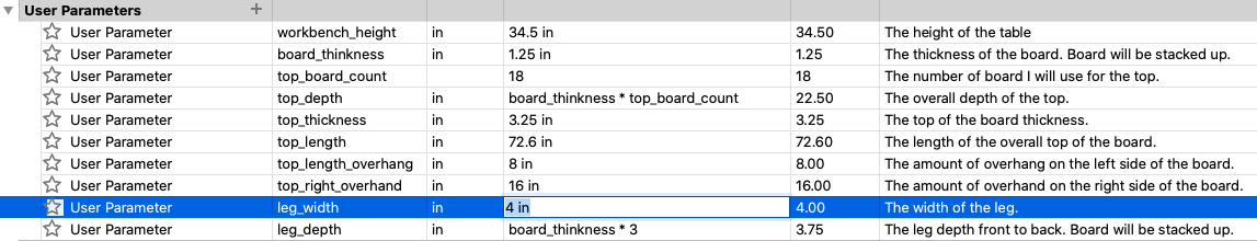
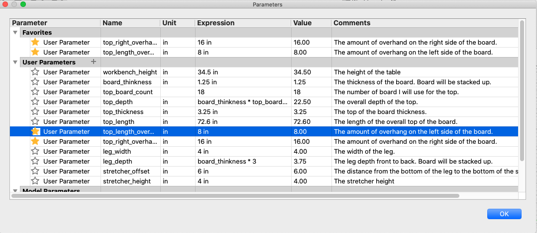
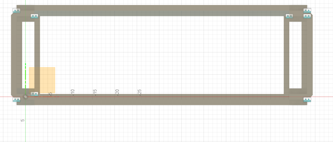
I started with creating parameters.
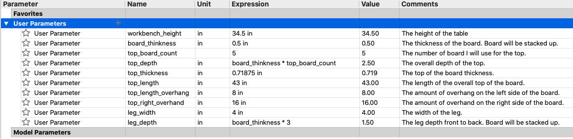
I added some comments on each parameters as I thought it would be good documentation.
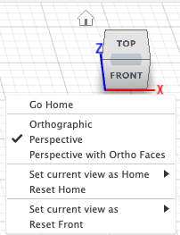
Once I finished my parameters, I changed the camera orientation by going towards the cube on the top right of Fusion 360, select inbetween the Top and Front (Top-Front Edge) and selected the dropdown to change it into Perspective.
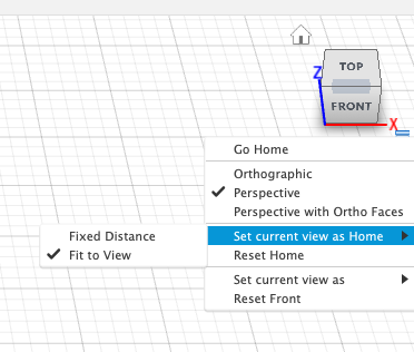
and then, doing the same process to change the perspective, I also changed the Set current view as home > Fit to view.
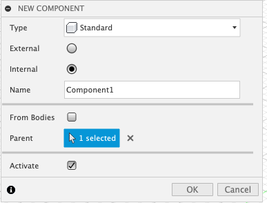
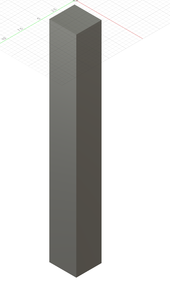
I created a component called “Front Left Leg” to begin my design.
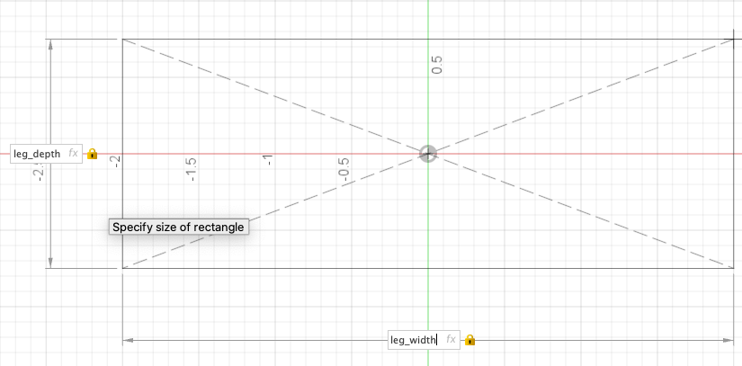
In the component, I then created a Sketch on the Top plain. I chose to start with a Centered Rectangle
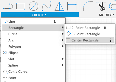
and from there, I used parameters to set the depth and width.
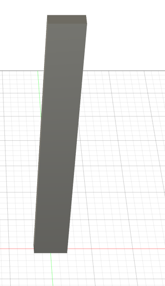
After I created the length of the leg, I extrude the leg and set it to height_of_workbench - top_thickness
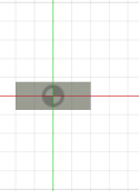
I created, on the top of the surface, a new sketch.
Side note, I decided to change my parameters to make it fit the video exactly. Towards the end, I think I’ll switch once I see the final design.
The result of my change led to:
Now, after my parametric changes, I continued with my design. I added the board thickness which are the 3 boards that I will combine on the top to make the top thick.

From there, I extruded the middle to the top thickness:
I added two parameters: - stretcher_offset - stretcher_height
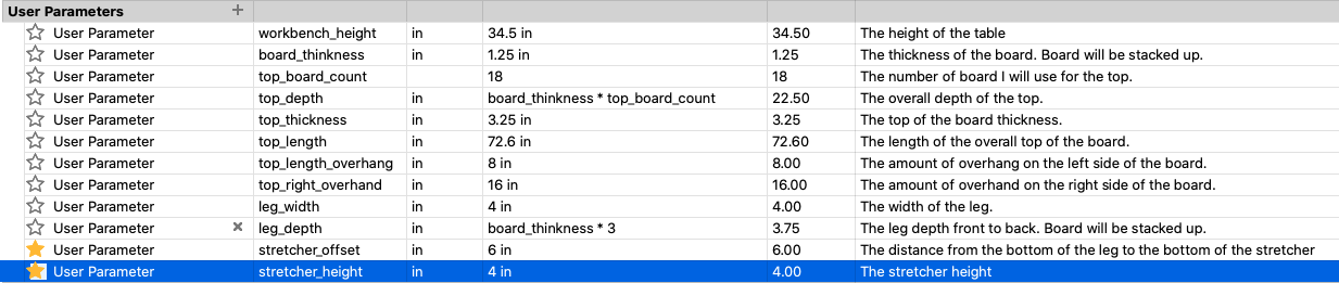
I starred them to indicate that those parameters were added. I removed the star.
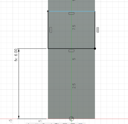
I created a new sketch on the face:
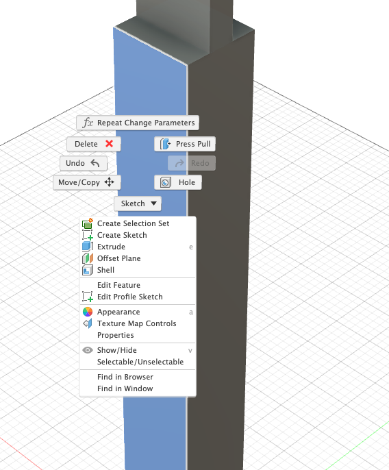
On that face, I created a rectangle and added the dimension from the bottom of the sketch to the bottom of the rectangle. The dimension was the stretcher_offset:
Right above the stretcher offset, I created the stretcher height:
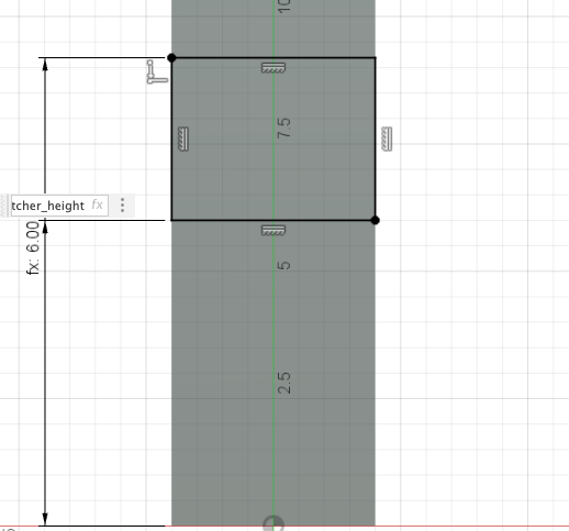
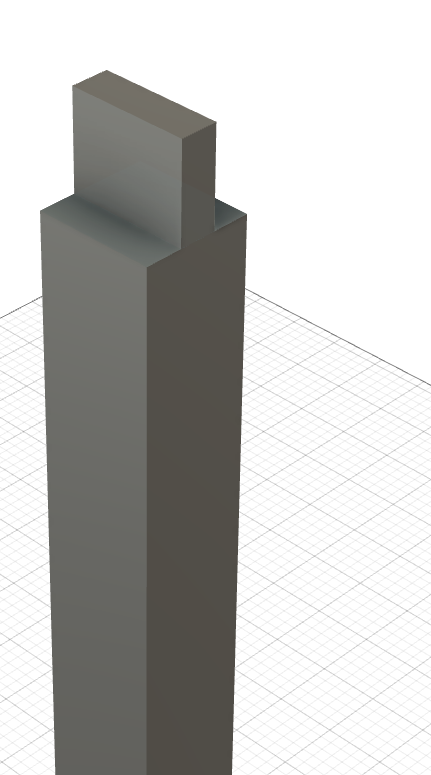
Escape out of the stretcher height and extrude it -board_thickness:
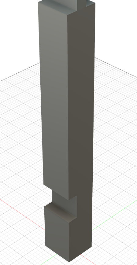
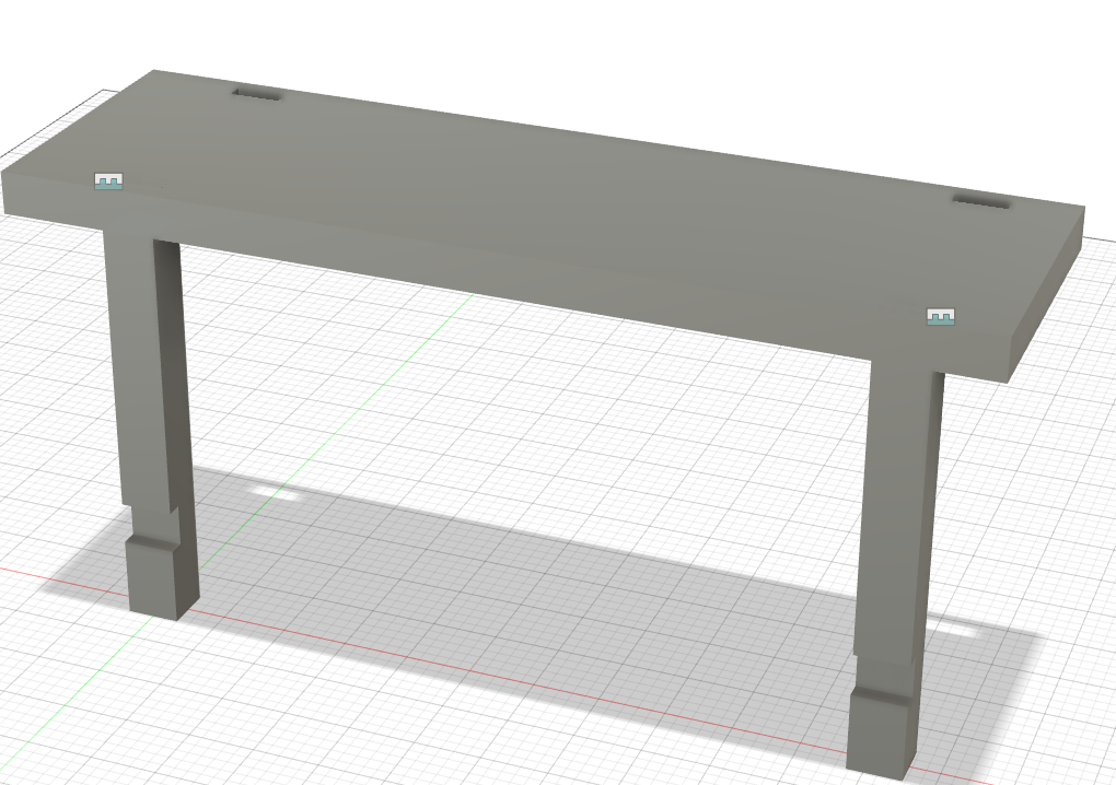
Now, we have a completed leg with a out lap joint and tenon.

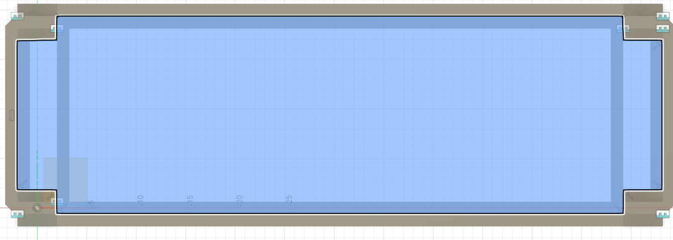
Next, I started working on the top. I started off by hiding the leg so that it won’t distract me. I reactivated the the scene component. Then I created a new component for the top anc alled it “Top”:
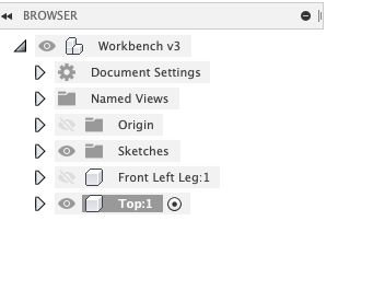
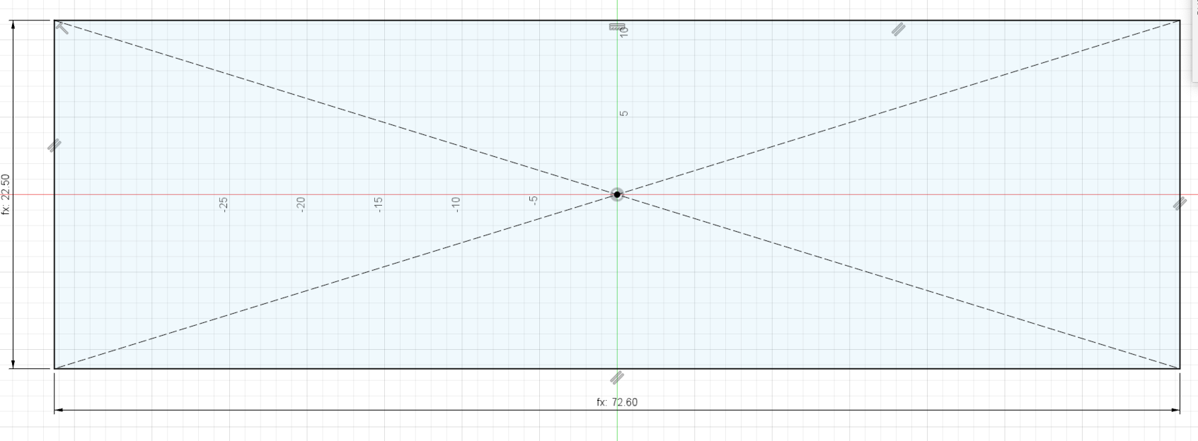
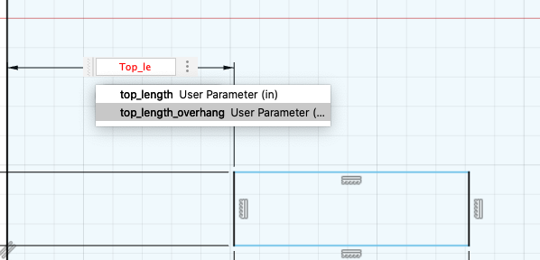
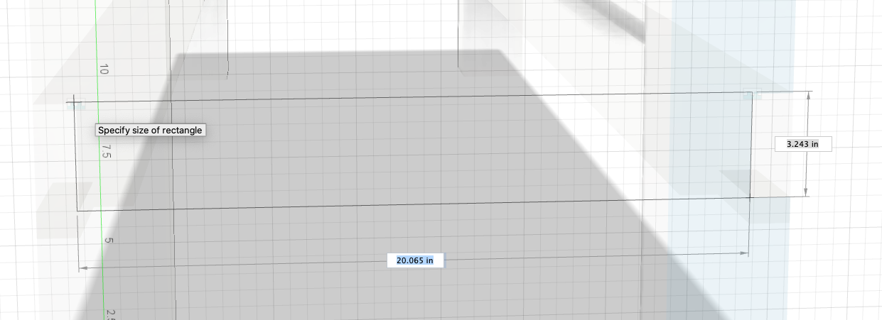
I selected a “Top” plain and strted with a centered rectangle. I made my top width equal top_depth and my top length equal top_length:
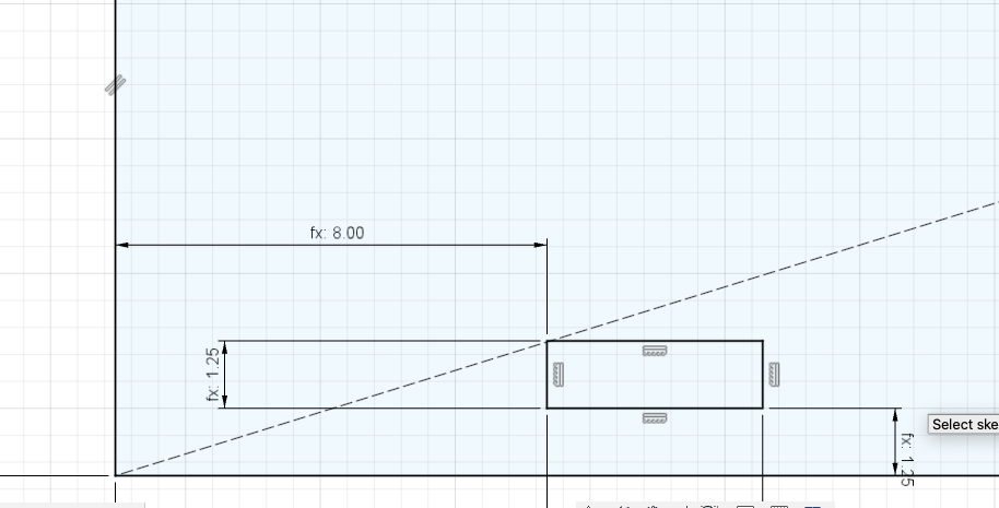
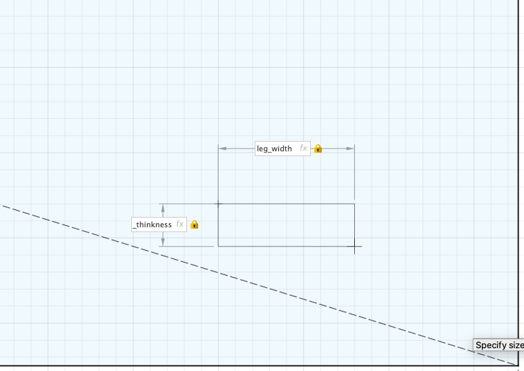
I created another rectangle with a width of board_thickness and a length of leg_width. (This was because I wanted to work on the front left front-left mortise.) I added dome dimentions:
Doing this added constraints to the mortise.
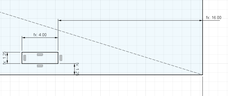
Afterword, I went toward the right to work on an another mortise where the width was board_thickness and the length was leg_width:
Afterwards, we do the same thing that we did for the left side mortise:
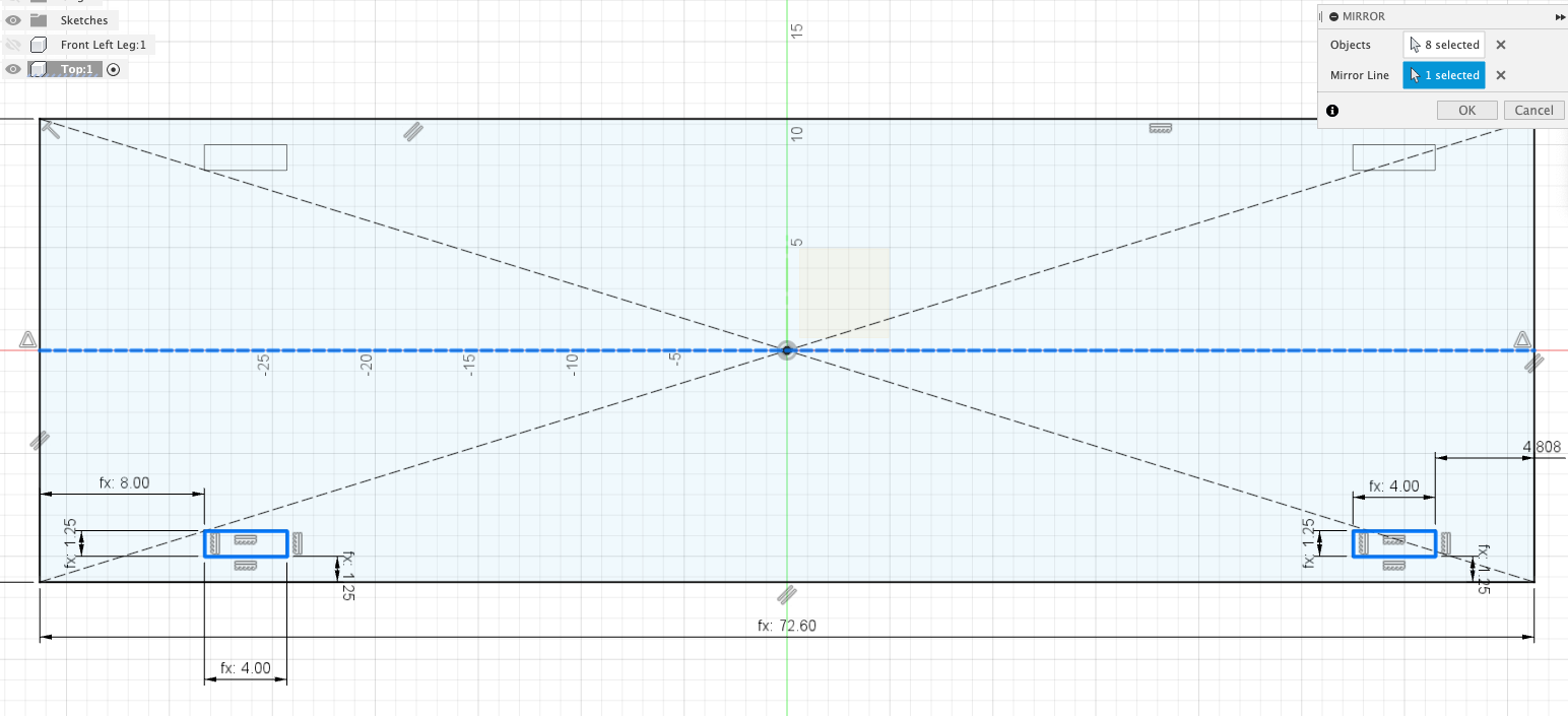
Now, instead of doing this two more times, I mirrored the bottom mortises to the top mortisies. I did so by creating a midpoint line to mirror the mortises across. (The midpoint are denoted by the blue triangle)
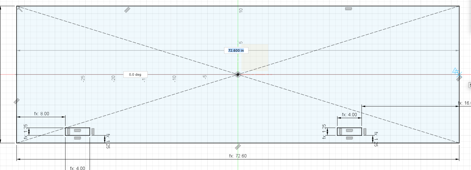
This created a new line for us to mirror the front mortises to the rear. But, as a result of using the line tool, it splits the top to two separate pieces. So to fix this, I selected the that line and just hit ‘x’ to turn it into a construction line. As a result, now it is one whole piece.
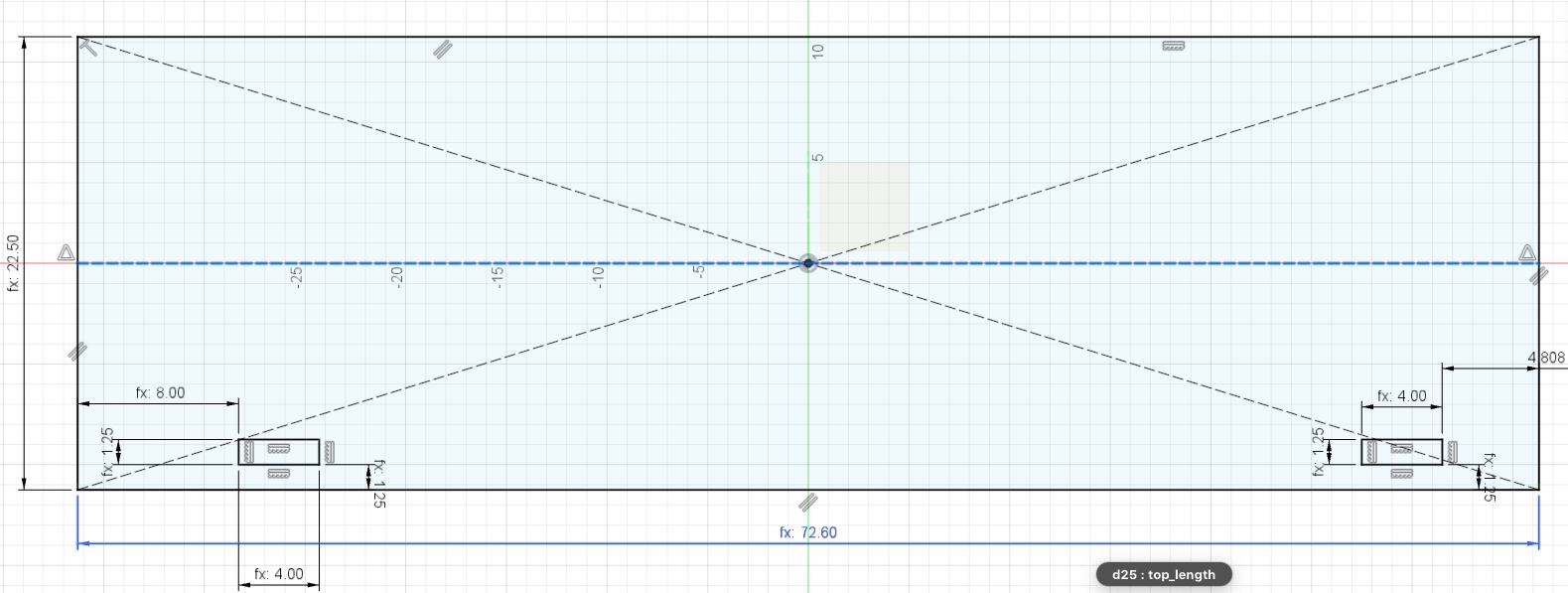
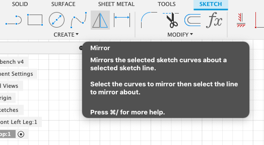
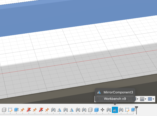
So, to mirror the mortises, I go to the Sketch Tool bar and select Mirror:
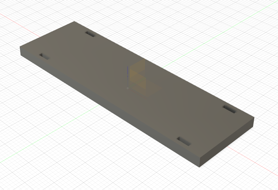
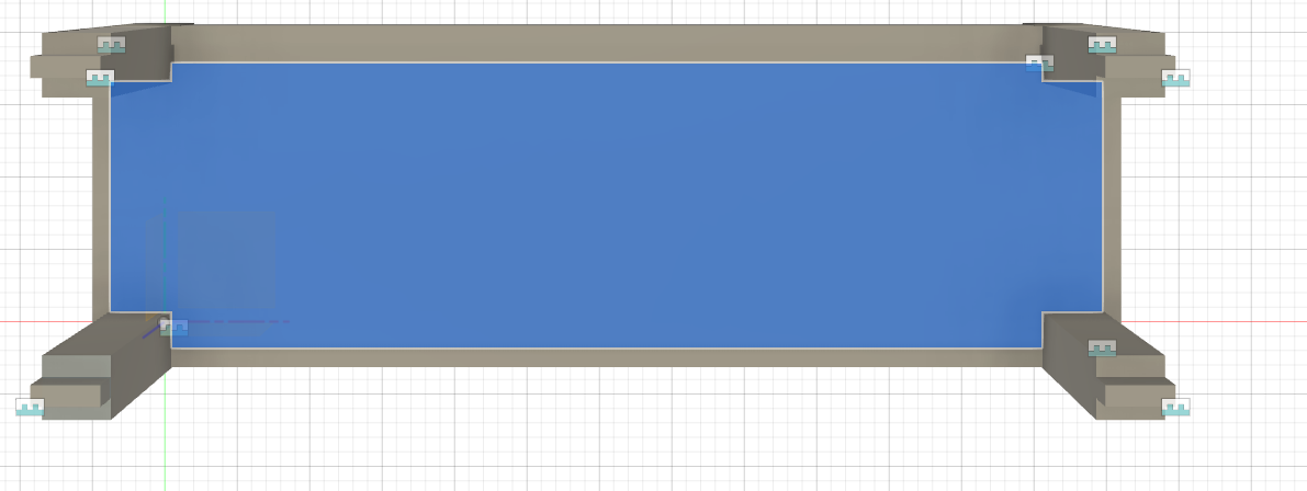
Next we select and extrude the top to the top_thickness:
Now, if I want to make some changes to the design, I am able to do so in the function view:
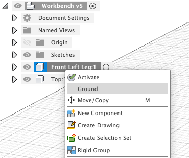
Now, it is time to do some assembly. I started bby activating the main scene component and unhide the front leg. I right-clicked on the “Front Leg” component and selected ground -> this kept the component in place and keep from moving.
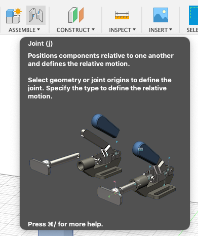
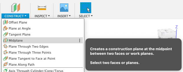
Now, to create joints to assemble. I start of by going to the “ASSEMBLE” section and selecting “Joint”:
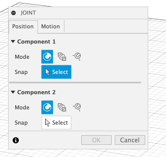
I started by selecting the first joining component:

Then I selected the second joining component:

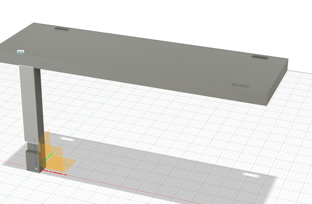
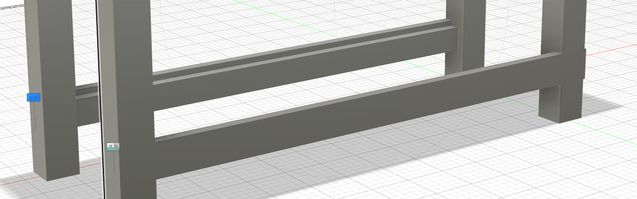
Combine, it looks like:
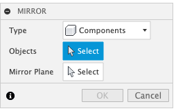
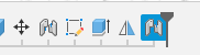
Next, I went ahead to mirror my front left leg to create my front right leg. I done so by selecting “Mirror” and instead of the type being Faces, I selected Components. Selecting Components will allow us to pick the whole leg component.
Once I made my mirror, I selected j for Joint to join my mirror to the table top:
Once I had two legs, I was able to make another mirror:
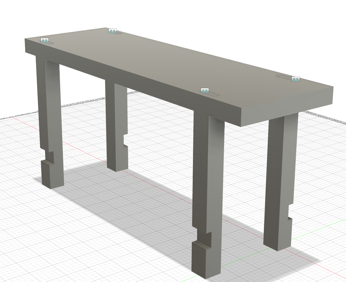
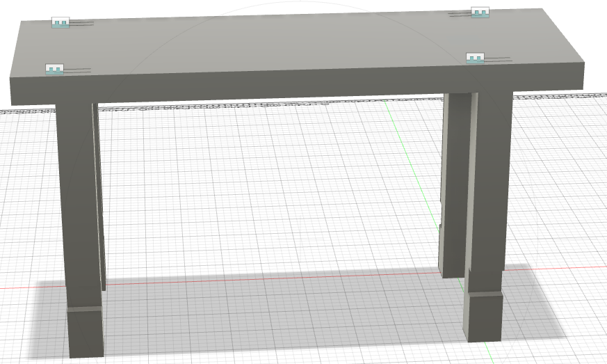
To ensure everything worked correctly, I changed the top_length parameter to 5‘4” and the result was that every changed accordingly.
So, now I renamed the components to an appropriate name that is a good descriptor of the component.

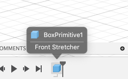
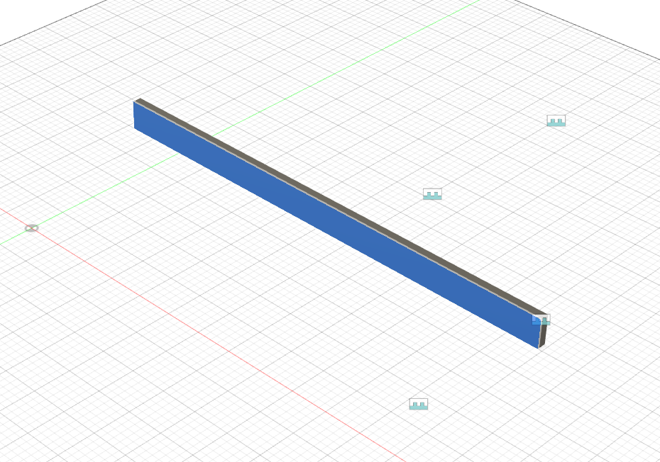
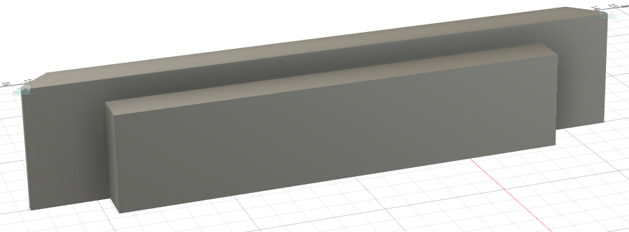
Now to start working on the top stretcher. I created a new component called Front Stretcher and, within the component, I created a 3D Box:
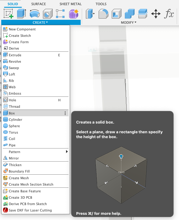
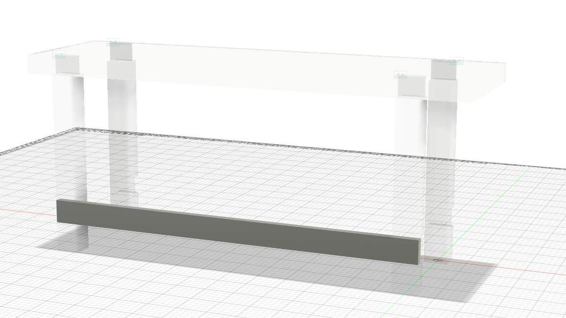
I created the 3D Box inside of the lap joint and dragged it to the other lap joint
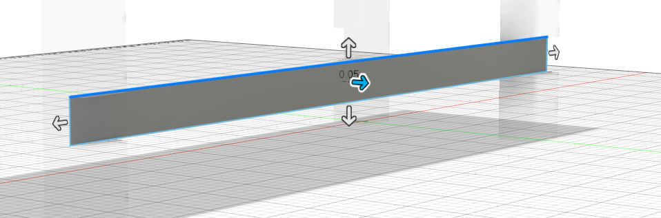
and applied the following input:
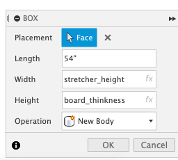
Note: I hardcoded the length but, I will add the parameter.
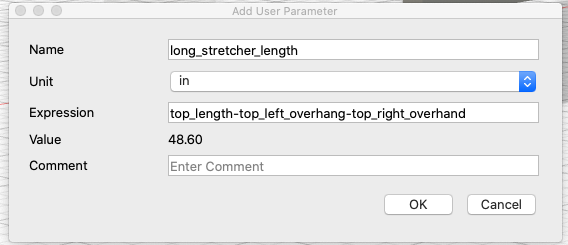
*Note: there length did not add up correctly. So, I did the following formula: top_length - top_left_overhang - top_right_overhand + 11.5 in *
After the parameter was created, I went to edit the command that I created prior to insert the parameter.
The result:
After that was done, I went ahead and attached the stretcher to the leg.
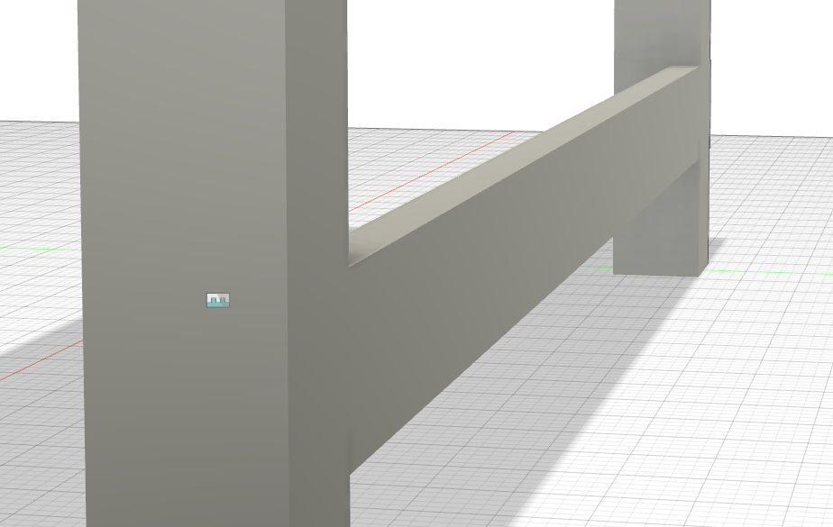
Then I mirrored the first connection so that I can have it towards the other side and joined it to the corner of the other legs.

Next, I wanted to create the inside part of my stretcher. So, I created a new sketch on the back side of my Front Stretcher:
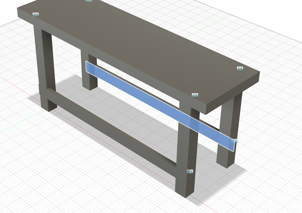
I hid everythign else so that I can primarily focus on my backside stretcher
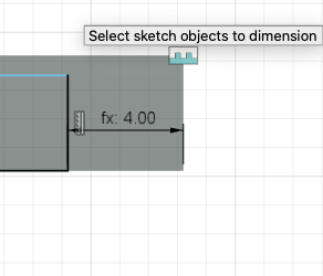
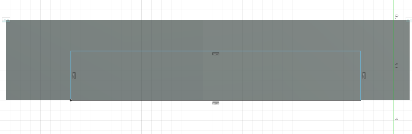
I created a free-form rectangle and will add dimensions. The first dimension I added was the leg_width on the leg side of the stretcher to the left side of my rectangle.
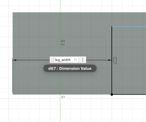
The second dimension I added the leg_width on the right side of the stretcher to the right side of my rectangle. Additionally, if you select a dimension you already created, you can reference the dimension. That is what I did to get the dimension between the right side of the stretcher to the right side of the rectangle.
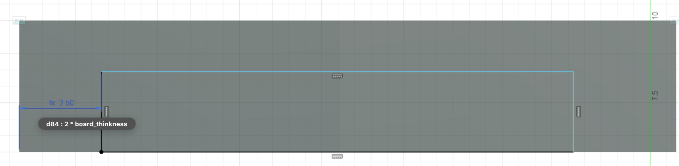
The third dimension, I needed to create a new parameter. The third dimension was the top of my rectangle to the top of the stretcher. That said, I created a new parameter called shelf_thickness which is .75 inches thick.
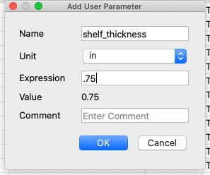
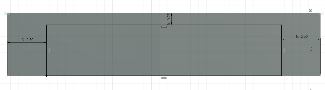
Once I created my parameter, I added the dimension to the top of my rectangle to the top of the stretcher.
Next, I extruded the rectangular face to board_thickness:
The result:
However, I am missing the inner extrusion on the other stretcher:
To fix this, I went to the timeline
I should be able to select the mirror component and move it to the right however, Fusion will not let me because of the contrainsts. So, to fix that, I selected the constaints and moved it passed the extrusion then selected the mirror and moved it passed the extrusion but before the constraints.
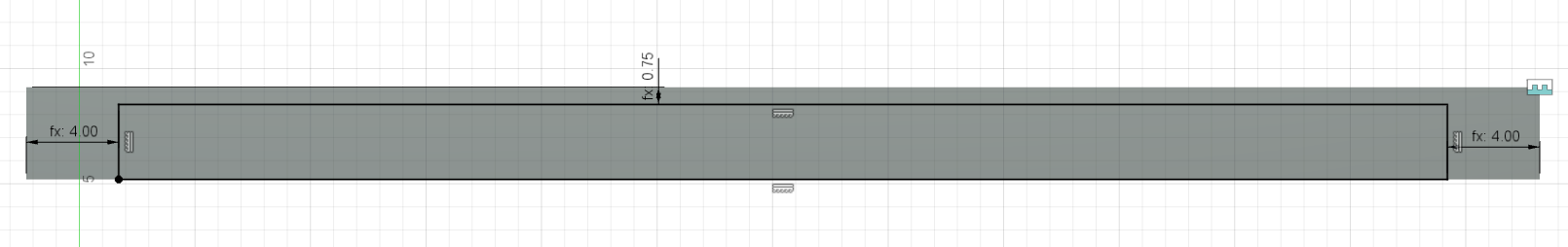
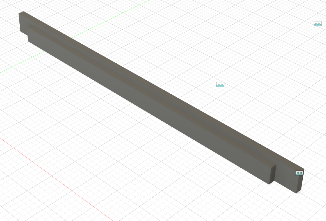
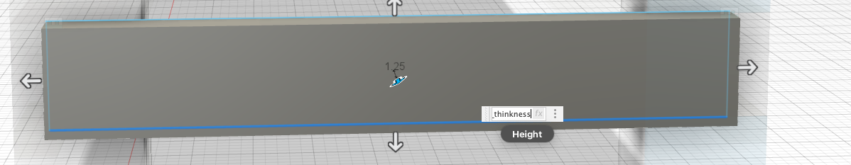
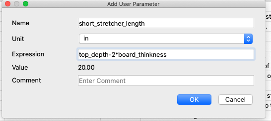
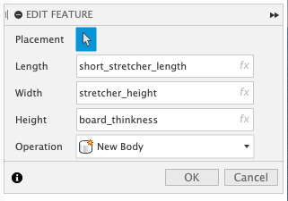
Now, to start creating the left and right stretchers. I started by creating a new component, called it Left Stretcher, created a Box for it and I clicked the outside face of the Front Left Leg and went from the corner of the lap joint up to the rear lap joint. The height is board_thickness, width is stretcher_height, and the length is top_depth - 2*board_thinkness (In order to calculate the length, I created a new component called short_stretcher_length). To continue editting the feature, I went to the timeline and selected the component.
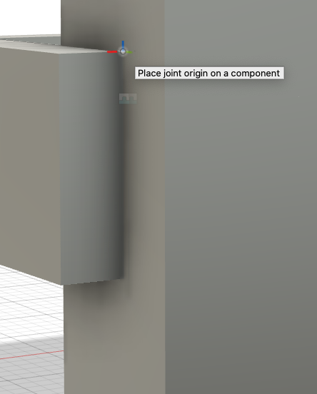
Next, to attach it to the legs by clicking j for join and selecting the back top right corner of the short stretcher and selecting the corner of the leg and a 0 offset:


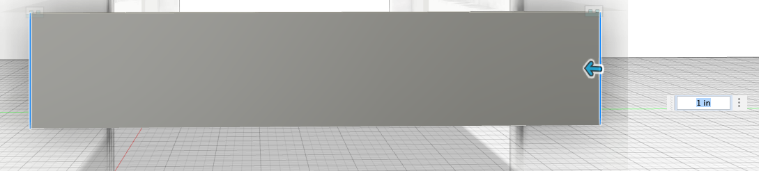
Just for looks, I chamfer the outside edges by going to the Modify menu > Chamfer**
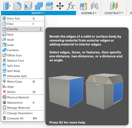
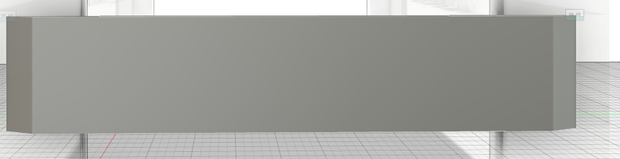
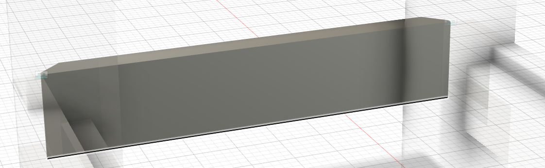
Then I click on both edges on the short left stretcher and did a 1in chamfer:
Now to create the inner stretcher on the back of shoft left stretcher. I beging by orbiting to the back of the stretcher:
I right click on the back of the stretcher and create a new sketch:
After hiding all my components for better visibility, I created a rectangle from the bottom left to mid-top right of the short left stretcher.
I added dimension from the left rectangle to the left stretcher. The dimension was 2*board_thickness:
I did the same thing on the right side.
Now, for the top, the dimension was the shelf_thickness:
Now, I extruded to create our inner stretcher. I extruded to board_thickness:
To create the right stretcher, I navigate to the Construct menu > Midplane:
I select the inside face of the front left leg and the inside face of the front right leg selecting
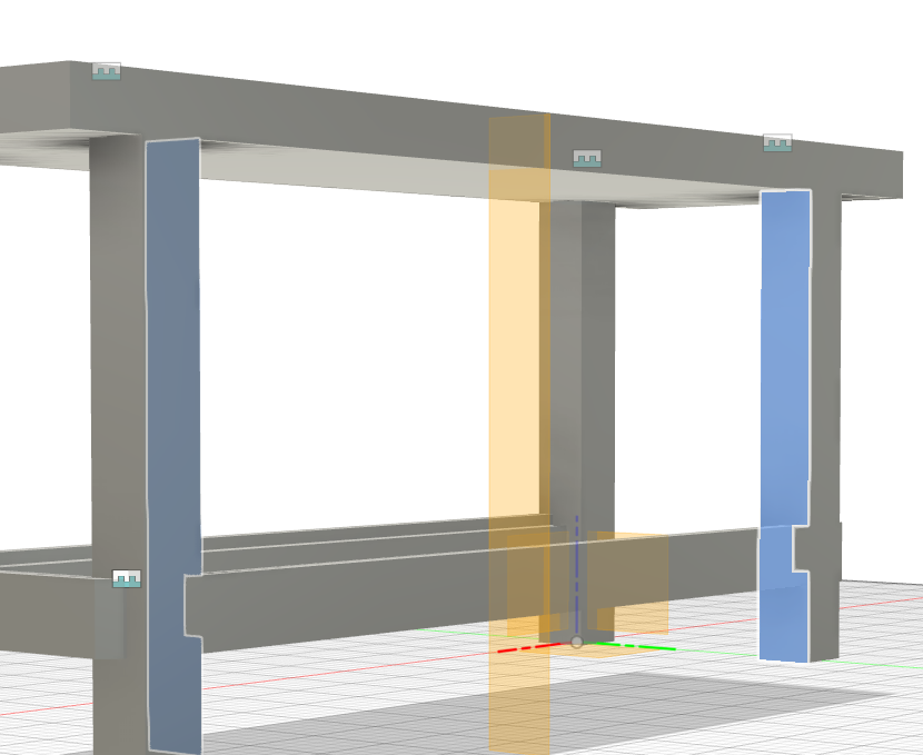
This creates a new plane which we can use to mirror the left stretcher around. I navigate to the Create toolbar and select Mirror. From there, I selected my Left Stretcher component and then selected, for the mirror plane, the midpoint plane that I just created. Finally clicked ok.
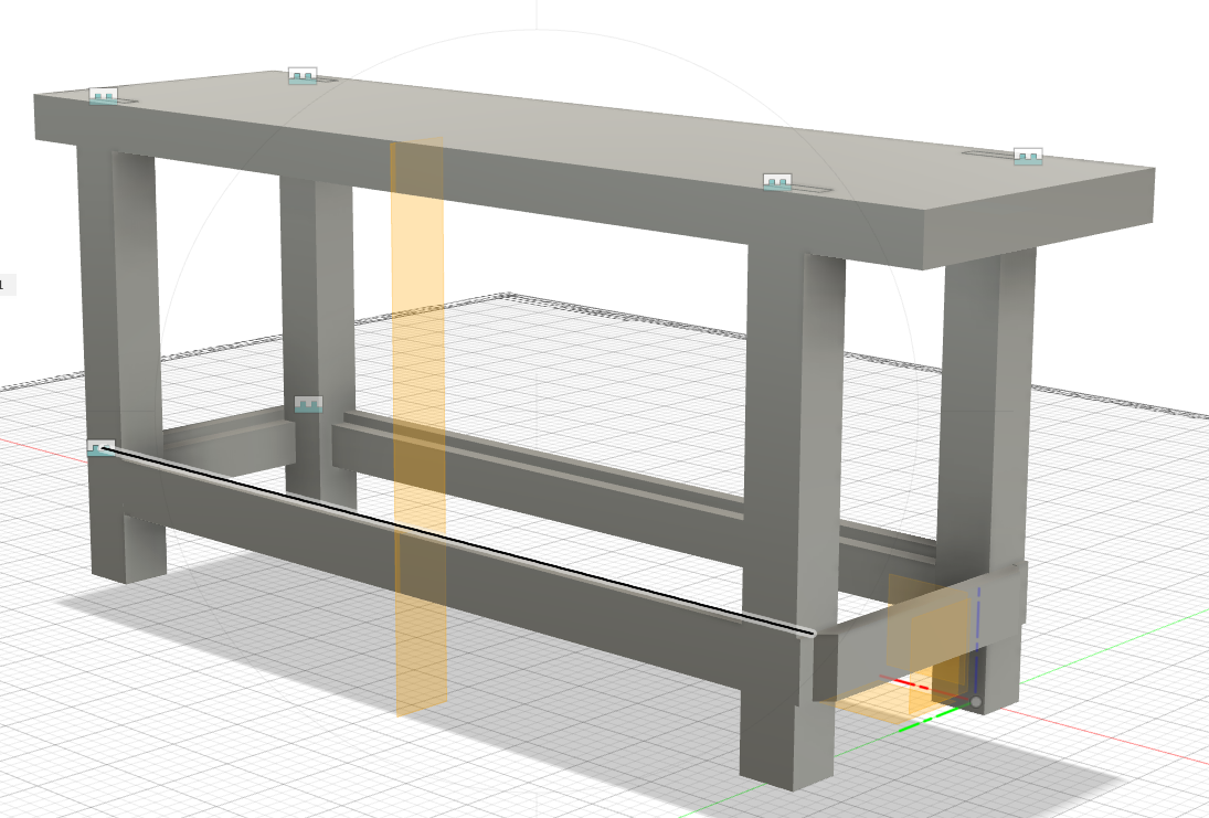
To be safe, I created a joint for the right stretcher to ensure that it’s in the correct position.
Now, to finalize it by creating another stretcher that goes inside of the legs.
I hid the construction plane to help with visiblity. I created a new component and called the compoinent inner_left_stretcher and a new paramter called inner_short_stretcher_length with a value top_depth -22board_thinkness:
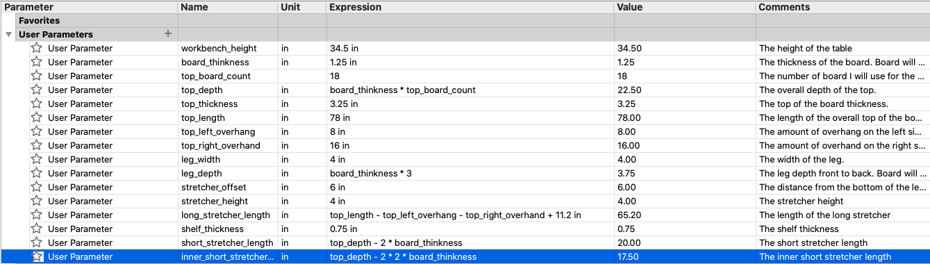
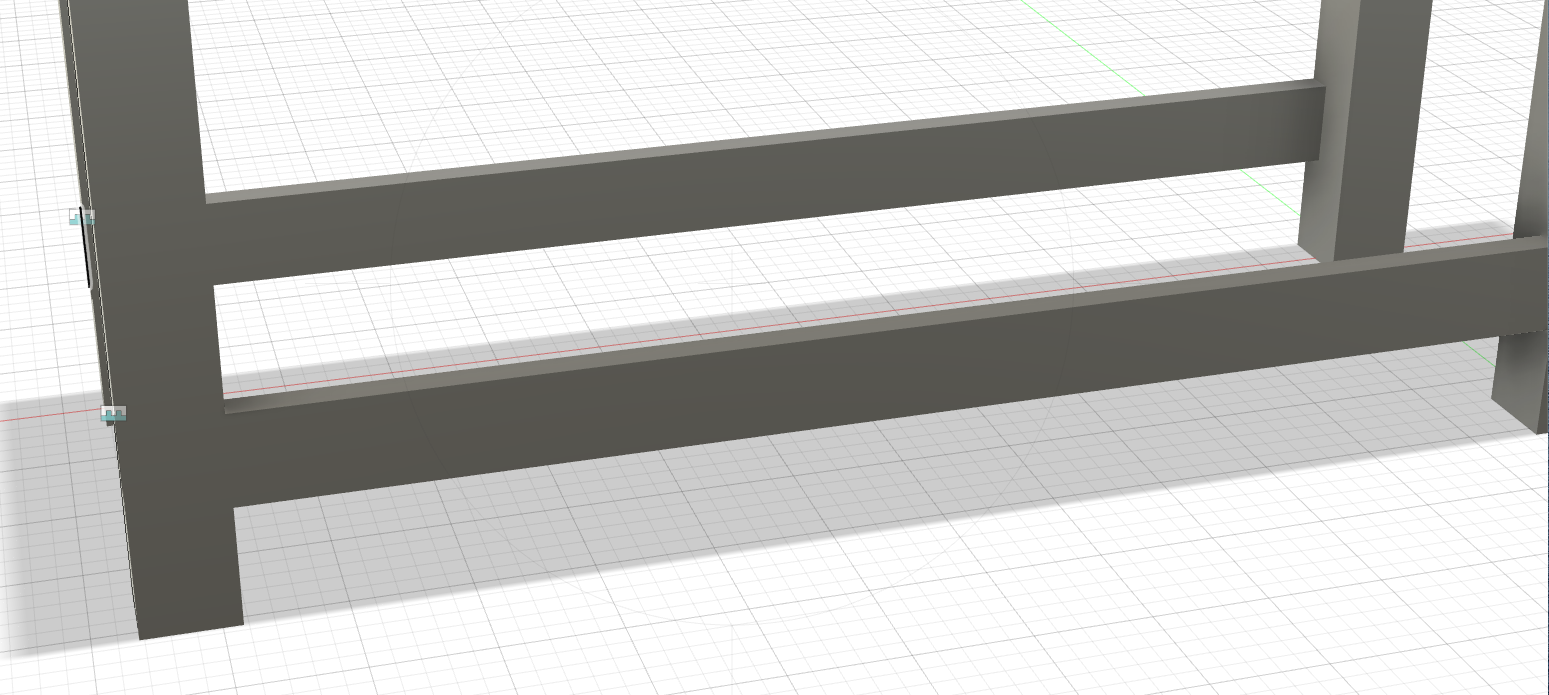
After that, I created the box for the stretcher by selecting box and selecting it’s placement to be behind the rear right leg. For now, the placement can be estimated. I extruded it to board_thickness. Now, the length of the inner stretcher will be inner_short_stretcher_length and the width will be stretcher_height - shelf_thickness. I then attached the new stretcher by joining one point to another point.
From there, I mirrored it so it can show on the right side.
Now, to add shelf which will finish my design.
I created a new sketch on the top of the inner stretcher.
From there, I drew some lines around the perimeter.
I extruded the shelf to be the shelf_thickness:
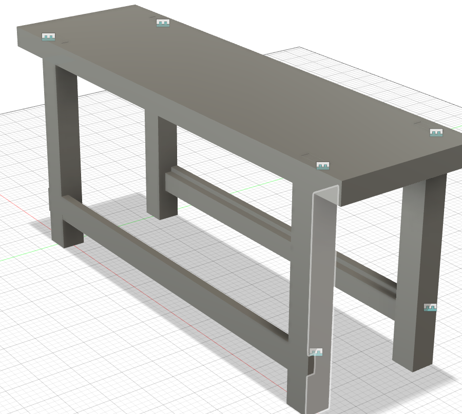
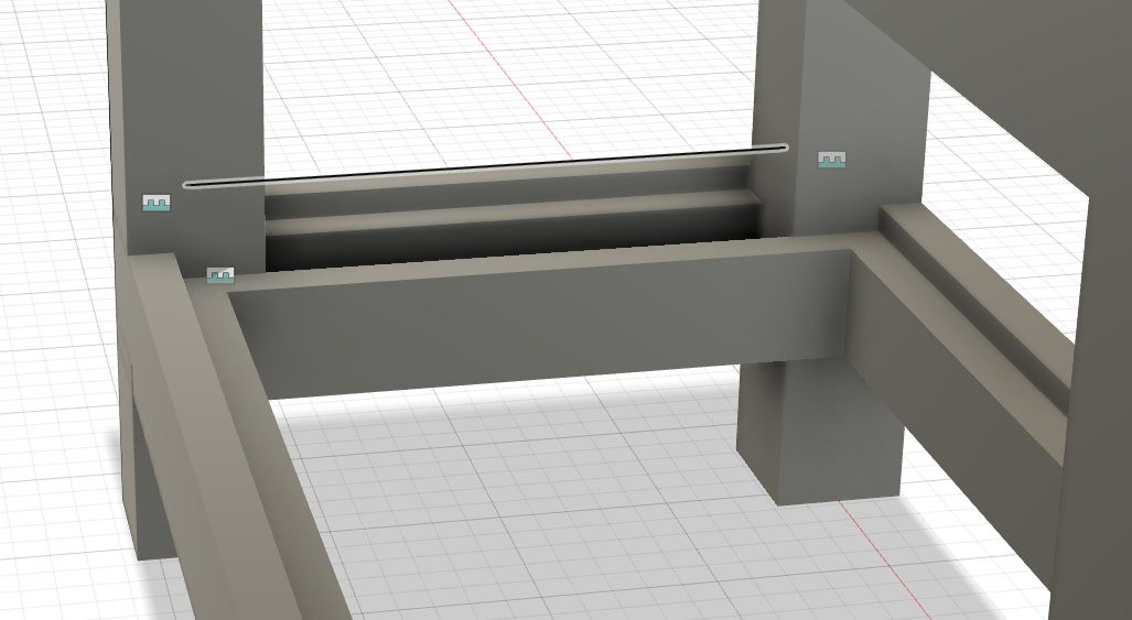
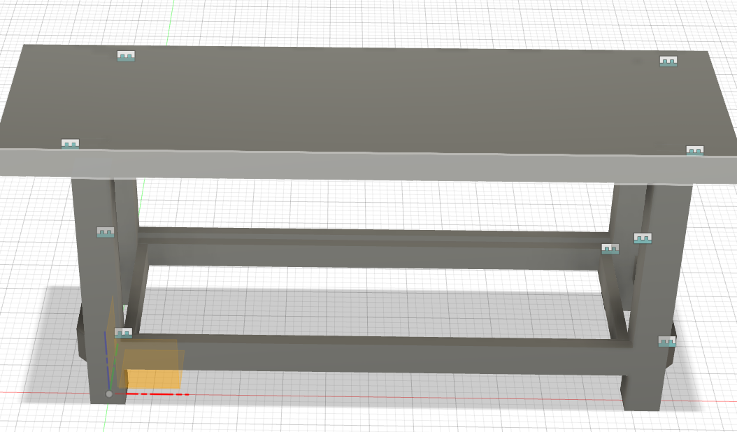
Now, the final design:
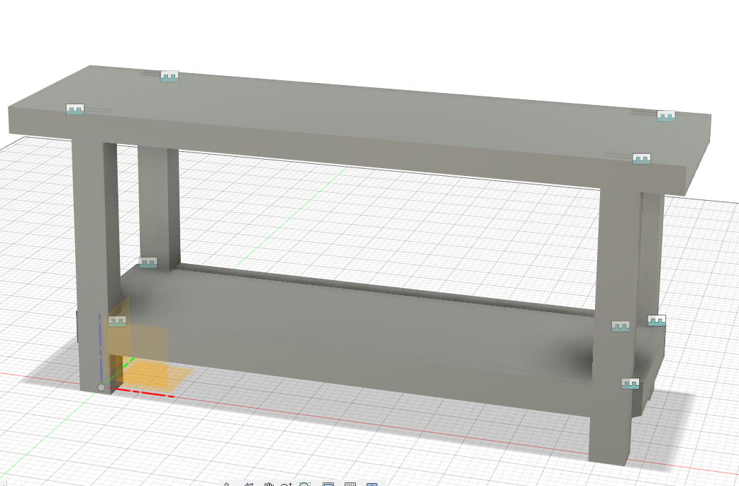
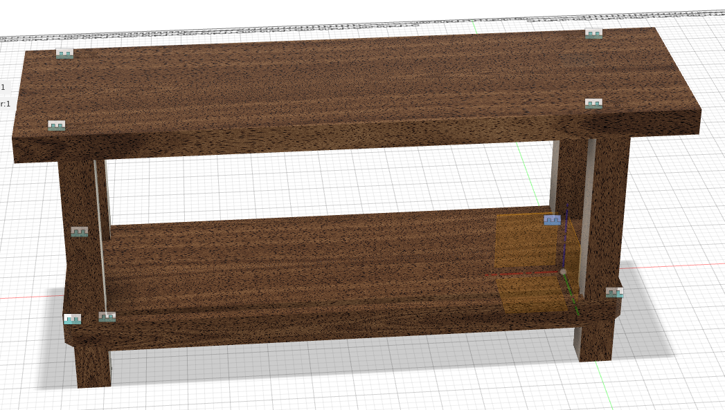
With the help of Spencer Mewherter, we were able to inspect my design and even though it was good, it needed to be worked on as the mills were unable to cut the woods in a way to make the design a reality. That being said, Spencer recommended I look at Open Desk for inspiration.
Designing Modular Shelf on Fusion 360
While looking through the sites, I found two items that I would like to create some version of it:
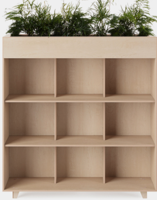
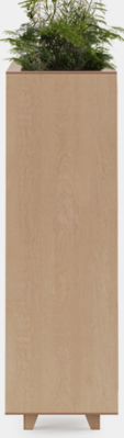
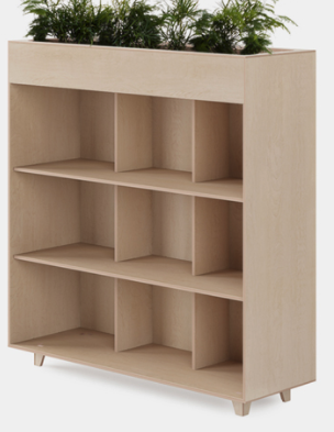
I decided to focus on the Fin Bookshelf Planter.
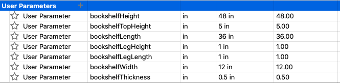
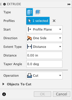
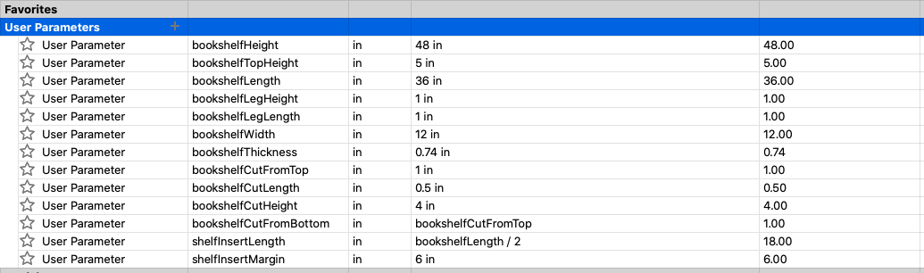
I started of creating parameters that I think I’ll need.
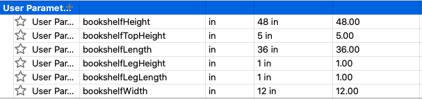
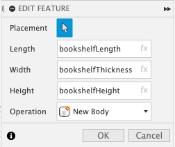
After starting a new sketch and selecting a cube, I updated the paramater as I forgot to add thickness.
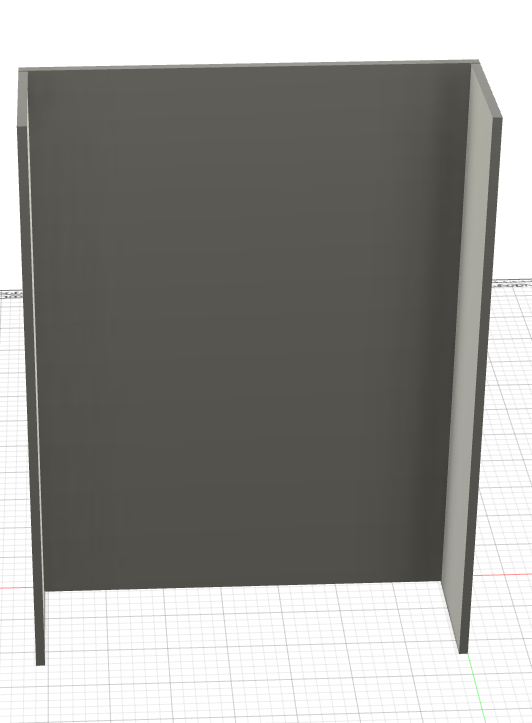
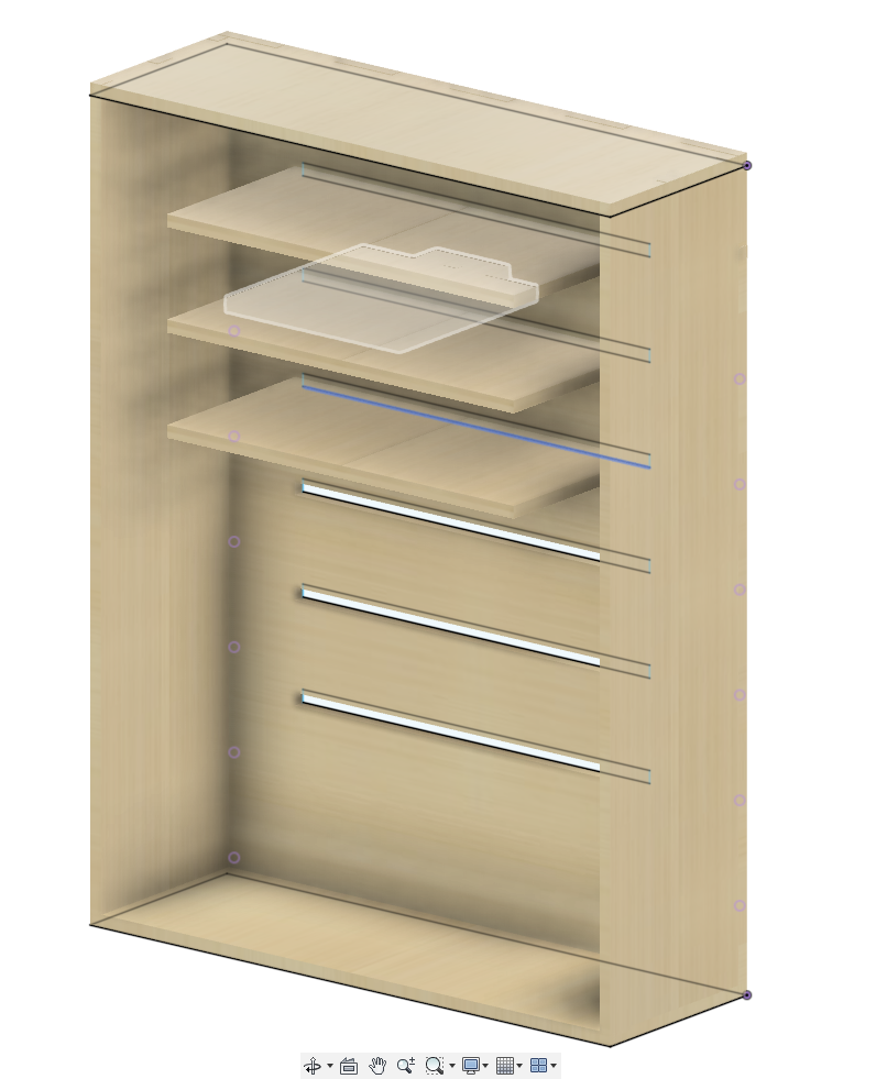
Once I did the update, I created a sketch that will allow for the insert of the box. I added extrusion and the outcome came to be:


In the above design, the features were:d
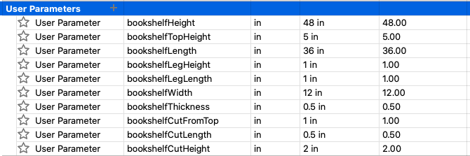
The next step is to add some cuts. To do that, I added some more paramaters:
Once I did that, I was able to edit the sketch and add some rectangles on the sides of the back. After I added the rectangles, I extruded the rectangles which resulted in:

Once I did that, I was able to add the sides on both end of the back.
I then started to add finger joints to each component.
The next step was the bottom and the top. However, I ran into some issues when adding the top and bottom. The issues I ran was getting the cuts from the top and bottom. Eventually, after playing with the extrusion:
I was able to get the job done:
Next, was working on the shelves. To do so, I added two new parameter called shelfInsertLength that’s the length of the bookshelfLength/2 and shelfInsertMargin that’s 6 incher.
The result of adding the above parameters were:
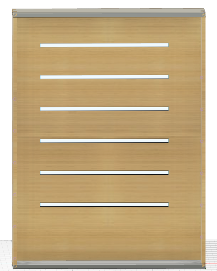
To get the above, I used the new parameters and copied the result 6 times.
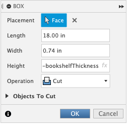
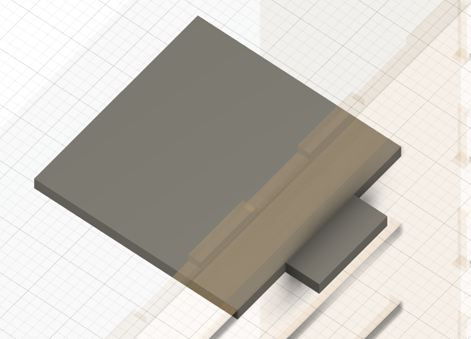
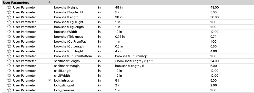
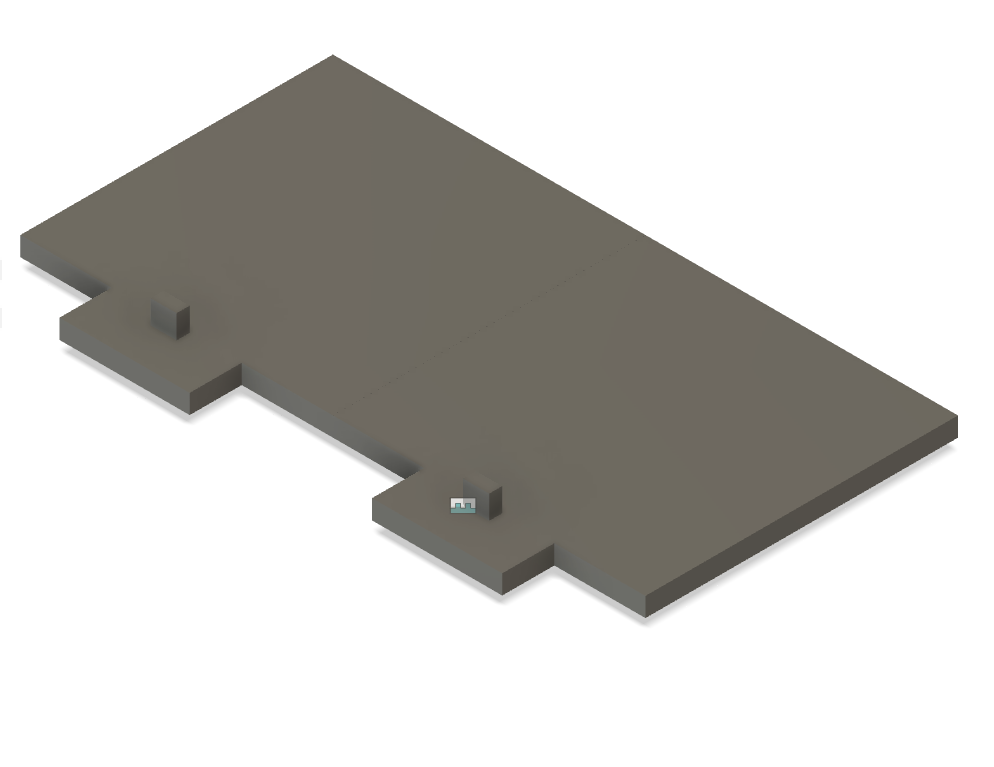
Now, for the shelves. I created 4 new parametes called shelf_length, shelf_width, lock_intrusion, lock_stick_out in order to have the shelves stick out and to insert a lock mechanism.

The result of the parameters:
Once I finished with the panel, I created a parameter call lock_measure which is 1 inch long and wide:
The result:
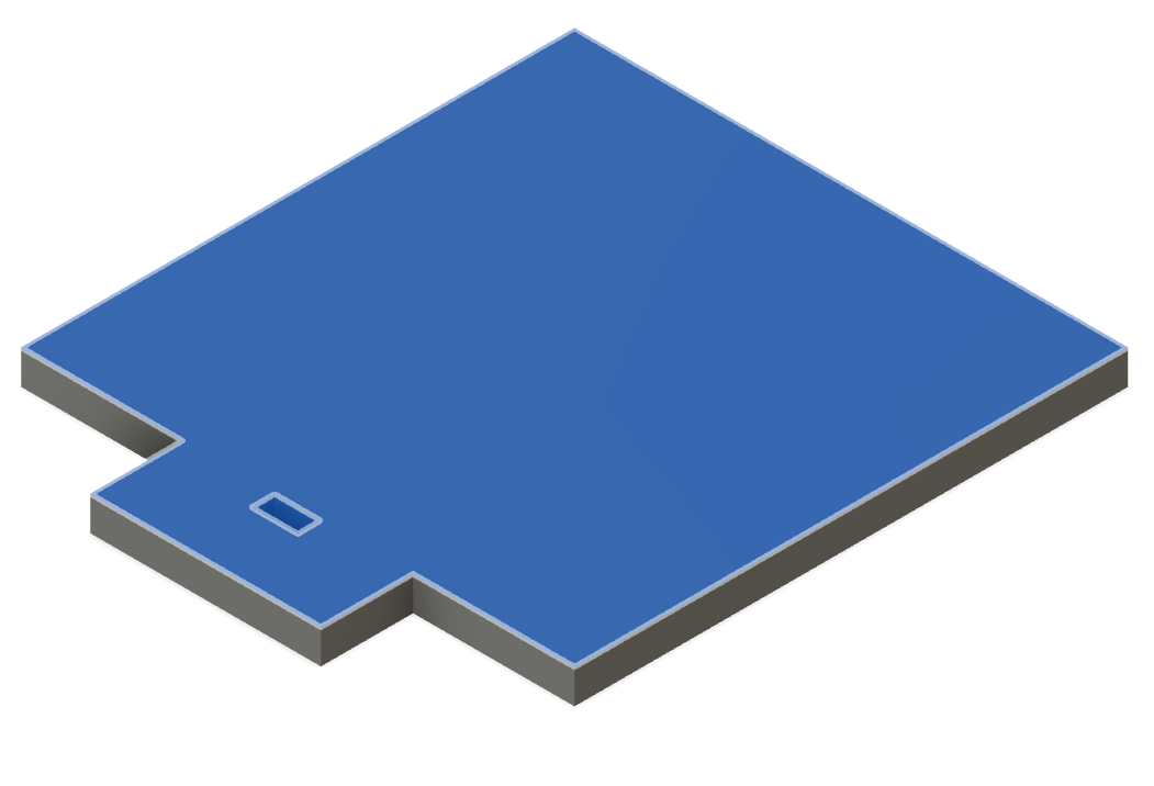
After several copying and moving, the final result came to be:
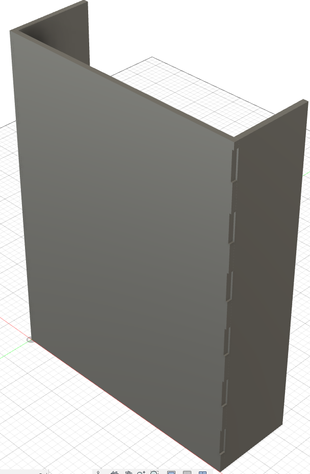
Milling & Assembling The Modular Shelf
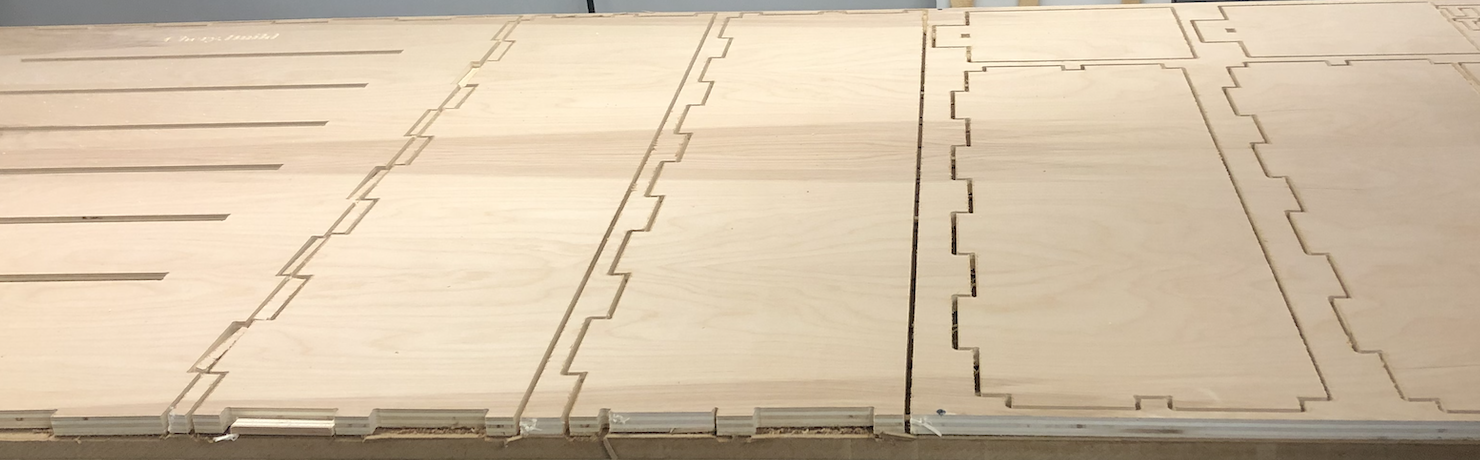
Once I finshed with my final design, it was time to bring it to the ShopBot. After several hours of working with the ShotBot, I was able to turn my design into funiture. Using the ShopBot, I milled my cuts after created a toolpath on VCarve to mill on the ShopBot. Creating a toolpath took approximately an hour or less. Once the toolpath was created, my project was ready to be cut.
I added some unique features to my cut such as:
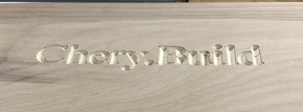
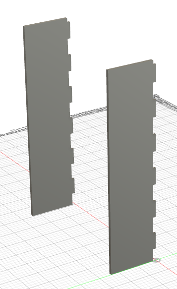
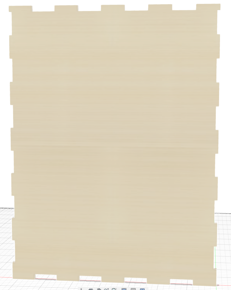
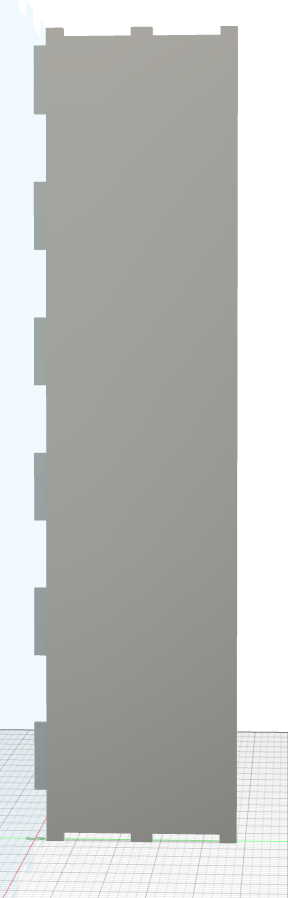
The result of the cut can be viewed below:
Now, assembling my modular shelf was simple. After sanding the pieces, I was able to put it together.
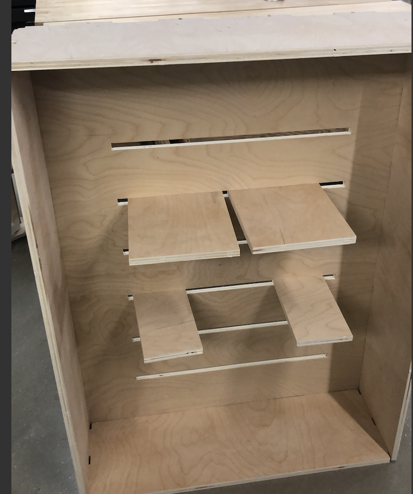
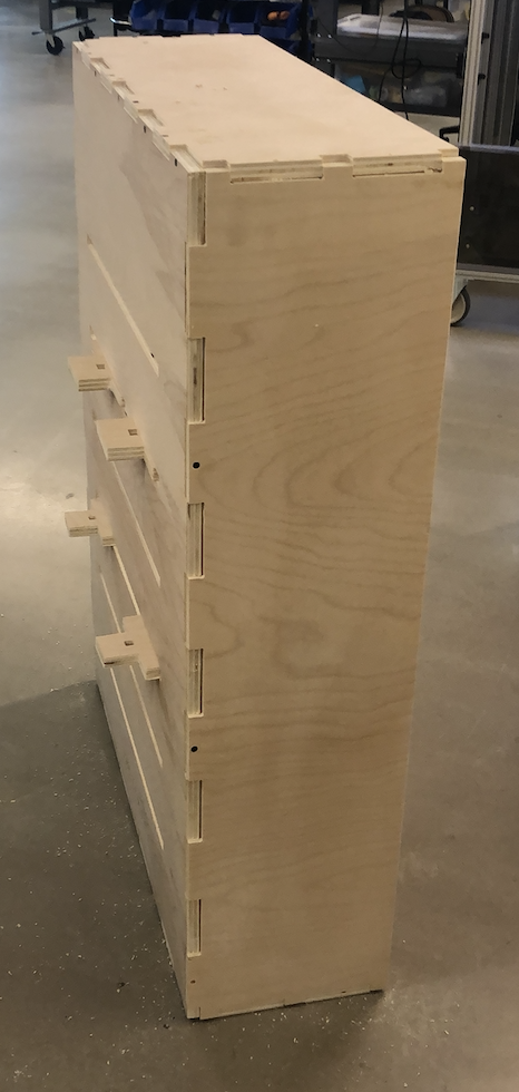
I needed to screw in some sides as some of the pieces wouldn’t stick together. But, once the sides were screwed, the modular shelf was more sturdy for items.
Here is the design files for the modular shelf: Download .f3d
Link to Group Assignment
This week group assignment was to use the test runout, alignment, speeds, feeds, and toolpaths for the machine and to document the work. Group’s Page