14. Networking & Communications
This week I began the consolidation of my prior made systems through wired networking. I worked further on the completion of my final project electronics system through this networking, and also finished up the networking aspect of my project LCD interface started last week. (Apr 28)
12-15 minutes
LCD Input Layout
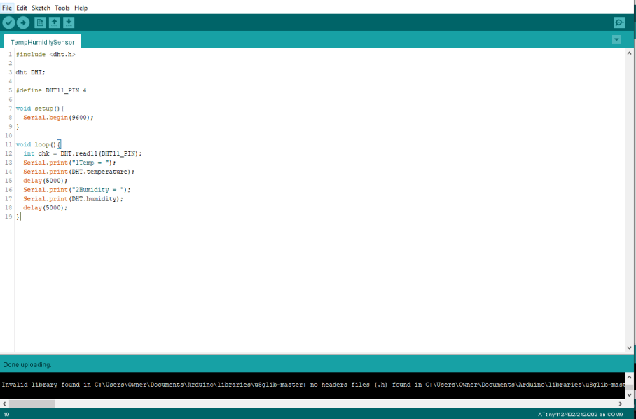
My goal for this week’s system integration fell into two steps, the networking & communication between my temperature & humidity input board and my mainboard LCD system, and the interfacing of these readings to my systems LCD screen. When I created my Temp/Humidity monitoring input bord in my week 11 class, I configured the board’s microcontroller to read the boards DHT11 temp/humidity sensor every 5 seconds and write its found values to serial. This prior work left me with a great starting place for this week, and I started the week with an input board that was already transmitting its temp/humidity values via serial. I planned to read these transmitted serial values on my Fish Bowl Main Board, made in my week 13 class, and print these serial values to a specific place on my LCD.
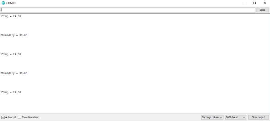
Beginning this process, I had to figure out how to print a specific line of incoming serial to a controlled position on an LCD. After a bit of research online, It seemed like the best way about doing this would be to include an indicator between different lines being sent over serial, and then read that indicator to determine the position of the text in the interface. With this idea in mind, I altered my week 11 input board’s code to include a 1 before the transmitted temperature line, and a 2 before the transmitted humidity.
This code alteration gives each of the transmitted values from my input board their own identity, being a “1” of “2”, and with that, I can place the values on the proper lines of the LCD interface. Moving on to my Main Board code, I began to alter and add onto my LCD interface code I wrote in my week 13 class and began by removing the place holder “Temp =” and “Humidity =” text. My interface code from the prior week gave me a really good starting place here, as the only alterations that were needed were in the void loop function of the code. I began here by reading the incoming serial values and writing them to a string with the code…
String IN;
String readString;

 Serial.listen();

 delay(100);

while(Serial.available()) {
  delay(100);
  if (Serial.available() > 0) {
    char c = Serial.read();
    readString += c;
  }
 }
These lines of code allow for the basic communication between my system’s two nodes, where the incoming serial, when available, is read and added to a string of information. This setup as opposed to a simple line like
Serial.read();
saves all incoming serial to a string of data until data stops coming in, and this allows me to write all of this data at the same time a little later in the code. This setup also relies on timings from my input board, as the input is programmed to leave a 5-second delay between sending temperature of humidity values, giving time for this string to be filled and used before being cleared with new data.
Next up is the parsing of this incoming serial, and the reading of those number names I gave the temperature and humidity values I set up previously. This subsystem of the function starts with setting the previously filled readString equal to the variable IN with the lines …
IN = readString;
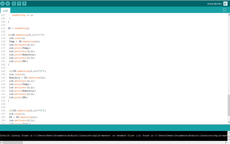
This variable is called on in an array of if statements, reading the first character in the saved serial string, and comparing it to a set 1, 2, or 3. This is the key feature that parses those number names set up earlier. In each of these if * statements the number in the first position of the incoming serial string is matched to its corresponding input, in the case of the if statement below, it is matching 1* to a temperature input.
 if(IN.substring(0,1)=="1"){
  lcd.clear();
  Temp = IN.substring(1);
  lcd.setCursor(3,1);
  lcd.print(Temp);
  lcd.setCursor(3,2);
  lcd.print(Humidity);
  lcd.setCursor(3,3);
  lcd.print(PH);
 }
Base on the number in the first position in the input string, the incoming input string is set to equal a different variable, and then this variable is printed to a specific place on the LCD, using a
lcd.setCursor(0,0);
command. Depending on what variable the input string is set to, the incoming string value will be printed to different places on the LCD.
I began testing this parsing system in a little test sketch, only including the needed pieces to read incoming serial and print it to an LCD. In the video below I send in text through the serial monitor, with a 1, 2, or 3 first character to position this text on my LCD.
With this working on the first attempt, I reintroduces the rest of my LCD interface and performed the same test on my LCD, leaving me with the ability to print serial to specific lines of my LCD interface, shown below.
Arduino Testing
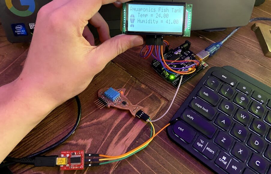
With all of this code flattened out, and implemented in the LCD interface, I was ready to move on testing the system with my temperature & humidity input board. I flashed an Arduino with the mainboard code written previously and wired the Arduino to my LCD breakout board. I next attached the transmitting serial pin of my input board to the Arduinos receiving pin and booted up the whole system. I was a little worried at first after this first bootup, as for about 5 seconds just the interface I had sorted out in week 13 was displaying, with no serial values, however after about 5 seconds the first temperature value popped up, and a short 5 seconds after the humidity did as well. This timing ties back into the time required to write the received serial data to a string and then run it through the positing if statements, so there is around a 5 second lag between updates of the values. Fortunately enough, this lag doesn’t cause any issues, as second by second accuracy in monitoring temperature and humidity is trivial in my case.
Complete System on Fish Bowl Main Board
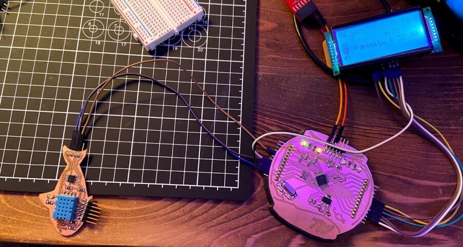
After completing this working communication system with an Arduino, I wired up an Arduino with the Arduino as ISP sketch flashed to it, to my Fish Bowl mainboard, and uploaded the working mainboard communication code.
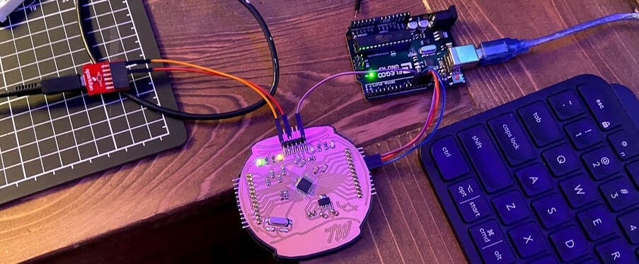
Then, just like during my testing on an Arduino, I wired my Fish Bowl main board to my LCD breakout board, and also connected the temperature and humidity input boards transmitting pin to my Fishbowl main board’s receiving pin, and booted the system up. The whole system operated just like the Arduino test before it. :)
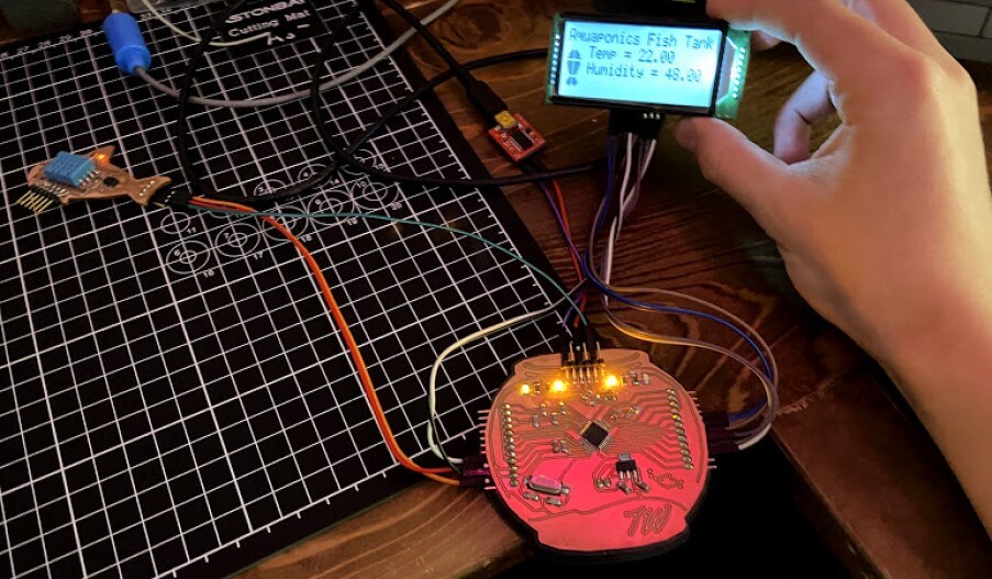
I gave this system a little test by blowing on my input board’s DHT11 sensor, increasing its humidity. This test is shown in the video, where the Humidity value on the LCD increases after I blow on the DHT11 sensor. This video also shows the approximate lag time between reading and the display of that read value on my LCD.
Software Serial - Potential for Multiple Input Nodes
Although my prior work communicating between my temperature and humidity reading input board and my fishbowl board worked great, this system is only two individual nodes communicating back and forth and leaves no room for an expanded network. After all, this week’s assignment states to “design, build, and connect wired or wireless node(s) with network or bus addresses”, implying a plural amount of addresses, thus implying a plural amount of nodes. Conveniently enough, I aim to not only monitor the temperature and humidity of my final project, but also the waters PH level, and this PH measuring input will require another node in my system. Branching off of my work earlier this week, I began to alter my code to work with the software serial library. This library allows serial communications on any of a microcontroller’s digital pins, and allows me to configure two receiving and transmitting pins on my mainboard node, and communicate with bus address to my two input nodes.
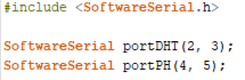
The first alterations to be made while implementing two-port communication in software serial are addressing the two communication ports and labeling their bus addresses. Using a function from the library, I set up two communication ports in my mainboard code, one for communication with my systems temperature and humidity input node, and another for a future PH input node. Through this setup, I’m able to communicate across all three nodes, passing through these two set communication ports, and will be able to call on specific nodes with their defined addresses, portDHT and portPH.
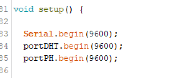
Following this port address setup, I begin serial for both of these ports at a 9600 baudrate, that used on my existing temperature and humidity input board, and will be used on my future PH monitoring board.
I implemented both of these software serial setup bits in a version of the TwoPortRecieve Arduino sketch example, found under the Software Serial Example menu in the Arduino IDE. After the setup of both of these port addresses, I am next able to call on an individual port with the line
portDHT.listen();
A limitation of the Software Serial library is the inability to listen to multiple communication addresses at the same time, so an address must be called on to listen to by a receiving board before making use of the port. Similarly to the code I used earlier while reading from serial after a port address is selected, any data from that port will be written to hardware serial until no more data is available with the lines
  while ((portDHT.available() > 0)) {
    Serial.write(portDHT.read());
  }
This same port address selecting and reading process is repeated for the second port, in my case portPH and left me with the complete altered TwoPortRecieve sketch shown below.
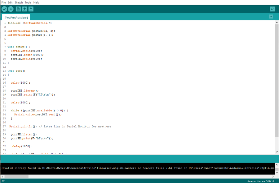
As a test for this two-port communication sketch, I uploaded the sketch to an Arduino UNO, and then connected the transmitting line of my temperature and humidity input board to pin 2, the first set receiving a pin, and checked to values in the hardware serial monitor. This was successful, so I next moved the input transmitting line from pin 2 to pin 4, cleared the serial monitor, and waited for values to come in through this pin. This, conveniently enough, worked as well, and my 3 node communication could now listen to and print from a specific address.

Using this successful two-port receive code as a reference, I began to implement the use of these addresses into my mainboard code, first setting up the port addresses and starting their serial like before, and then moving onto their implementation in the Void Loop function of my code. The alterations here involve the port being read by my parsing If statements written previously. Before all of these statements listened to the board’s hardware serial port by default and wrote them to my LCD. Here I implemented the same
portDHT.listen();
used in my TwoPortRecieve code, to read data from my temperature and humidity input through its portDHT address, and just as before, saved this data to an incoming string. From here, the data is run through two of my code’s parsing If statements, to determine whether the board is receiving temperature or humidity data, and base of this, just as before, will print the read values to my LCD.
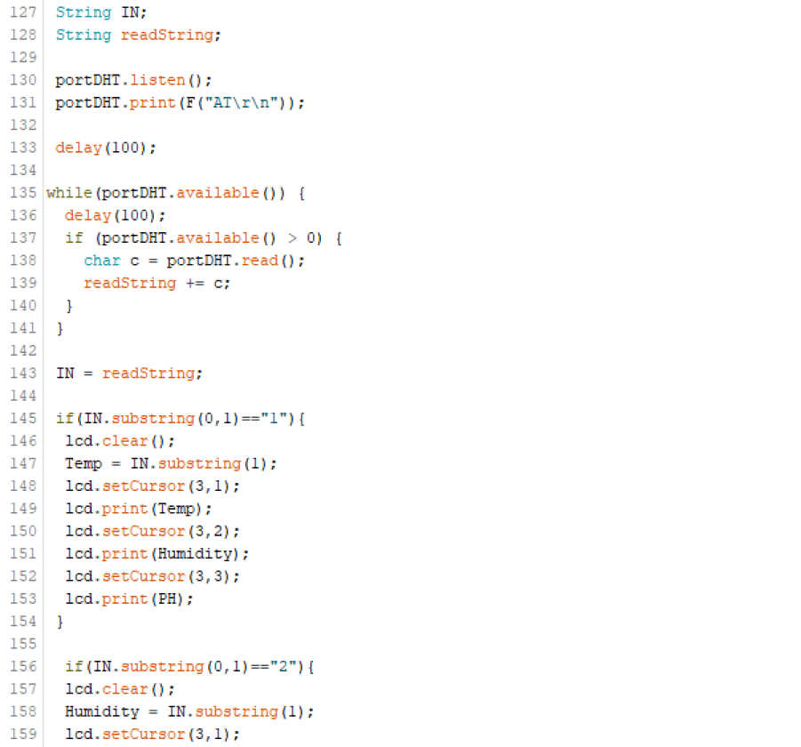
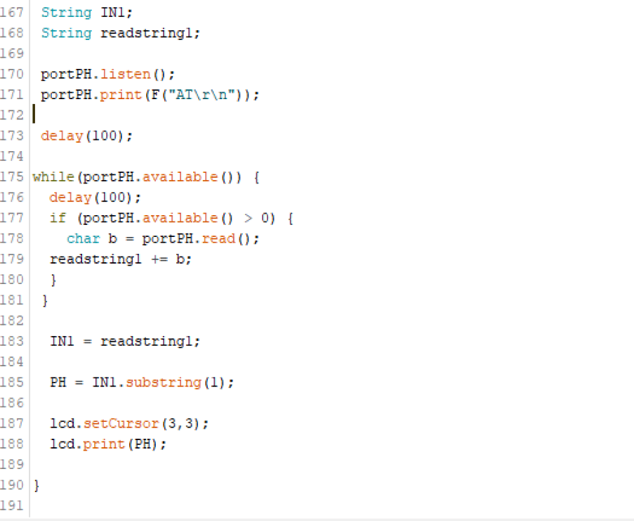
This same process is repeated in the Void Loop function, after the listing of portDHT, with portPH. This, just like the previous port, saves read data to a string, and then prints the read data to the proper line of the LCD interface, this time without any If statement due to the singular reading that will be coming in over this address.
I updated my Fish Bowl mainboard with this software serial implemented code, and repeated the same two-port test I used while testing the two port receive on an Arduino, and … It Worked! With software serial implemented in my system, my system is no longer just communication between two boards, and multiple input/output node addresses can be implemented and called upon in my mainboards code.
Group Work
This week’s group assignment was to send a message between two project boards among our group. My groupmate Drew Griggs and I communicated across our two project boards, sending messages via serial. Click here to view our group documentation site, with this week’s assignment on it.
Downloads
- Click Here to access and download all of my files from this week