8. Embedded Programming
This week I read the datasheet for the ATtiny 412 microcontroller and then used information from the sheet to program my button blink board made in week 6’s electronic design class, in as many different programming languages and environments as possible. Throughout the week I used the Arduino IDE, VSC with PlatformIO, Code Kit as environments, where I programmed my button blink board in C with Arduino Libraries, C++, Block-Based Code, and also simulated the board with Tinker Circuits. (Mar 17)
18-22 minutes
Data Sheet
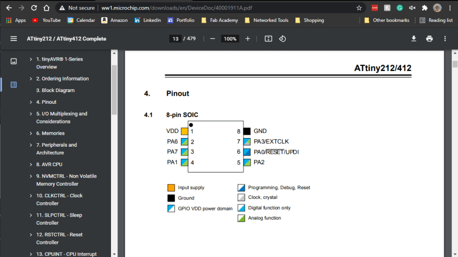
Before starting any programming of my button blink board, I skimmed through the 500-page datasheet for the Attiny 412 microcontroller. This read-through gave me useful information on the microcontroller to keep in mind while coding, such as the pinout of the chip, and peripheral registers, which came in handy while programming the chip with port manipulation in C.
Tinker Circuits
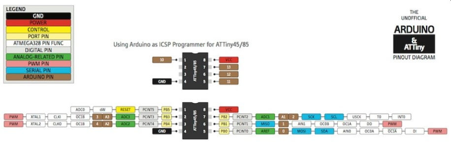
As a first step into the Embedded Programming week, after completing the datasheet reading, I used Autodesk’s Tinker Circuits to simulate a model of my board made on virtual breadboard components. I began this process by first building the circuit in the Tinker Curcits environment, basing the design on my button blinky board schematic. I attached all these parts to a breadboard and connected the circuit to a power supply. During this process, I had to keep in mind the microcontroller being used, as although my original board schematic called for an ATtiny 412 microcontroller, Tinker Circuits only has an ATtiny 45 in its inventory, and thus I had to reference a pinout (shown below) of the ATtiny 45 while creating the circuit.
With the schematic-based circuit all wired up and connected to a power supply, I used the drag block interface inside for Tinker Circuits to read the chips button pin and turn on an LED when the button was closed or switched on.
Arduino IDE
Conveniently enough, I had coded my Button Blinky board in the Arduino IDE before this week, while testing the board after manufacturing it in my week 6 assignment. During this board testing, I wrote a simple Arduino sketch that blinks a LED at the press of the board’s button, attached below.
// the setup function runs once when you press reset or power the board
void setup() {
  // initialize digital pin LED_BUILTIN as an output.
  pinMode(0, OUTPUT);
  pinMode(1, INPUT);
  digitalWrite(1, HIGH);

  }

// the loop function runs over and over again forever
void loop() {
if(digitalRead(1)==0){
  digitalWrite(0, HIGH);   // turn the LED on (HIGH is the voltage level)
  }
else{
  digitalWrite(0,LOW);
  }
 }
}
with the line
pinMode(0, OUTPUT);
setting up my boards LED as an output attached to pin zero, and the two lines
  pinMode(1, INPUT);
  digitalWrite(1, HIGH);
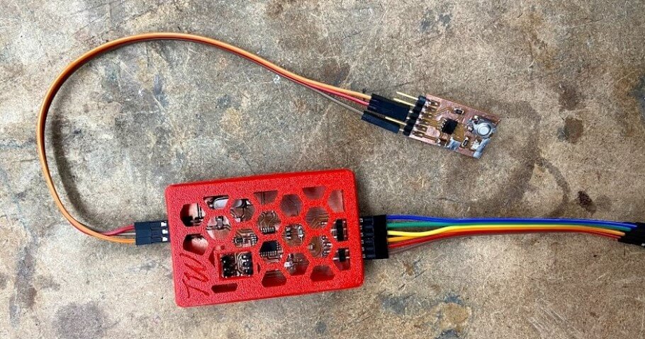
addressing pin 1 as my board’s button input pin, and activating the ATTiny 412 chips internal pull-up resistor. The process of turning on such resistor involved writing a high value to digital pin one. Due to the addressing of this pin as an input, the theory of this code is that the 412 chip will be confused by this request, and infer that that high value should run to the pin’s pull-up resistor, thus turning it on. With this code flushed out, I attached my newly made button blinky board to my UPDI in-circuit programmer I worked on in week 4’s electronics production class and then connected my programmer to my laptop through the programmers FTDI headers.
I uploaded this code from the Arduino IDE through my in-circuit programmer board to my button blinky board using the IDE’s Upload Using Programmer feature. Luckily enough, this upload worked the first time, however upon uploading the code, the LED on my board remained on at all times no matter the state of the button, unlike the intention of my code to turn the LED on when the board’s button was pressed. Originally my fear was a short somewhere on the board, connecting the button terminals. However, after some investigation under a microscope and with a multimeter testing continuity, I found no hardware issues anywhere on the board and moved onto software troubleshooting. My next guess at an error was the possibility I had addressed the boards button to the wrong pin on the ATTiny 412, but after a look back at my schematic, I found this to not be the case. I was stumped here and called on the help of one of my instructors, Dr. Adam Harris, who had me experiment to be sure the pull-up resistor connected to the button pin was activated. While doing this, I rewrote the two lines addressing the button and turning on the pull-up resistor to
  pinMode(1, OUTPUT);
  digitalWrite(1, LOW);
to measure the output pin connected to the button with a multimeter to check any resistance. Weirdly enough, however, after changing these two lines, and reuploading this code (attached below) through the programmer, my button blinky board worked as intended, turning the board’s LED on and off in correspondence with the state of the board’s button.
// the setup function runs once when you press reset or power the board
void setup() {
  // initialize digital pin LED_BUILTIN as an output.
  pinMode(0, OUTPUT);
  pinMode(1, OUTPUT);
  digitalWrite(1, LOW);

  }

// the loop function runs over and over again forever
void loop() {
if(digitalRead(1)==0){
  digitalWrite(0, HIGH);   // turn the LED on (HIGH is the voltage level)
  }
else{
  digitalWrite(0,LOW);
  }
 }
}
This success confused me due to the lack of engaging the chips pull-up resistor at all, and also the fact that I had set the button, an input component, as an output. I probed the entire board again using a multimeter in hopes of finding an answer for this success but this was to no avail. It wasn’t until I looked back through my original circuit schematic with Dr. Harris that we realized that the button on my board was attached to the VCC line over the board’s Ground. The circuit was making use of the internal resistance of the 412 chip in combination with the button being set as an output to receive button data, and flash the light. Although this attachment of the button to VCC was a flaw in my original board schematic design, the error could be worked around through software, and my blinky button board worked as intended, turning the boards LED on and off in correspondence with the state of the board’s button, as shown in the video below.
Platform IO in VSC
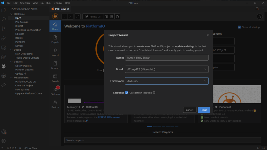
With a working button blink code running through the Arduino IDE, I began to branch off and attempted to use PlatformIO in Visual Studio Code, my code editor of choice, to program my button blink board. PlatformIO, like the Arduino IDE is an embedded development platform, that comes in the form of both its IDE software, as well as a native VSCode IDE extension. Before this week’s embedded programming class, I had installed this PlatformIO IDE in my instance of VSCode to compile Marlin firmware for my 3D printers and CNC machine, and thus I didn’t have to go through the installation process again, however, I did work through the installation process with two of my classmates, Drew Griggs and Graham Smith. Due to PlatformIO having a native VSCode extension, this installation is super easy, just navigate to the Extensions tab in the hotbar on the left side of the VSCode interface, search for PlatformIO, and click the install button. I found this article by CircuitDigest to be helpful as a reference to use while using PlatformIO. To begin the programming process, I first used PlatformIO to generate a new project for the ATtiny 412 by navigating to the PlatformIO icon in VSCode’s hotbar and then clicking the New Project button. This pops up a Project Wizard page where I named the sketch, and also selected my desired microcontroller under the Board box, selecting the ATtiny 412, then I clicked finish to generate the new project.
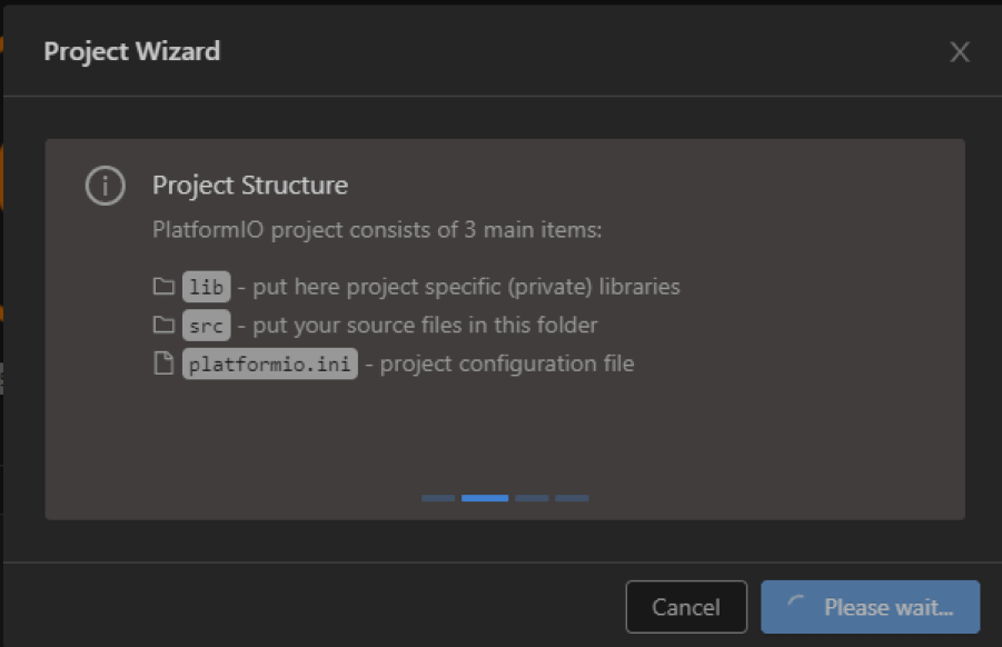
The process of project generation in the PlatformIO extension only takes about a minute or two and lays out the entire framework for PlatformIO, as well as a space for your code in the directory. As shown in the picture below, the generated director has 3 major sections, lib, a space for the sketches libraries, src, a space for the sketches source code, and platform.ini, the projects configuration file generated based on of the information put into the Project Wizard.
Keeping these 3 main sections in mind, once the project generation completed, I navigated to the src folder in the directory, where I added my Button Blink code, being sure to include the line
#include <Arduino.h>
at the top of the sketch, to ensure the Arduino native libraries would be included, allowing me to run my C code including bits from these libraries properly, making my final PlatformIO code this sketch…
#include <Arduino.h>

void setup() {
  pinMode(0, OUTPUT);
  pinMode(1, OUTPUT);
  digitalWrite(1, LOW);
  }

void loop() {
if(digitalRead(1)==0){
  digitalWrite(0, HIGH);
  }
else{
  digitalWrite(0,LOW);
  }
 }
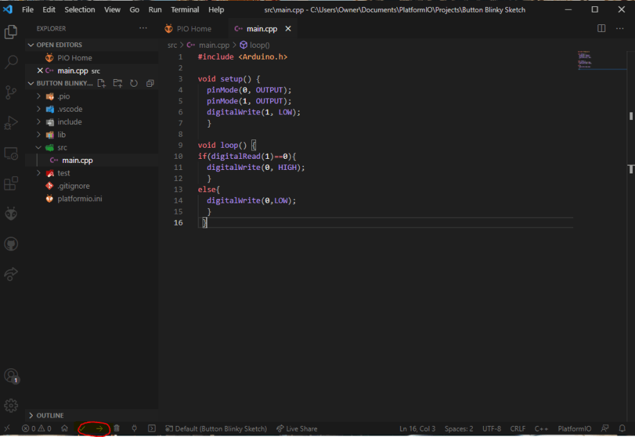
Nextly, I began the process of programming the board through PlatformIO. The PlatformIO extension makes this process incredibly easy, as the extension automatically detects the correct port, and board information, with some help off of your Project Wizard input. I hooked up my button blinky board to my in-circuit programmer, just as I had previously for the Arduino IDE testing, and connected the programmer to my computer, before building the sketch in PlatformIO. This Building process is done by clicking the checkmark icon in the PlatformIO toolbar at the bottom of the VSCode interface. The location of this checkmark is shown in the picture above, circled in red.
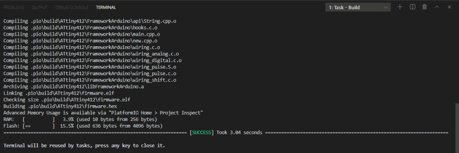
The building process opens a Task - Build terminal in VSCode, giving a verbose look at what is compiling in the building process. My code was successfully compiled in 3.04 seconds, so I was then ready to move on to upload the code to my board. In the same toolbar where the Build checkmark is found, I selected the Upload arrow, where PlatformIO opened another terminal and uploaded my compiled code to my button blinky board.
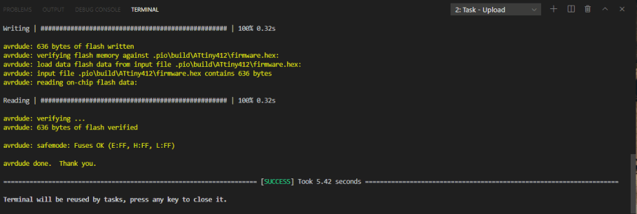
This uploading worked successfully and allowed my button board to blink. I found this PlatformIO process more enjoyable than work in the Arduino IDE, because I could run the process in VSCode, and also the potential access to a larger selection of compatible boards and libraries, and thus I ended up using PlatformIO for programming work later in this week as well.
Port Register Coding
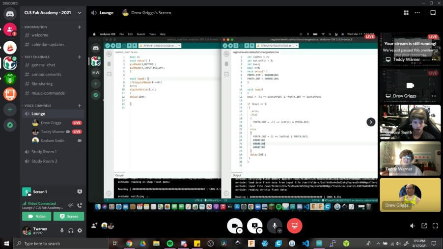
This week’s big challenge was programming my button blinky board at register level, and damn, was it confusing at first. This style of coding with port registers allows for “lower-level and faster manipulation of the i/o pins of the microcontroller”(Arduino Referance) and was a practice I attempted to use to blinky my boards led on a button press. I found the Arduino Referance site, and a page from the megaTinyCore GitHub to be helpful while trying to understand the concept of Port Regester coding, as well as two videos on Port Resisters, found here and here. Along with this prior research, I worked with two of my classmates, Drew Griggs and Graham Smith, on understanding this concept. Drew was especially helpful, explaining the process and use of bit masking to Graham and I, and also sharing his understanding of the concept in general.
Port Register Always On LED
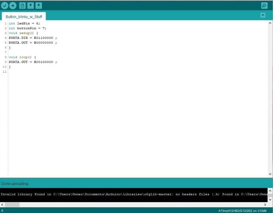
With a better understanding of the port register process, I began experimenting with the code, starting by writing a simple sketch in the Arduino IDE to turn on my button blinky boards LED. I referenced my original button blinky board code while writing this, switching outlines using Arduino libraries with this port register code. This was also the time this week where I found the ATtiny 412 datasheet the most helpful, as I used the sheet as a reference for my code throughout this port register coding process. I uploaded this code …
int ledPin = 6;
int buttonPin = 7;
void setup() {
  PORTA.DIR = B01100000 ;
  PORTA.OUT = B00000000 ;
}

void loop() {
  PORTA.OUT = B00100000 ;
}
to my button blinky board through the Arduino IDE, and was able to successfully turn on the board’s LED.

Port Register Blinking LED
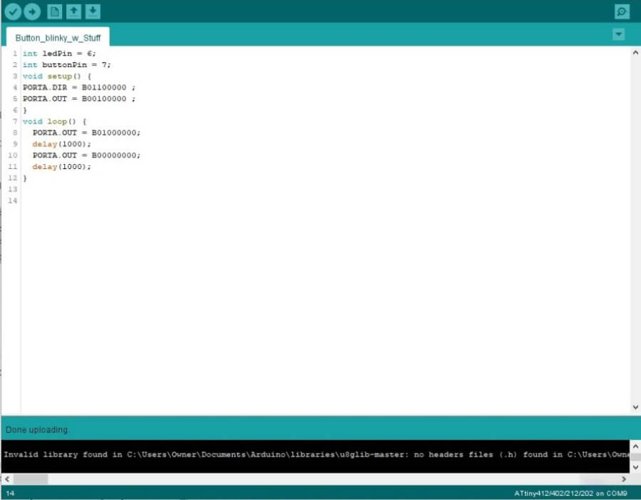
I then moved on writing a blink sketch to run on my button blinky board, altering my prior always-on LED code into …
int ledPin = 6;
int buttonPin = 7;
void setup() {
  PORTA.DIR = B01100000 ;
  PORTA.OUT = B00000000 ;
}

void loop() {
  PORTA.OUT = B01000000 ;
  delay(1000);
  PORTA.OUT = B00000000 ;
  delay(1000);
}
which sets the board’s LED pin to high, and then low in a loop, with a 1s delay in between the lines.
Port Register Button Controlled LED
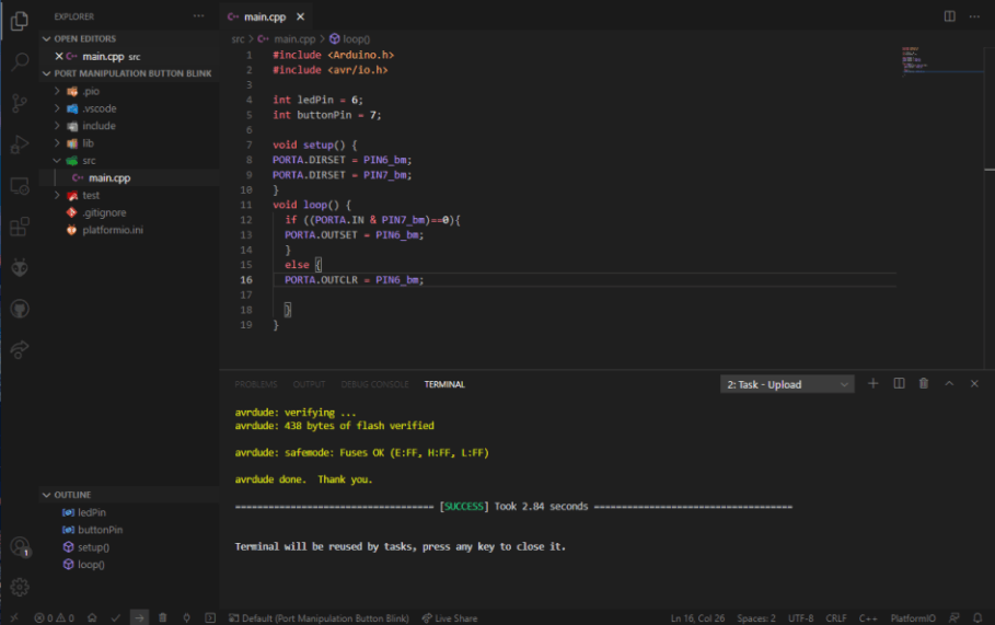
Now with a solid foundation of a port register blink sketch, I moved on to programming my button blinky board to flash the board’s LED on a button press via port register code. I ended up switching back to PlatformIO through VSCode over the Arduino IDE for this bit, but to the less harsh interface colors, and better error descriptions, so before beginning this code, I followed the same steps I took previously to create a new PlatformIO project and copied my prior port register code into the src folder in the new project. I began to find out, however, that although this prior code was a good reference, the task of coding my button blinky board to blink based on a button via port register code would be much more complex. I ended up troubleshooting this code for almost 7 hours before making progress, changing variables and different lines, until I ended up with the working code below.
#include <Arduino.h>
#include <avr/io.h>

int ledPin = 6;
int buttonPin = 7;

void setup() {
  PORTA.DIRSET = PIN6_bm;
  PORTA.DIRSET = PIN7_bm;
}

void loop() {
  if ((PORTA.IN & PIN7_bm)==0){
    PORTA.OUTSET = PIN6_bm;
  }
  else {
    PORTA.OUTCLR = PIN6_bm
  }
}
To start, this code includes two libraries, set in by the lines
#include <Arduino.h>
#include <avr/io.h>
The first of these libraries is just the standard Arduino library, allowing me to call on commands I would usually be able to in the Arduino IDE, in PlatformIO. The second library was the more interesting one, the AVR chipset I/O library. The inclusion of this library was the main breakthrough in my code, as it allows for PlatformIO to work with the I/O pins of chips in the AVR lineup, which my ATtiny 412 fell into. I used pins from this library as well as some bit masking in my final code where I had originally listed out bit values. I found that writing this code section by section helped me troubleshoot as I went along, so I did just that by switching out sections of my prior port register blink sketch with the newer code section by section until all parts worked. Overall this code is broken down into 4 sections, one setting the sketches libraries, as talked about above, the next initiating the ATtiny 412’s LED and button pins with the lines
int ledPin = 6;
int buttonPin = 7;
Despite their position in my code, these variables are never actually used once, and technically unneeded, however, I found it very helpful to leave them included to remind me of the correct pin connections of my board’s LED and button. Nextly my code includes a setup section,
void setup() {
  PORTA.DIRSET = PIN6_bm;
  PORTA.DIRSET = PIN7_bm;
}
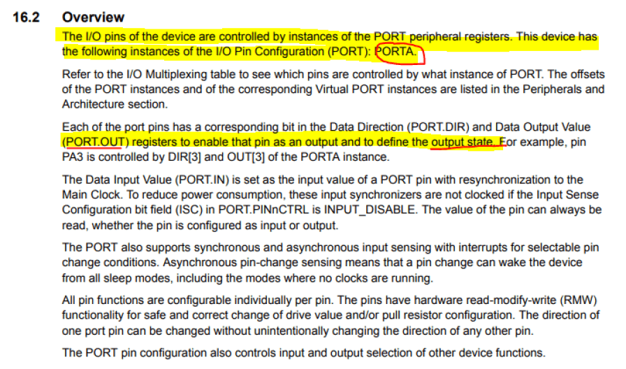
Here, In correspondence with the “PORTA” register on the ATtiny 412, I assign both the LED and Button pins on my microcontroller as outputs. The ATtiny 412 datasheet came in handy during this section, giving me the port register “PORTA” in section 16.2 (shown in the datasheet section of this page), that I used in my code. The final section of my code is the loop, the chunk of code where I wrote what I wanted to happen.
void loop() {
  if ((PORTA.IN & PIN7_bm)==0){
    PORTA.OUTSET = PIN6_bm;
  }
  else {
    PORTA.OUTCLR = PIN6_bm
  }
}
This loop starts with an if statement checking in the button pin is equivalent in voltage to that being outputted by the VCC, or “0”. If the code finds that the voltage leaving the VCC pin, and entering the button pin are equal, the code will set the board’s LED pin to its HIGH state, turning it on. If this is not the case, and there is a difference in voltage across the button, the code will address the board’s LED with its LOW state, turning it off. With code for this button blink written, I followed the same steps take previously to upload code to my board, through my in-circuit programmer, and after many failed attempts, I finally got the code running, as shown in the video below.
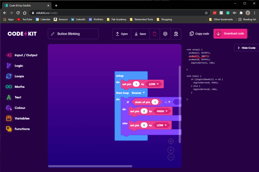
Code Kit
My final programming environment for this week is an online drag block code GUI called Code Kit. The interface is a nice simple, and colorful one, where I made my simple button blink sketch from drag block code. The code reads the state of my board’s button and then turns on the board’s LED when the button is closed. With this drag block code created in Code Kit, I downloaded the Arduino Sketch from the site using the Save button at the top of the Code Kit interface and opened the code in Arduino IDE. The code generated by Code Kit had conflicting lines assigning the button pin as an input, as well as an output, due to the odd nature of my board design talked about earlier while under the Arduino IDE section of this page. I simply deleted the conflicting line and uploaded the sketch to my board, where the board worked as desired.
Group Work
This week’s group assignment was to compare the performance and development workflows for different microcontroller families among our group. This week I worked to setup an instance of Rasbian, the OS on our used Raspberry PI, and installed Python on this Lite version of ther operating system, allowing the group to utilize the Pi’s GPIO. In addation to that, I also helped out wiring the breadboard for our Raspbery Pi Pico testing. Click here to view our group documentation site, with this week’s assignment on it.
Downloads
- Click Here to access and download all of my files from this week