5. 3D Scanning & Printing
This week I used CAD design and 3D printing to create an object that could not easily be made by a subtractive process, used 3D scanning to generate a physical object virtually, and also worked with our group to test the design rules for our labs 3d printers. (Feb 24)
20-26 minutes
3D Printing
Design
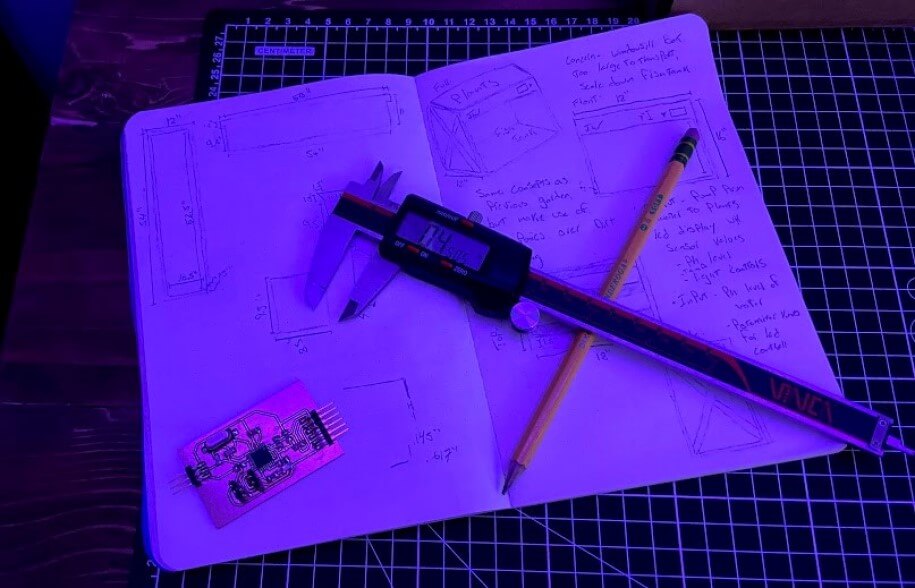
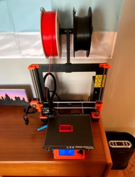
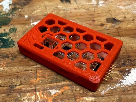
To complete this week’s 3D printing assignment I modeled a snap-fit case for my In-Circuit Programmer board I made for my Electronics Production assignment, and 3D printed the model on my Prusa I3 MK3S+. I started the process by measuring the dimensions of the board, as well as the positioning of the board’s headers, using some calipers.
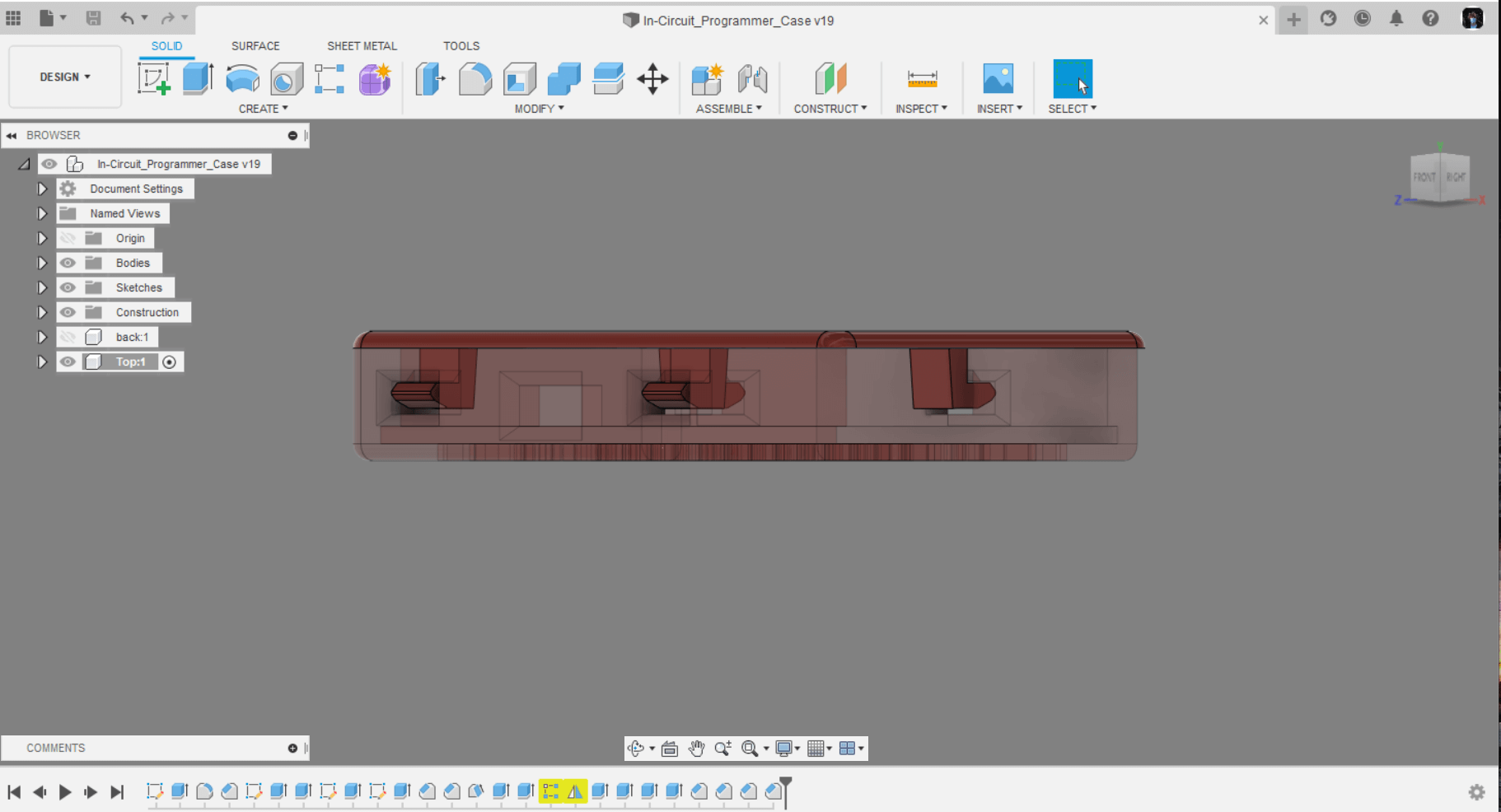
I used these dimensions, along with the programmer boards .brd file in Fusion 360 to model a case around the in-circuit programmer board. The base of the case is split into two parts, the main housing, and a back cap-like piece for the housing. The case has a lip running around the bottom inside edge allowing the programmer board to slide into the case, and then be secured by attaching the back piece to the main housing. This lip not only holds the board down but also helps align the board’s headers with the holes for the headers in the case. This lip that allows for the holding down of the board is a design feature that is easiest made using an additive manufacturing process which is why 3D printing this case is the most viable form of fabrication.
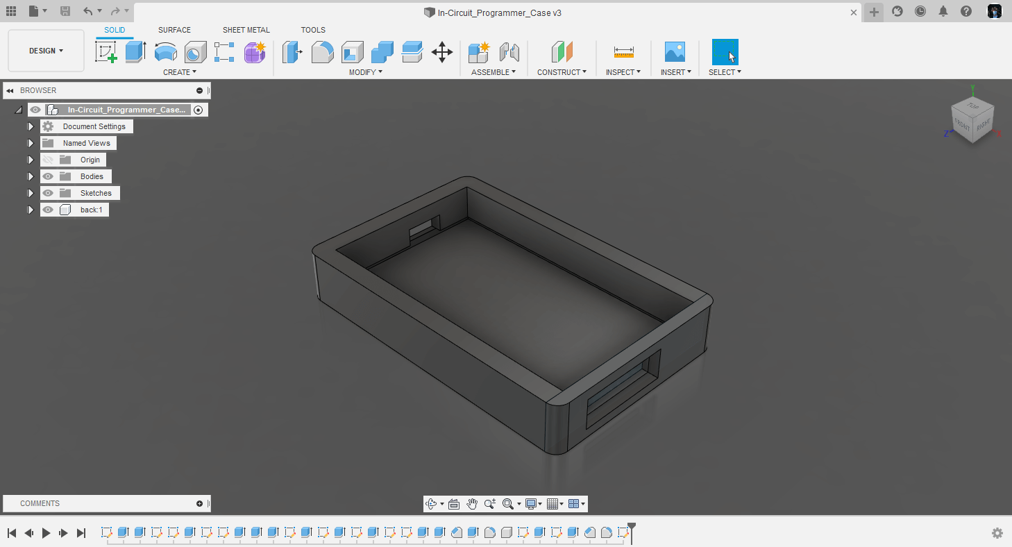
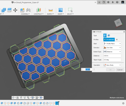
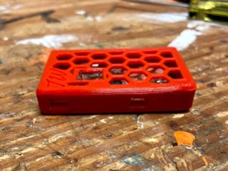
To add a little flair to my so far just plain box of a case, I cut out a honeycomb-like hexagon pattern on the bottom of the case. I used the project to surface sketch tool to make a copy of this bottom plate in a new sketch on top of the case for the lid of the case. Not only do these hexagon cutouts look pretty cool, they allow for more airflow to pass by the programmer board, no huge benefit comes from this, but I’ve found it’s good practice to allow even the smallest electronics to have airflow. While working on this projected sketch, I used some measurements take from earlier to position a cutout in the lit to allow for access to the board’s ISP pins with the lid on. I attached this cutout to the hexagon pattern, and then chamfered the top lip of the cutout so the transition from hexagon to rectangle wouldn’t be so harsh. I repeated this chamfer on all other rectangular openings on the case to keep it uniform, and also to give the pin headers some clearance. Finally, I removed some of the hexagon patterns on my lid to add in some more personalization, a TW.
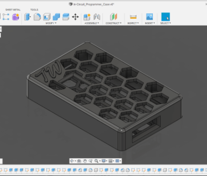
To attach the lid to my in-circuit programmer case, I settled on using four snap-fit joints between the lid and base of the case. All four of these snaps are identical, as I made use of the rectangular pattern feature in Fusion to copy one of these joints to its 3 other locations. The feature on the lid of the case has a chamfered overhang that locks into a cutout in the base of the case. These cutouts are positioned to give a 0.25mm tolerance between the top of the cutout and the top of the locking extrusion from the top piece. This tolerance holds the lid of the case securely with no wiggle, without bowing the top of the case once in place. The ends of the overhangs on the snapping pieces of the lid have a chamfer on both the top and bottom edges to assist with the alignment of the snapping bits when snapping the parts together. Leading up to this lip, the extrusion attaching the interlocking bit to the lid of the case makes use of the draft feature in Fusion, making the bottom of the extrusion, attached to the lid, thicker than the top portion attached to the interlocking bit. This angled feature allows for the snap-fit feature to be securely attached to the lid of the case, while still being flexible enough to snap into the base of the case. Finally, I also repeated the chamfer used on all other rectangular openings on the case, on the four snap-fit slots, to keep these openings uniform. I found while designing these snap-fit features, it was nice to have a reference to another snap-fit case to ensure the feature would work in the end, and this video by Kevin Kennedy from Product Design Online gave a good explanation of the workings of a snap-fit feature, and gave me some things to keep in mind while designing the feature for my case. Just like the cutouts for headers in my case, these snap-fit features would be daunting to make when not using an additive manufacturing process like 3d printing.
Slicing
After finalizing a CAD design, the next step to 3D printing is the Slicing process. I downloaded the three different components of my case design, the main base, the backing of the base, and the lid, as .stl files and imported these into Ultimaker Cura, my slicing software of choice. Cura converts your CAD work into machine-readable code and allows you to alter settings to alter your print results. My 3D printer, the Prusa I3 MK3S+, has a great community of users of their online forum, where I found the machine profile I use in my slicer. This profile was made by Prusa Research themselves for the Prusa I3 MK3S(+) models and is the profile I’ve been using for the machine since December of 2020. With this profile comes different presets for settings used of the machine, as well as some Prusa filament options. I printed my case with the MK3S_MK3_0.15_Optimal-Normal preset, printing at a 0.15mm layer height with the optimal speed setting. This is my default setting reset as it yields very high-quality prints relatively quickly, and in my opinion, is preset with the smallest compromise for speed or quality. I choose a nice red PETG filament by Duramic 3D to print my case from and selected the Prusament PETG material type in Cura accordingly. Although this material preset is meant for use with Prusament PETG filament, I find that the preset also works better than the generic PETG preset in Cura, and I usually opt to use it anytime I’m printing in PETG. I find these slicer settings and material profile to be so good for PETG, that it becomes my filament of choice over PLA. Because of this, right next to my printer is an Air Purifier I run while printing. This, along with some open windows, gives me the ventilation needed to safely print with PETG, in my opinion, a small price to pay for the better material properties, and easier postprocessing. Once my settings were selected in Cura, I sliced the model into two parts, one for the two base pieces of the case, and one for the lid. The only reason I did this was timing, as I try not to have a print run later than 10 pm when my printers in my room. With these two files, I was able to print the lid right after slicing, and the case pieces the next day. Both of these models used supports, on the base to hold up the overhang created by the lip meant to hold the in-circuit programmer board in the case, and on the lid to support the overhangs on the snap-fit features.
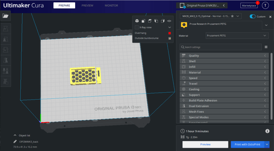
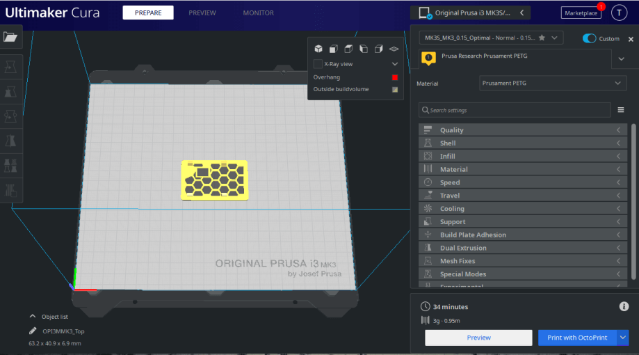
The first sliced model with the case base parts was predicted to take an hour and nine minutes to print, and the second model with the lid for the case was predicted to take 34 minutes to complete.
Printing
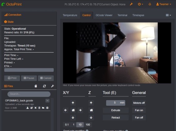
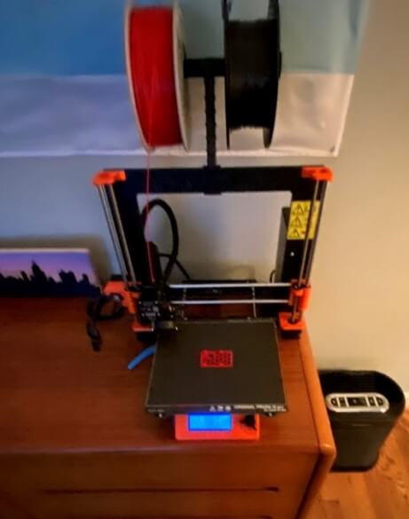
With the case parts sliced, and the gcode files ready, I was now ready to prepare my 3D printer and print my files. I run an instance of Octoprint on my printer, allowing me to control my printer through a web interface over my home network. This interface makes preparing and sending prints to my printer relatively simple. I first preheated my printer through Octoprint with a preset PETG temperature I had set up previously. Once heated, I loaded my Duramic Red PETG into my printer. The Prusa I3 MK3S+ makes this process effortless, as it uses a filament sensor to detect when the filament is put in the filament path, and will then pull the filament all the way through, and out the nozzle. A practice that I use when inserting filament is snipping the tip of the filament at a sharp angle with some cutters, before inserting it into the filament path. This angle helps guide the filament through the path and makes it harder for the filament to get stuck on anything on the way to the nozzle. After this I switched the smooth build plate on my printer’s bed to a textured build plate, the optimal surface to print PETG on. The Prusa I3 MK3S+ has a bed that attaches to build plates magnetically, allowing y=users to switch plates for different materials. Once my filament of choice was loaded, and my bed was swapped, I went back to Octoprint, dragged my gcode file generated by Cura over into the interface, and then clicked the print button. The printer then began the heating process, to reach the temperatures required by the material setting selected earlier in Cura. During this time I cleaned the bed with some 91% Iso alcohol (a process that I do every 2 to 3 prints), and also made sure the nozzle of the printer was clean by scrubbing it with a brass toothbrush, and finally, I could let the printer do its thing. My printer is equipped with an auto bed leveling sensor, so after reaching the required print temperatures, the printer auto leveled and then started my print. Besides the easy machine controls, the use of Octoprint on my machine gives me a plethora of other features. The interface comes equipped with a timelapse feature that makes use of a webcam attached to the printer itself, and I used this timelapse feature to film both of the prints for my in-circuit programmer case.
The total print time for both of these parts was just under 2 hours, and both prints came out great. Once the print finished and the printer cooled, I could remove the build plate from the printer, and take off the prints.
Postprocessing
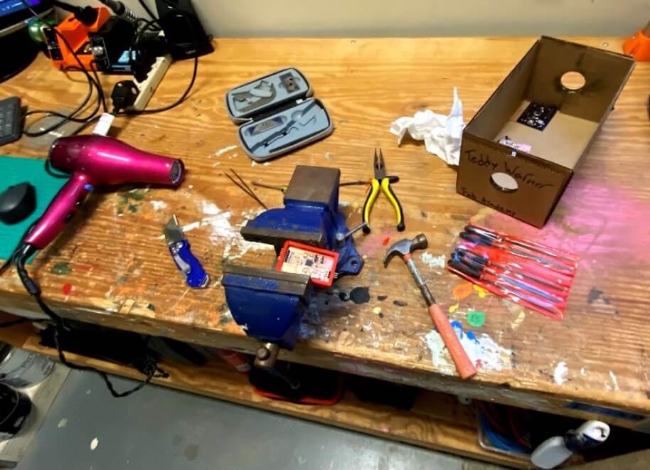
With both of the prints for my case finished, I moved on to the process of post-processing. As talked about earlier, my love for PETG stems from the ease of post-processing. Unlike PLA, PETG can be easily sanded using either sandpaper and files. On top of this, any stringing created on the model during the printing process can be easily removed with a little heat for a hairdryer, or a heat gun. I first removed all supports from both models, the bits holding up the snap-fit features, as well as the piece holding the overhang from the programmer’s slot in the case. I cleaned up all these sections with a little pack of files, some tweezers, and a tiny hammer and flathead screwdriver (to remove some stubborn support in the slot overhang). After removing all support, I heated the stringing in the hexagon pattern, removing little wisps of material, and leaving a really clean look after cleaning up some more with tweezers. Although PETG is more resistant to temperatures than PLA, little wisps of the material can easily be removed using this heating method, making cleanup easy. Once all of this was finished, I washed both parts with some soap and water to remove anything on the surface of the prints, and after drying, the case was ready to be assembled. I started by sliding the programmer board into the slot on the case, aligning the board’s headers with the correct harder cutouts on the case. Then I pushed in the base backing piece, sticking this to the main body with a little superglue, and holding the pieces together with a vice clamp just to be sure they didn’t move. The glue took around 20 minutes to dry, and after it was set, the programmer board was locked in.
Once the two parts of the case base were attached, and the programmer in its slot, I could finally snap on the case’s lid and have a full encloser. The snap fits on my case worked great, and I was able to align the top lid on the case and push down to snap the two parts together. The case works great as a protector for my in-circuit programmer board and looks pretty cool too.
3D Scanning with Photogrammetry
Meshroom
To complete this week’s 3D scanning assignment, I took advantage of Meshroom, a software that renders a mesh based on many pictures of an object, a practice called photogrammetry. I’ve experimented with Meshroom a couple of months before starting Fab Academy after watching this video about the software and the practice of photogrammetry by Prusa Research, however, I was never really able to get a successful scan. Despite my lack of luck, these experiments, along with the Prusa Research video gave me some knowledge on the workings of Meshroom, and some best practices to keep in mind while scanning an object using it.
Remington Bronze Horse Sculpture
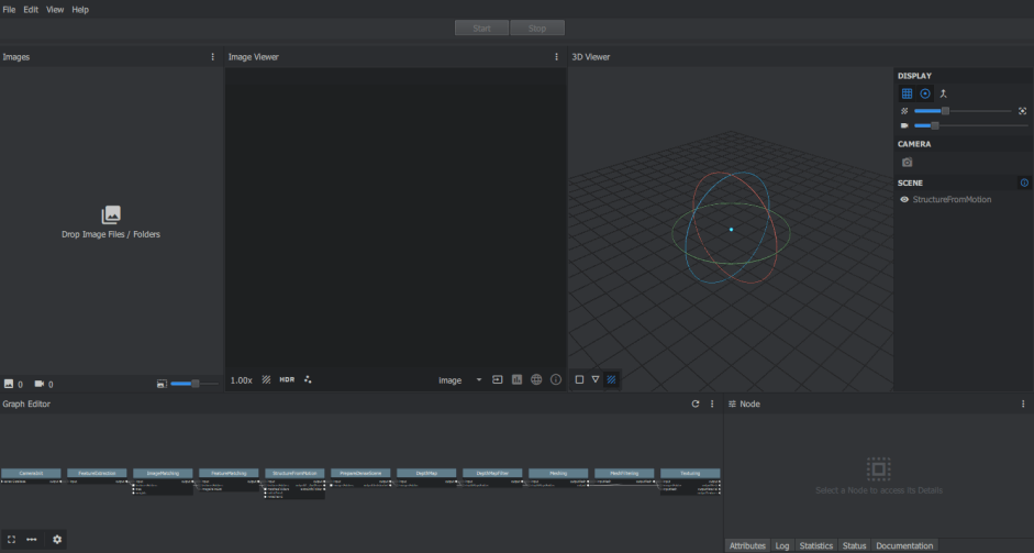
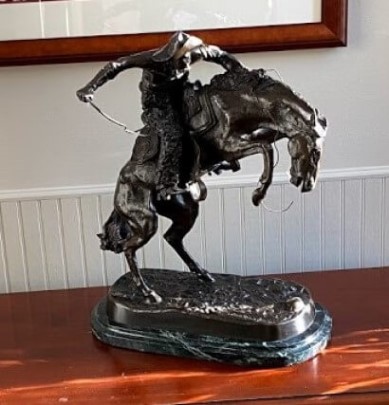
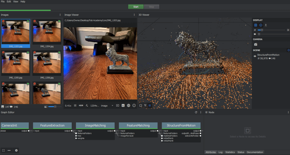
On my first attempt at scanning with Meshroom, I tried scanning a Bronze Horse Sculpture we had on a table in the entrance of our house. The first step to photogrammetry 3d scanning is to take lots of pictures of your object. As described in the Prusa Research Photogrammatry Video referenced earlier, it is best to take these pictures by going around and object in a circular pattern, varying the height of the shot and the closeness to the object in each circle. I set up the sculpture in the middle of an open area in my house and took just over 250 pictures of the sculpture in these circular patterns. Meshroom recommends a minimum of 50-100 images to generate a mesh, so this 250 was plenty. Although this process of taking images could be sped up by taking a video of the object, as said in Prusa’s video, this is not recommended as the quality of the images will not be nearly as high, and therefore the mesh may not turn out. I took all these images on my phone camera, and send them to my computer through the cloud, where I imported them into the meshroom interface. A quick note is I set up my camera to save images as .jpeg files over the .heic standard, as the .heic file format is not supported in Meshroom. The meshroom interface comes equipped with a Graph editor section, where a user can change the processes ran when rendering a mesh, and chose to start and end processes early. After importing all of my .jpeg image files by dragging them into the interface, I ran a StructureFromMotion compute. This processes all of the images to the point where the user can see a StructureFromMotion plot in Meshroom’s 3D viewer. This plot is not the full render of the object, but instead is just a map of all the camera positions where images were taken, as well as points generated from the images. Running this StructureFromMotion compute over the full rendering process is a way to be certain Meshroom is doing a good job generating points for your object and is significantly less time-consuming than a full render.
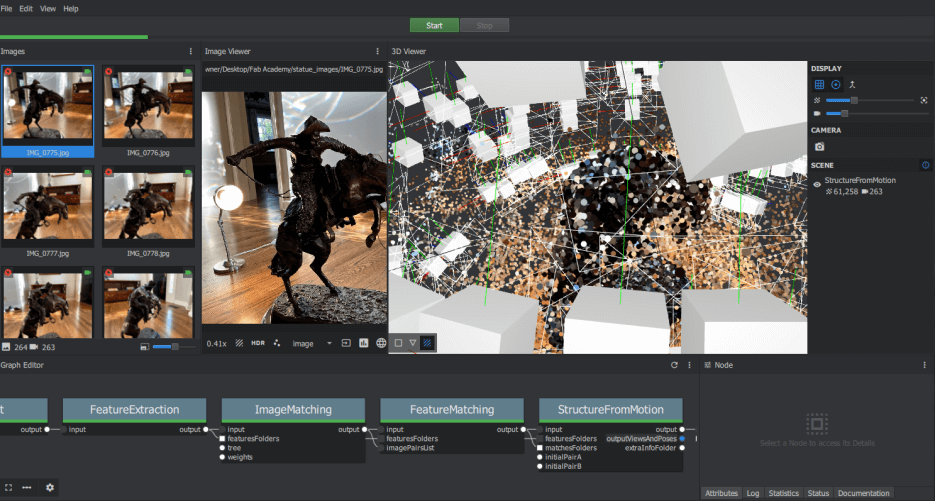
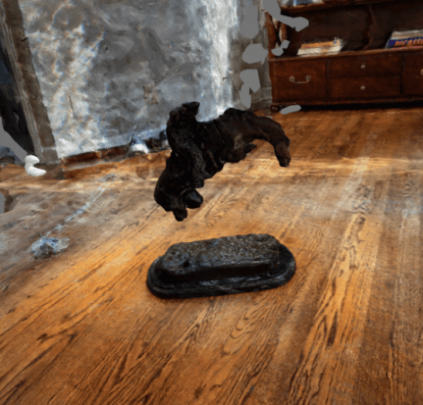
The plot generated from the StructureFromMotion compute of my horse sculpture scan looked good after review, and I continued with the object render itself, by clicking the start button at the top of the interface. This mesh took around 2 hours to render on my laptop and left me with a textured .obj file of my horse sculpture. Unfortunately, although recognizable, the mesh generation failed, and my sculpture mesh was missing the legs and the arms of the horse rider. My theory behind this failure lies in the images taken of the sculpture and the properties of the sculpture itself, as the points generated by Meshroom seemed to form a complete mesh. Although I took note of the lighting in my picture taking, I think the bronze material the sculpture was made out of reflected too much light in too many different ways throughout the picture taking process, and therefore Meshroom couldn’t generate a proper mesh of the sculpture.
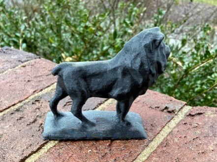
Chicago Art Museum Lion

After my fruitless attempts at scanning the bronze horse sculpture, I gave the object I wanted to scan some more thought. I settled on a bookrest modeled after one of the lions in front of Chicago’s art museum, as the size of the bookrest was great, and the whole object was coated in a non-reflective paint. I followed the same steps I used to take and process images of the horse sculpture for this lion bookrest, however, during the picture taking process I took extra caution to ensure constant lighting. Apple’s night mode helped me with this, as once I set in the night mode settings, each image of the lion would have the same lighting. Despite its help, this night mode tool also slowed me down quite a bit as when in use there is a 6-7 second processing time after each image was taken, which added up quickly with the almost 150 images taken of this lion.
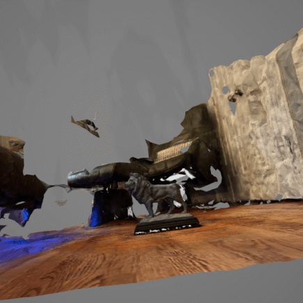
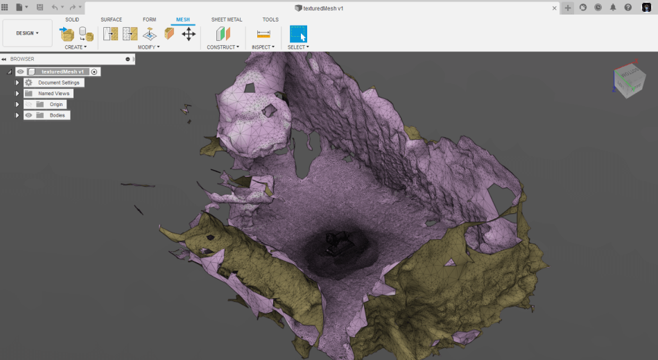
Just like in my first scan, once I had imported all images take of the lion bookrest, I ran a StructureFromMotion compute to see all generated points by Meshroom. After this process completed, I noticed the I was missing points along the underside of the lion, so I used the same night mode process used before to take some from the underside of the bookrest, imported these into Meschroom along with all the other images, and ran another StructureFromMotion compute. This point cloud looked(shown above) much better than the prior, and after its completion, I rendered the entire mesh by again, clicking the start button at the top of the interface. This render took just under 2 hours, and yielded a complete mesh of the lion, with relatively high detail on all parts except for some missing bits of tail.
Fusion 360 Mesh Processing
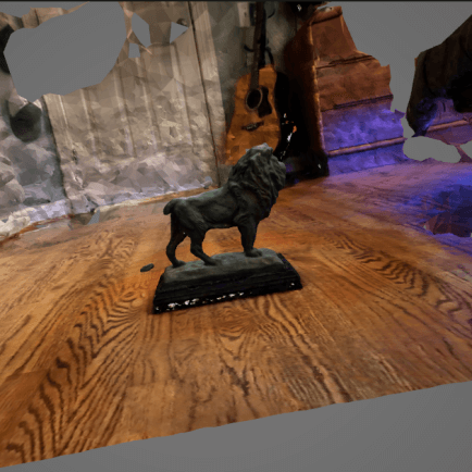
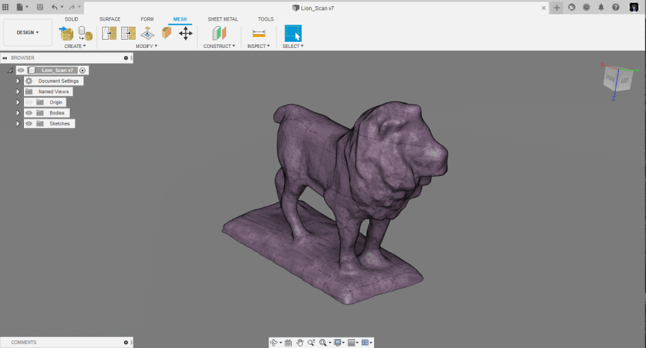
I was pretty happy with this final lion mesh generated, so I moved on to cleaning up the .obj files in Fusion 360s Mesh interface. One fault of using Meshroom to 3D scan an object is how good Meshroom is a creating point. After opening in Fusion, I found my lion model was surrounded with a large chaotic shape that meshroom put together representing the background in all of the images, so some cleanup was required to delete all this excess mesh from the part I wanted, the lion.
I used Fusion 360’s Mesh workspace to interact with my scanned mesh. To separate and delete the excess parts of my mesh I used the Plane Cut tool in the Mesh workspace. This allowed me to select a plane that I could cut into the mesh with, and delete the unwanted half. I used this tool to remove excess from all four sides of the mesh, as well as to flatten out the base bit of the model. Once I was happy with this and left with just the lion scan, I used the Make Closed Mesh tool to fill in any parts of the scanned mesh that were incomplete, and I was ready to export my model for 3D printing.
Printing and Postprocessing
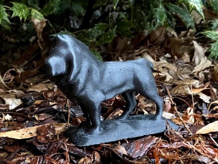
Following the same steps I used to 3D print my in-circuit programmer case, I imported my scanned lion .stl file into Cura and selected proper settings for my printer and material. I printed this lion scan with Galexly Black PETG from Prusa Research and was able to use the same material profile as well as the same quality settings as I used for my in-circuit programmer case.
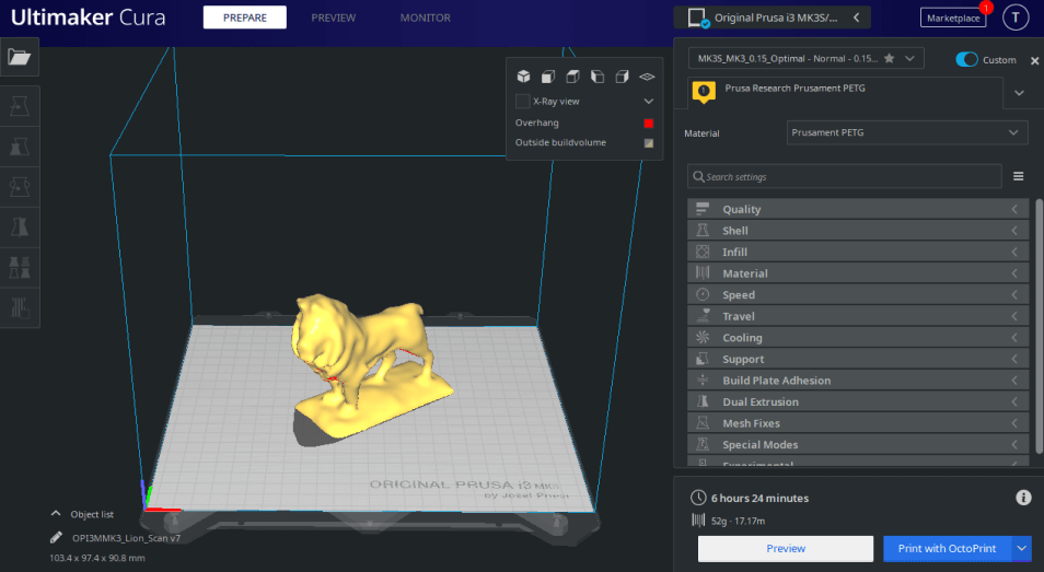
The lion took around 6 and a half hours to print, and again, I used Octorprint to film a nice timelapse of the entire print, shown below.
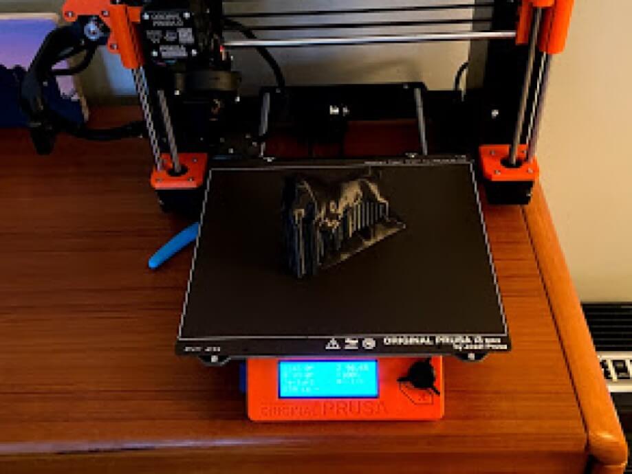
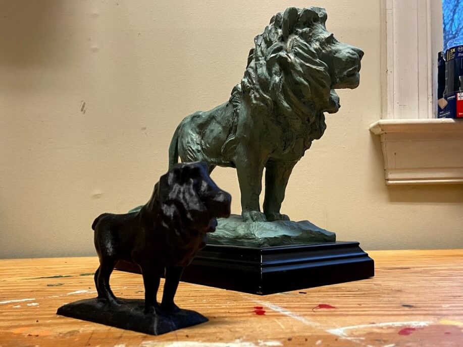
Again, the use of PETG while printing does me favors during post-processing. I removed all supports on the print with a pair of needle-nose plyers and cleaned up the surfaces using the hairdryer technique I used on my in-circuit programmer case, along with an Exacto blade and some files. Overall I think the lion turned out well, and I especially like how it looks in the Galaxy Black filament, which has a cool-looking glitter effect on the final print. In comparison to the original bookrest, the 3D printed lion is a little lower poly, but the model is certainly still recognizable, and therefore I can call my scanning and printing attempts a success.
Summary
I was really happy this week to come out with some successfully 3d prints from my 3d scanning files. It was pretty cool learning the photogrammetry practice, especially after it yielded good results. In addition to my personal work for this week, I picked up a good bit from my work testing our Ender 3 3D printers as a group. Our final printer test on our Ender 3s’ was a 3D Benchy test, a small boat model that tests important functions of a 3D printer. I had some prior knowledge of these different functions, but after knocking some rust off of these functions, I was able to see where each individual feature was tested on the 3D Benchy, helping me determine the specific problem areas in printer performance.
Group Work
This week’s group assignment was to Test the design rules on our 3D printers and explain what are the limits of our printers. We completed these tests on our Ender 3 3D printers we all build to take home during our Computer-Aided Design week and documented this whole process on our Fab Academy group page. Due to alterations I made to my ender 3 during CAD week, my printers settings did not line up with the rest of the ender 3’s our group tested this week, so because I couldn’t run tests on my personal machine, I prepared the printer tests STL files, and sliced some into gcode with my CURA settings, to share with our group classroom page. In addition to the file prep work, I also wrote a good bit of this week’s group documentation, along with my classmate, Graham Smith. Sections of the group site I worked on include the Terms and Definitions, Printing, a little bit of the test results paragraph, along with the pages media and downloads. Click here to view our group documentation site, with this week’s assignment on it.
Downloads
- Click Here to access and download all of my files from this week