13. Output Devices
This week I worked with output devices, setting up an LCD screen and interface for my final project, as well as fabricating a final project main board to test it on. (Apr 21)
21-27 minutes
My goal for this week was to create another component of my final project system, the tanks front display screen. My eventual goal is to hook this screen up to a board that is reading serial data from my input board and a PH sensor and then have that data written to the LCD in a readable format.
LCD Breakout Board
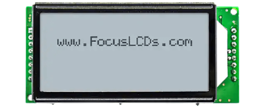
Just like so many weeks before it, I began this week’s assignment designing in Eagle and researching the needed components. I spent the better half of an afternoon searching for the perfect LCD for my assignment this week, as the space requirements of the mounting area, along with the need for a 20 x 4 LCD minimum to display all necessary info in a readable format made this search more difficult. Eventually, I stumbled on the C204C-FTW-LW65 from Focus LCDs, a vertical compact 20 x 4 LCD, shown below.
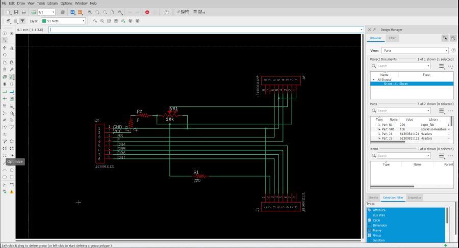
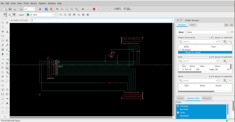
This LCD met all of my space and screen size requirements, and I began in Eagle creating a breakout board to the screen. This board will mount to the LCD, and break out the screen pins to the headers that will need to connect to a microcontroller. The premise of the breakout board was pretty simple, and I referenced the C204C-FTW-LW65‘s datasheet (included below) and attached the needed data lines from the LCD, DB4-DB7, to a set of breakout pins on the board.
I next hooked up the LCDs VCC and GND, as well as its backlight VCC and GND, to their corresponding power headers on the board. A 220 ohms resistor is included on the LCD backlight’s VCC line, to dim the light so the screen’s content is readable. The final portion of this board was a contrast adjusting 10k ohms potentiometer. This potentiometer provides a voltage to the LCD’s contrast adjusting pin, allowing the LCD character brightness to be altered, leaving me with the final schematic shown below.
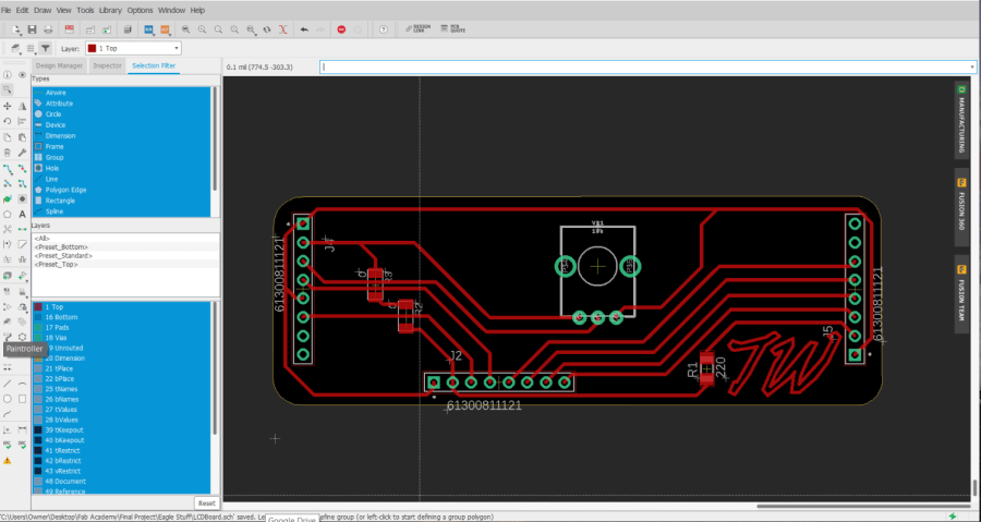
With this schematic flatted out, I moved onto converting this schematic into my LCD breakout board. Here I began again by referencing the datasheet, positioning the LCD mounting headers to the correct dimensions on my board to line up with the C204C-FTW-LW65 LCD. From here, I positioned the contrast adjusting potentiometer to mount on the backside of the board, allowing the LCD to mount directly over the breakout board, in the most space-efficient manner. From here, I also positioned the board’s resistor and jumper resistors, and then positioned the breakout headers towards the bottom of the board, before running all of the board’s traces. Due to the mounting position of this breaker board, the shape had to fit in as compact of a space behind the LCD as possible, so I dragged the boards outline down to fit around the boards content, and used Eagles miter tool to round over the board’s corners, leaving me with the boards shown below.
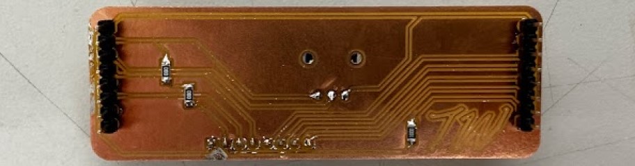
Although the components and routing of this board were correct, after milling and soldering this original LCD breakout design (shown in the image below), I realized I had positioned the board’s headers on the wrong sides of the board, leaving me with a breakout board that would have to be mounted in a poorly space-efficient manner.
I did a quick rework of the board and schematic while resolving this issue, starting with addressing the breakouts messy schematic, I reworked the routing, and also increased the resistance value of the LCD backlight dimming resistor from 220 to 330, after some breadboard testing. I found the 330 resistance value worked better than the standard 220 for my C204C-FTW-LW65 greyscale style screen and allowed for better readability.
After this schematic work was completed, I moved onto reworking the board design, flipping the header positions of each side of the board, to allow the board to be mounted with the LCD directly behind it, in the most space-efficient manner. I confirmed, just like in the previous board iteration, that the distance between these two header rows matched that of the LCD headers, and routed the breakout board, leaving me with the product below.

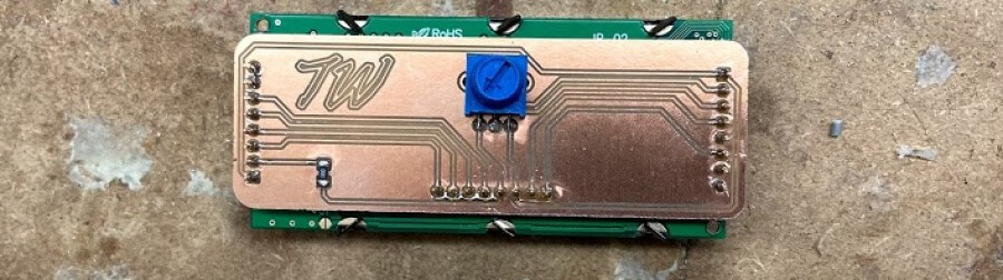
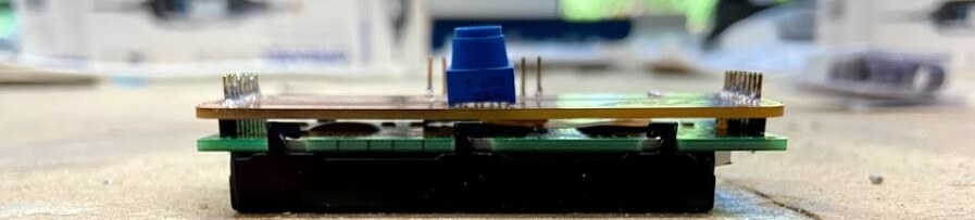
Due to its single 330 ohms resistor component and three-pin potentiometer, the milling and stuffing of this LCD breakout board weren’t super time-consuming, and I worked through it with relative ease. I first attached the breakout board to the backside of the LCD board, soldering the pins of the LCD to their propper pads on the breakout board. From here I tracked down the 330 ohms resistor, and also soldered the potentiometer in place. Finally, I attached the breakout board headers, that would allow for connections between the LCD and the board, leaving me with the LCD and breakout system below.
Main Fishbowl Board
With the completion of my LCD breakout board, I could begin work on the next part of my output system, the microcontroller board. Conveniently enough, I had started this process during the second half of my week 6 electronics design class, and have been iteration on the board since up until this week where Ill hopefully complete the board to use with my output LCD. For documentation on the starts of this board, visit my week 6 electronics design page.
Although I had begun the designing process of this board before this week, I had been unable to get a version working, and still had plenty of features I wanted to include. Because of this, I started the board work process by working back through all systems in the board’s schematic, familiarizing myself with the purpose of each system/component. From here, I started work on adding in a 12v to 5v voltage regulator on the fishbowl board, as in the future, I’m planning on running my final project fish tank on 12v, and this regulator will allow for this potential 12v system. I took advantage of a 12v to 5v voltage regulator in this regulator system, opposed to a variable voltage regulator, as the components on my fishbowl board will always be 5v, and thus the voltage can be set by the regulator itself. Along with this regulator, I included two 10uf capacitors between GND and VCC on the voltage regulators’ input and output, reducing portion noise on my board. Besides the addition of that system, the other systems of my fishbowl board remailed relatively the same as the original from my week 6 iteration of the board, minus the fact that the schematic’s systems have been moved around a little bit, with some reworking/wiring of the schematic.
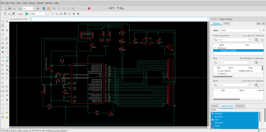
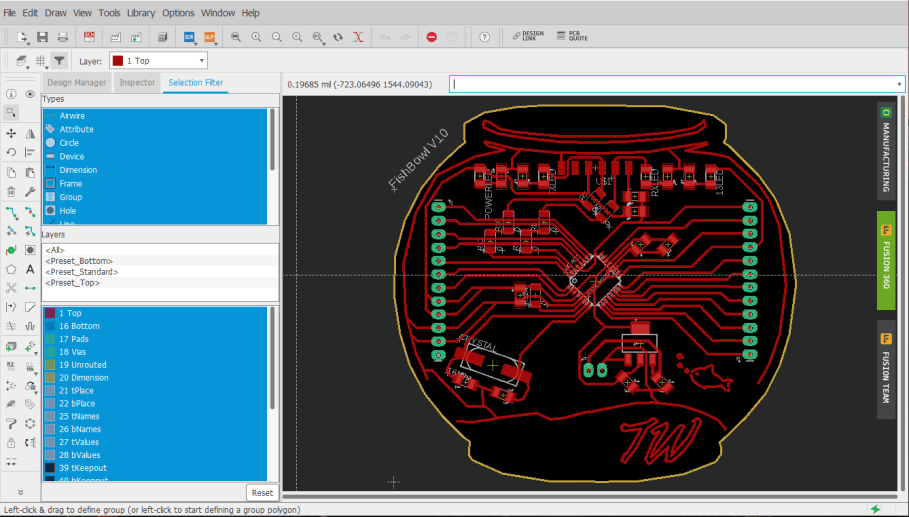
With the addition of these new voltage regulator systems, a rewiring of the fishbowl board was needed, and during this time around, I took some extra time to reduce the needed components on the board, and allow for easier soldering. After messing around in the board file for a bit, I found I could use one of my “Fish Bowl” shape decorative traces as a GND line that surrounded the entirety of my board. This line implemented a universal ground way more accessible from everywhere on the board and offered another solution to a problem I had previously addressed by using 0-ohm jumpers resistors to solve, routing GND lines over other traces with these “jumpers”. This surrounding ground line reduced the crazy amount of 0-ohm resistors on my board and made the board’s soldering/stuffing process simpler and less time-consuming.
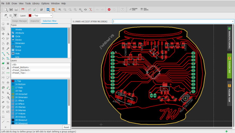
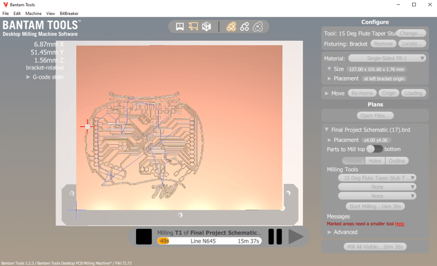
I milled this board following the same steps I used while milling boards previously in week 4, starting with the board traces operation with a PCB engraving bit. While iterating on this board since week 6, I’ve milled a handful of tests, some yielding successes in some systems, but always including another issue/broken system to flatten out. I next moved on to milling the board’s holes and outline, using a 1/32” bit for these two operations, before moving onto board soldering.
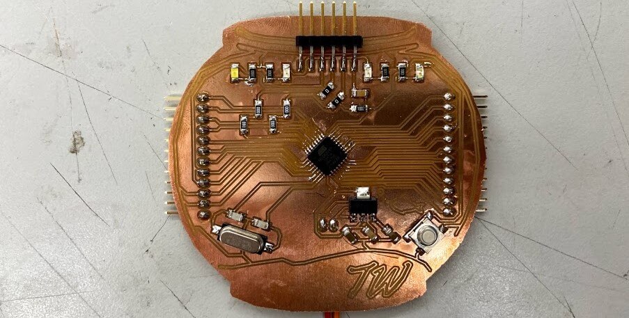
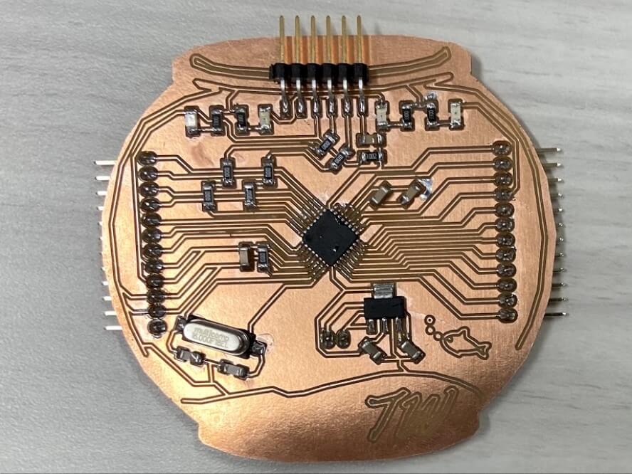
The part reduction steps I had taken earlier while encluding the wrap-around GND trace on my board paid off here, and the boards soldering and stuffing time had been greatly reduced. One thing that I’ve picked up on while soldering prior test fishbowl boards is a “drag” technique while soldering the ATMega to the board. I used this technique on these boards as well, first aligning the chip to its corresponding pins (ensuring correct orientation), before tacking down one of the pins of the chip to the board, and then dragging the tinned iron across one of the rows of pads, allowing solder to flow and connect between each of the chips pins and the board’s pads, and leaving me with a clean set of joints. With the chip soldered, I wrapped up the board by soldering all of the other components, finishing with the three largest components, the crystal, voltage regulator, and reset button, leaving me with the boards show below.
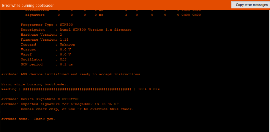
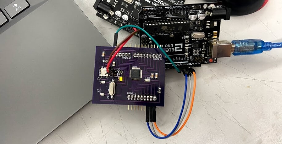
As the first test for this new fishbowl board, after soldering, I hooked up the board to a 12v DC power supply, and then probed the new voltage regulator output to test the output voltage. To my luck, the regulator yielded a 5v output and remained at a constant voltage throughout my probing. I next moved onto attempting to burn a bootloader to the fishbowl board. This process is similar to the one taken while burning the bootloader on my Sashakit made in our Student Bootcamp class. The bootloader is burned to my board through an Arduino acting as an ISP programmer, so the first step while attempting to burn the bootloader was to set up the Arduino. I uploaded the Arduino example skets, Arduino as ISP, to an Arduino board, and referencing the Arduino as ISP sketch, and my fishbowl board eagle file, I attached the two with some jumpers using the pins called on by the Arduino as ISP sketch. From here, I opened the Arduino IDE, selected the port my Arduino acting as a programmer was connected to, and then used the IDE’s Burn Bootloader tool, and … it failed. Unfortunately, even after triple-checking my wiring, switching my Arduino board, reuploading the Arduino as an ISP sketch, and ensuring my fishbowl board was receiving enough power from my power supply, I still received an error message upon any attempt to burn a bootloader. I tried this process a couple of times and received two different error codes, one of which is shown below.
A bit of research into the codes I was receiving helped me break down the problem a little bit, but not a ton. I found that there were three major potential flaws, however, a board short / VCC error, a “bricked” chip, or a non-oscillating clock, and decided to look into these three more. Being the easiest resolved I began looking into the VCC error a little more, starting by probing each of my board’s traces for continuity between places that should not be connected, and also probed the voltages of the GND and VCC line of the board when supplied power, however, all of these results looked normal. After a little more research of the matter online, as well as into the ATMega 328p, I noticed that it recommended to included a smoothing 100nf capacitor in between the chips AREF line and its nearest GND pin, so back in the board’s eagle file, I added this smoothing capacitor along with the previously existing 100nf smoothing capacitor running between two GND and VCC pins on my chip.
From here, I also explored the other two potential causes of my bootloader burning issue, however, I found no easy fix to a “bricked” chip, and therefore moved on researching a non-oscillating clock a little more. I found that similar to the “bricked” chip, a non-oscillating clock is not easily fixed, but can be avoided, as the clock will not turn to its non-oscillating state unless the fuses of the ISP programmer are incorrectly set. Confirming in my ISP programmer, I had the correct fuses set, and eliminated this as being one of my potential issues.
As a workaround to my inability to “Un-Brick” a chip, I followed the advice of one of my instructors, Dr. Adam Harris, to test the working of my chip before using it on a board. To do this, I soldered up a Sashakit board, just like I had in my Student Bootcamp class, however, I left the chip unsoldered to this board. I was then able to connect this Sashakit board to an ArduinoISP programmer, and then use it to try out the bootloader on multiple chips. I aligned a chip with its corresponding pads of the sashakit, heald it down in the center with a pair of tweezers, and used the Arduino IDE to burn a bootloader to my board. All this worked! and the Arduino let me burn a bootloader to a couple of different chips, however, I did find some other faulty “Bricked” chips along the way. Despite that, I was left with a couple of chips with bootloaders burned, that I could be sure were working, and was able to eliminate another potential issue on my board.
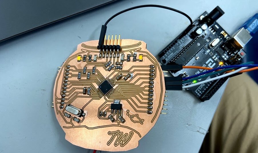
With all this troubleshooting into my issues at a stopping point, I was ready to manufacture another board iteration, going first milling the PCB,
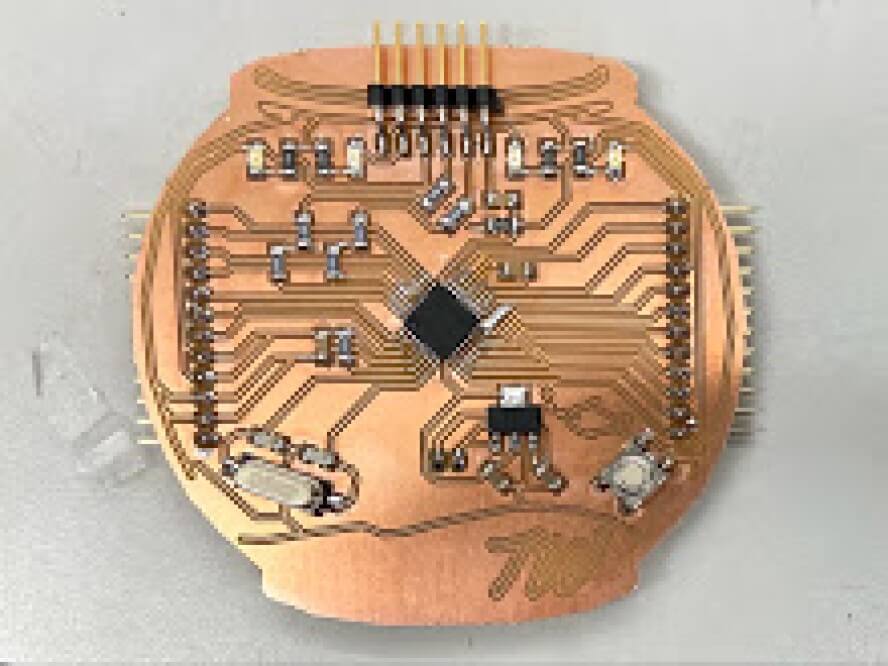
then soldering and stuffing, leaving me with the board shown below.
Due to my previous failures with this board, I was pretty nervous to test this iteration and started my first just powering up the board through a power supply. Unfortunately, this simple startup produced a cloud of smoke from the top of my board, and the board’s voltage regulator exploded. This error sucked, and ended up stemming from the misplacement of a strip of 5v to 3.3v regulators in a bin meant for 12v to 5v (the ones needed by my board), and the false component use ended up frying one of my bootloaded chips. I unsoldered the remains of the busted voltage regulator, as well as the fired chip, and replaced them with working correct components. I tested the board with power again, this time fortunately without explosion, and was ready to attempt to program the board again. I wired the board to an Arduino with the Arduino as ISP sketch flashed to it, and tried to upload a blink code … no luck. Upon this uploading attempt, the uploading process began, and then returned error 0x0000000, a GND or Reset error.
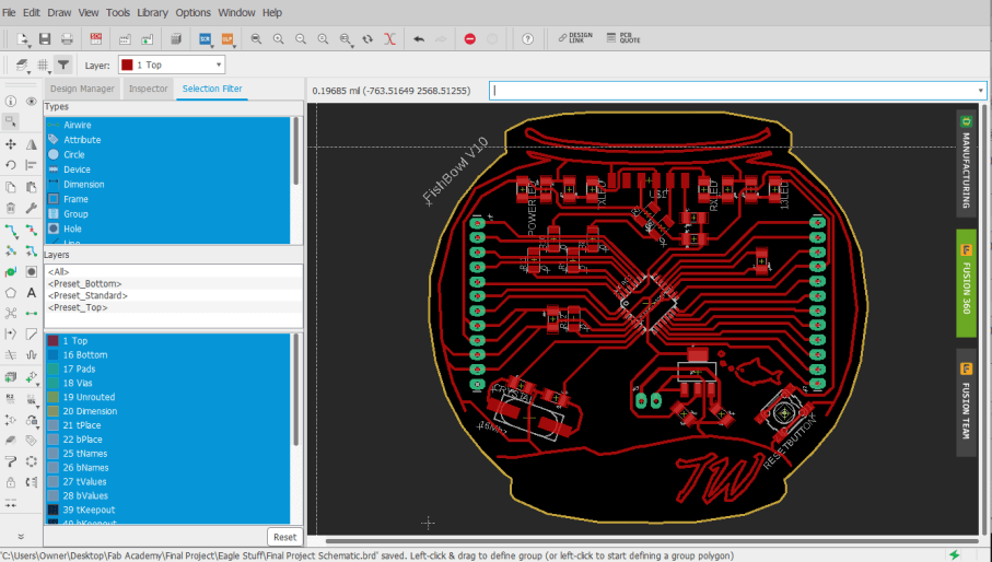
Here I went back to my schematic, and went through the system by system, and referencing the datasheets for major components. I wanted to make sure to include all recommended/required components for components on each of their pins. In addition to what I already had, this included adding a larger smoothing capacitor between GND and VCC, another capacitor between AREF and its closest GND pin, as well as an additional RST pin, without the 100nf inline capacitor. After a board works though with Dr. Adam Harris, I also moved these additional smoothing capacitors closer to my board’s ATMega 328 to reduce any resistance build upon the traces. All of these changes left me with yet another board iteration, shown below.
Again, I worked through the manufacturing process for this board, first milling, and the soldering and stuffing the board. All of these board iterations have sped up their production time, as I know have the component layout of the board memorized, and have increased my soldering speed with each iteration.
Just like the prior iterations, I wired up this board to an Arduino with the Arduino as ISP example sketch flashed to it, and attempted a bootloader burn, this time, yielding successful results!! I was able to burn the bootloader to this board without error, and also begin to upload codes to the board, as discussed later on this page.
Programming
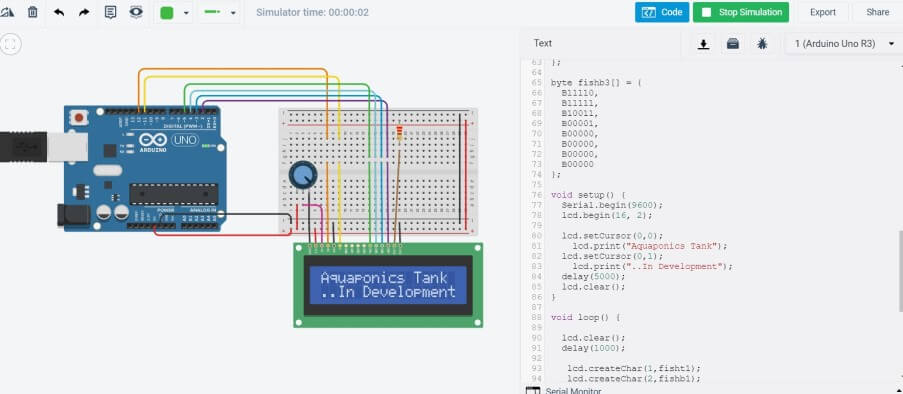
Although I had some setbacks in the board design of both my LCD breakout board and my fishbowl main board this week, I was able to stay on top of the LCD programming when not working on these boards in our lab. I began the programming process with a little experimentation with LCD code in a Tinker Curcits simulation (shown below), trying out setting up the LCD in code and then printing characters to the LCD.
With some of this experiment done of a simulation end, I was next ready to test out my LCD in the real world. Unfortunately at the time of these first tests, I had not gotten in our lab to mill the updated LCD breakout board and had to resort to a breadboard jumper setup, along with an Arduino for testing. I referenced my unmilled LCD breakout board while wiring the LCD to the Arduino, also including a 220 ohms resistor, dimming the backlight, as well as a contrast adjusting 10k ohms potentiometer.
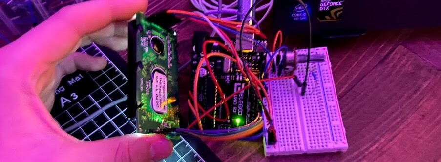
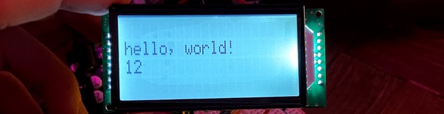
As the first test with this wired setup, I uploaded an instance of the Liquid Crystal Hello World Arduino example sketch to my Arduino, only changing the LCDs setup size to match the dimensions of my LCD, as well as the cursor positions when printing the Hello World text and counter below.
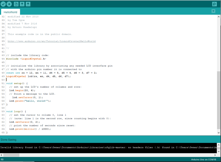
Upon upload of this code to the Arduino LCD circuit, It worked! With a little adjusting of the contrast adjusting 10k ohms potentiometer, I was left with a programmable, readable LCD, that I could next move onto programming.
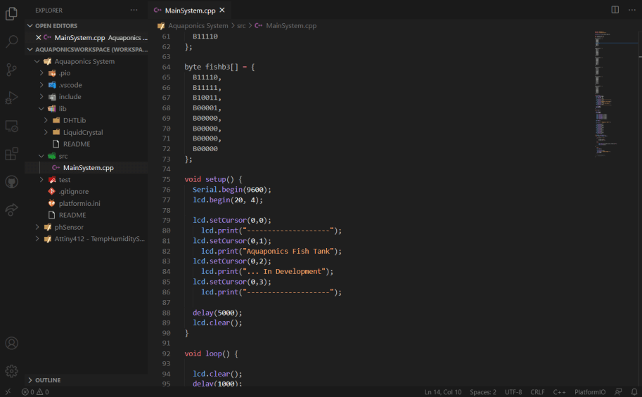
I began writing out the code for a simple LCD interface in VSC with PlatformIO, an IDE I used in my week 8 embedded programming class. My basic goals for this interface are to eventually display input values from the sensors on my final project fish tank, a goal that I plan on starting this week, completing the interfaces boot screen, and status display, before finishing the reading of inputs during next weeks Networking and Communications, where I can worry about the communications between my tanks inputs, and the LCD and board.
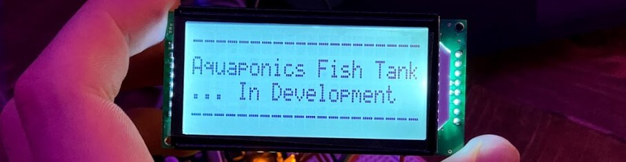
I started the LCD code with my prior hello world test and Tinker Circuit test codes as a reference. The code utilizes the Liquid Crystal Library included by default in the Arduino library for LCD control. Breaking down the code, there are two sections of my LCD interface, a boot screen, and a status display screen that will in the future, provide information read from my Aquaponics fish tank’s sensors. After my experiments with LCD code in Tinker Circuits along with some reference to a Liquid Crystal Display Library page, I had some ideas on how to implement an LCD boot screen and wrote out the boot screen code in the void setup function of my code. The boot screen code is a simple display of characters spanning the width of the LCD, with the top and bottom lines being filled with -, and the middle lines displaying the text Aquaponics Fish Tank and … In Development. The inclusion of this boot screen in the Void Setup function of my code shows this boot screen upon bootup of the system, and the function includes a short delay while displaying the screen, allowing all of the input sensors to get started up and begin future communications with the mainboard.
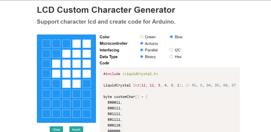
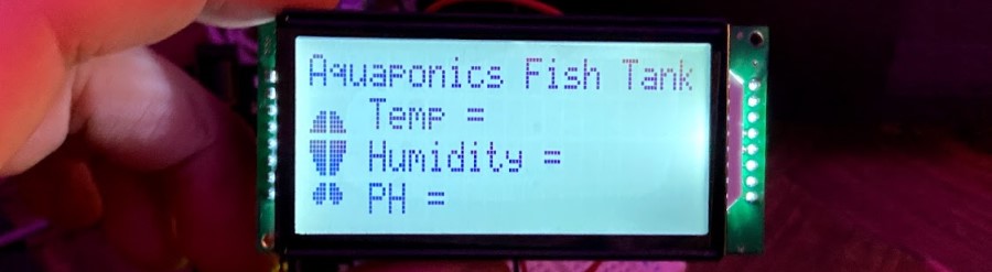
From this boot screen, the interface next moves into its status screen display. It was here where I planned on taking full advantage of the 20 x 4 display size of my LCD, and decided to create some custom characters to include a fish icon on my status screen, as well as include an Aquaponics Fish Tank title. I began this status screen creation with some research on the creation of custom characters, where I found this Hackster.io article to give a good description of the topic. The article is linked to an online LCD Character Creator, where a GUI is provided that converts a drawn character into the hex codes that can be written to an LCD in code. I used this generator online to create a 2 x 3 character fish and was able to copy the generated characters generated into my LCD code.
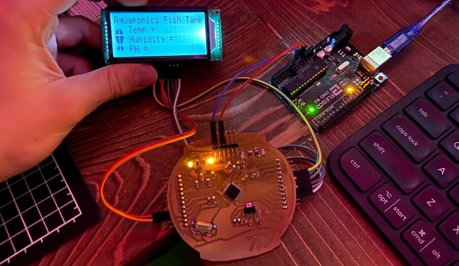
I began the status screen code in the Void Loop function of my code, where I started by including an Aquaponics Fish Tank title printed at the top of the display. Following this, I called upon each of my 6 custom characters established earlier in the code, positioning each of them to create a 2 x 3 fish icon on the left side of the screen. The final touch to this first iteration of the status screen would be indicators for Temp, Humidity, and PH, each receiving their line in the interface. In this instance of the status screen, these indicators are just text displayed on a set line of the interface, to the right of the fish icon, however, these placeholders leave me a place to stem off of next week, where I plan on parsing information being sent in via serial, and printing the proper values to their corresponding places in the interface. All of this left me with the first iteration of the status screen, shown below.
Testing Code on Fish Bowl Board
After all of the troubleshooting that went into my fishbowl board, it was super nice to finally have to worry about code. I began this fishbowl board programming process with a simple blink sketch, and uploaded the Arduino IDE Blink example sketch to my fishbowl board via an Arduino as ISP programmer, yielding a successful upload shown below.
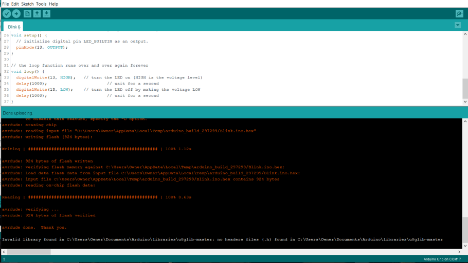
This simple sketch proved the working of my board and flashed my onboard pin 13 LED on my fishbowl board.
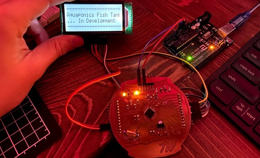
With all of my code flatted out on an Arduino previously, the testing on my Fishbowl board was pretty straightforward. I first wired the Fishbowl board with my LCD code uploaded to it, to my LCD and breakout board, referencing the breakout board’s schematic and the LCD code throughout. From here I ran 5v to my fishbowl’s 5v headers from and Arduino, and boom! my system worked.
Group Work
This week’s group assignment was to characterize the voltage and current needs of output, something we tested on a DC motor. This week’s group work setup and testing were carried out by my groupmate Drew Griggs, who tested our DC motor with a power supply and took note of the power needs of the device. Although drew completed the hookup of this motor to our power supply, I watched along monitoring the current and voltages drawn by the device. Click here to view our group documentation site, with this week’s assignment on it.
Downloads
- Click Here to access and download all of my files from this week