7. Computer Controlled Machining
This week I worked with our lab’s ShopBot PRSalpha to manufacture the large plywood fish tank housing for my final project, and also worked with our group to test run out, alignment, speeds, feeds, and toolpaths for our ShopBot PRSalpha. (Mar 10)
18-23 minutes
Fish Tank Design Work
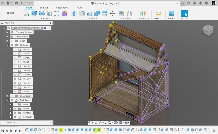
For this week’s “Make Something Big” assignment, I settled on making the plywood structure for my final project on our labs ShopBot PRSalpha CNC machine. Every once in a while over the course thus far I’ve spent a little time working on a Fusion 360 model of my Aquaponics tank, and started this week by flattening out the wooden section of the tank. Although this work yielded an overall body I was happy with, this body wouldn’t be enough to manufacture, and I spent a little time converting this design into different grouped components in Fusion 360. These different components allowed me to better picture the different cuts I would have to make on the CNC and also helped me picture how they would manufacture and assemble the model in the real world.
With the wooden structure of my final project model flattened out, I started to put some thought into the manufacturing processes I would need to take to produce this structure in real life. I settled on milling 6 different pieces to assemble the structure, one back wall, two sides, and3 stacked pierces to make the base of the structure. I planned on creating these parts based on their corresponding components in my Fusion 360 design. For each of these pieces, I created a new sketch on the face of the profile and used Fusion 360’s Project tool found under the Sketch menu to project all desired lines for each part into one single sketch in the Fusion 360 browser. With all of these lines in one single sketch for each of the 6 different components, I could export each sketch from the Fusion 360 browser onto my computer as a .dxf file by right-clicking on the sketch, and then selecting export as .dxf.
Before continuing with the tool path generation of this exported.dxfs, I decided to cut each of the files scaled-down out of cardboard on one of our lab’s laser cutters. I quickly imported all of these .dxf files into CorelDRAW and then printed them on our labs Epilog Fusion Pro 48. Although this test was not to prove the working of any of the connection pieces of my design, the scaled-down physical model confirmed to me that all of the pieces would sit together in the intended orientation.
This cut on the laser also revealed some vector flaws to me, as some of the lines in the files cut twice on the laser. To fix this, I imported each of the .dxf files I had exported from Fusion into Inkscape. For each of these files, I first right-clicked on the file and selected Ungroup. Next Under the Path menu, I converted all of the parts of each file into a path with the Object to Path tool before regrouping all of these paths by again, right-clicking, and then selecting Group.

After all this vector cleaning work was done in Inkscape, I saved each of these files as a Plain SVG file under the Save As command in Inkscape, so they were ready to import into Aspire. Although Aspire can handle .dxf files, I found after running into errors altering .dxf files in Aspire, that .svg vectors seem to work much better in the interface. Some of my exported .dxf files would import into Aspire with missing curves, and other features, so I converted each on my .dxf files into .svg files in Inkscape before attempting to open them again in Aspire.
Toolpath Generation In Aspire
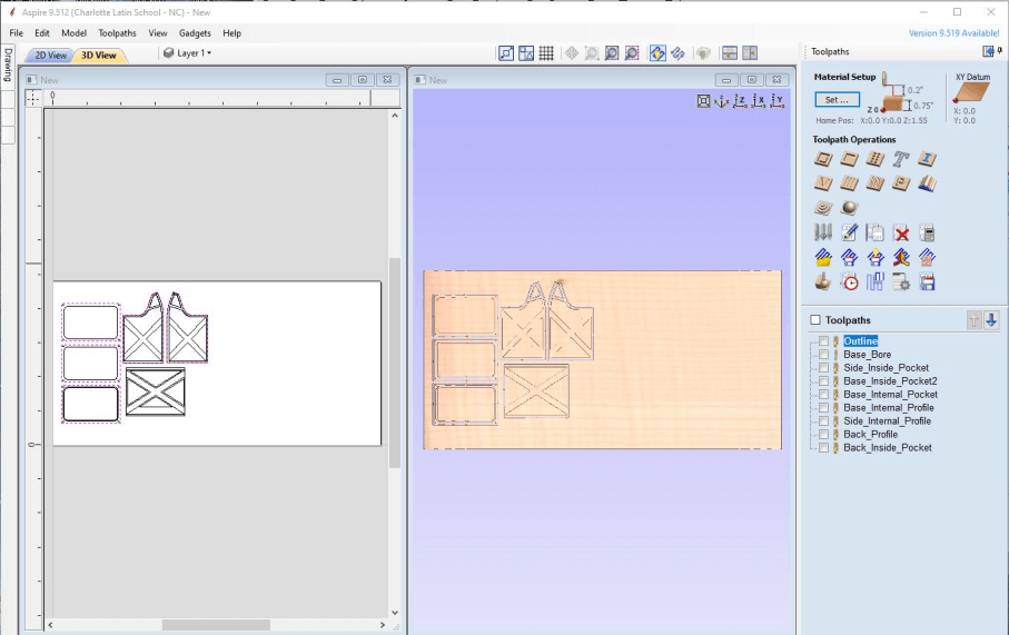
To generated the toolpaths I would later run on a CNC machine from my altered .svg files, I used Vectric CNC’s Aspire CAM software. I firstly created a new file in Aspire, where I was prompted to set a workplane size. The workplane of the ShopBot PRSalpha, the CNC I would be milling on, was 96” x 48”, and my material height was 0.776”, so I entered these value in the prompt accordingly. I then imported each of my .svg files into Aspire, nesting the files as I imported to reduce waste stock material. I spent a little more time with all of my files imported messing with the part orientation to ensure that there would be little stock material waste between my parts. In the assembly of my design, I planned to use milled tabs to align the back piece to the structure’s two sidewalls and created this feature in my design. Before making toolpaths however, I had to alter this feature to become millabe on the CNC, using Aspires Fillet tool found to the left side on the interface to add “Dogbone” fillets to the external corners of the tab holding slots on the sidewalls of my design. These “Dogbone” fillets are required to create a millable toolpath for the cylindrical bit to take in a square profile. The cylindrical nature of the endmill bits I used to make it impossible for the bit to mill out a perfect rectangular profile from the inside, and thus these “Dogbones” are needed to give the bit a place to go ensuring enough material is removed for the backplates tabs to fit. With these “Dogbones” flattened out, I then switched over into Aspires 3D View by clicking on the tab labeled 3D View at the top of the interface’s workspace. Here I could start working on generating the different toolpaths for my parts. Throughout this process, I referenced my original Fusion 360 design to determine which sections of each of my files would require different toolpath operations. The first toolpath operation I generated was a Boreing operation that would bore holes for alignment dowels in the base of my structure. This operation was especially needed in my operation as I was not planning on switching to a drill bit anytime throughout the milling process, and this boreing operation allows me to mill these holes with an endmill instead. Nextly I generated Profile toolpaths for all of my parts, outlining each of my files, and cutting them out. I selected all intended profile cuts for each of my files and set the depth of each of these profile cuts to 0.776”, the thickness of my stock material. This cut depth would ensure all of my profile cuts would go all the way through the material. Nextly I selected a .25 Endmill bit for both my profile and boreing operations, as this was the endmill I was planning on using. To prevent the movement of each of these parts after the profile cut completes, I added tabs to the toolpath under the Edit Tabs section of the toolpaths settings. These “Tabs” leave a small bit of stock material connecting the profile to the rest of the stock and holding their position. I found adding 3 to 4 tabs per profile, depending on size and shape, worked best to hold my parts in place. The final tool paths I generated were pocket cuts. These toolpaths remove material to add depth to some of my parts. These pockets were relatively straightforward, as they didn’t require any added tabs because they cont cut through the material, however, I used a different, larger, bit size for these pockets to speed up milling time, so I was required to change that. After this, I generated the pocket toolpaths for the “Dogbone” slots in my design. I generated this tool path separately as I was planning on using a 1/8” endmill, over the 1/4” use on other profiles, due to the small clearance required by the positions of these slots. Finally, before exporting any of these toolpaths, I went back through and turned on “Ramping” for each operation. This setting moves the Endmill bit in a diagonal fashion, as opposed to vertical plunges and then horizontal movement, allowing the side of the endmill to cut material as intended. I saved all of these toolpaths from Aspire through the Save Toolpath menu. Each of these toolpaths was saved under the Shopbot format, .sbp, and grouped based on the bit used. This left me with 3 different .sbp files for each a 1/8”, 1/4”, and 1/2” bit.
Manufacturing
Now with the toolpaths generated for my fishtank structure, I was ready to start the manufacturing process for the structure. One of my instructors, Tom Dubick, has a written workflow for machine operation that I referenced throughout the milling process. This workflow is attached below.
Material and Machine Prep
The first step in the milling process is machine and material prep. Our shopbot comes equipped with proximity switch endstops, as well as a z-probe plate, making this prep work pretty automated. Once I got on the machine I opened the Shopbot Command Console application on a computer connected to our CNC and ran the command
C3
in the ShopBot terminal, which homed the x-axis and y-axis by using the machine’s proximity endstops. Once completed, the gantry was located on the machine’s origin, and I jogged the machine towards the center of the workplane where I positioned the z-probe plate under the gantry. This plate remains connected to the machine throughout the milling process, so this task simply required moving the plate from its mount onto the workplane underneath the tool. It was here where I also installed the first tool I would be using, in my case a 1/2” straight 2 flute endmill for the pocket cuts in my design. While installing this bit, I was sure to first disengage the tool, before loosening the collet and installing the bit with two wrenches. I then reengaged the tool, and with the z-probe plate positioned underneath the tool, ran the command
C4
in the ShopBot terminal, and watched as the machine slowly lowered the tool towards the z-probe plate until it made an electrical connection between the plate and the tool. Then I removed the z-probe plate from the material, placing it back into its mount, and re-homed the machine back to the found origin. With the machine homed and tool installed, I next moved onto material prep. Firstly I jogged the gantry to the x-axis limit, moving the tool out of the way to where I would need to place the material. My stock material used was a sheet of red maple plywood, and with the help of my classmate, Graham Smith, I moved this sheet onto the bed of the CNC, aligning it to the origin of the machine, before fastening it to the bed. This alignment would make for a harder time later, as I did not leave a gap here to re z-probe the bed after a tool change, but instead, covered the whole be in my stock. I faced my stock material to the machine bed with some wood screws, positioning a screw in each corner of the stock, as well as one in the middle of each of the longer sides, references my toolpaths to assure I was not placing a screw in the way if a toolpath.
Cutting Air and Milling
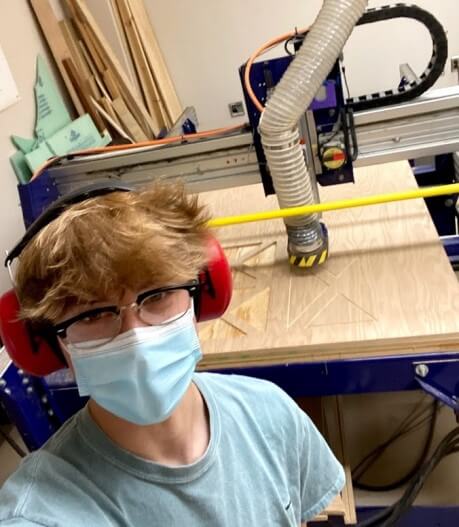
After this machine prep, I was finally able to move onto the milling process. My classmate Graham Smith and I did all of our millings this week together as the operation of a machine on this scale can be unsafe if the right precautions are not taken, or if operated alone. I loaded my first tool path, my 1/2” pocket operation, into the Shopbot Command Console through the Load File menu under the File tab. I selected my .sbp toolpath, and under the pop-up menu, selected 3D Offset as the operations offset, and then proceeded to click enter to start the cut. This “3D Offset” allows for me to complete an “Air Cut” of my file, where the tool doesn’t engage with my stock material but just runs above it. I ran this Air Cut to ensure my part placement fit with the side of the machine’s workspace limits, and also didn’t run into any screws. This test of cutting air was successful, so I was ready to move onto the real milling operation. I loaded the file into Shopbot Command Console following the same steps taken previously, but this time I left the offset dropdown set to the default No Offset as opposed to 3D offset, so the machine would run another air cut. Before running this operation, I ensured the machine’s dust collection was turned on, and then clicked the enter key to start the operation, and when prompted, clicked the spindle start button.
Tool Change
With the completion of my pocket operation with a 1/2” bit, I had to make a tool change to a 1/4” bit before running my next cut. I homed the machine back to the origin, lowered the dust boot, and changed out the bit in the collet.

It was during the next step where I realized the unfortunate truth talked about previously, I hadn’t left room on the bed of the machine to reset the z offset with the z-probe after a tool change, and at this point, moving the stock would ruin alignment between the two operations. After a little thought on what to do next, Graham and I solved this probing problem by drilling a hole through the stock in the bottom left corner of the bed that was larger enough to fit the z probe. With this hole drilled, I jogged the machine so the tool was aligned with the hole, put the z probe plate in the whole, and then reprobed with the command
C4

Then, after removing the zprobe plate from the workplane and remounting it to the gantry, I rehomed the machine to the origin and was ready to continue with the next milling operation. I used the same process used for the prior pocket cut to first test my 1/4” profile operation by cutting air and then continuing with the milling of the structure. My intent after this was to repeat this same process of changing the tool and starting the milling operation with a 1/8” bit for the dogbones, however, I found that our lab didn’t have a 1/8” bit with flutes long enough to cut through 3/4” stock, and Unfortunately I had renested some parts in Aspire before milling and didn’t save my work, so there would be no way to regenerate the dogbone tool paths with a 1/4” bit and align the slots properly. This lack of prior checking for the bit size as well as a lack of lab time due to this week falling on out highschools spring break week, lead me to use the components I had milled with the prior two operations, and come up with another method to join the parts of the structure.
Assembly and Post-Processing
After the finishing of each milling operation, I used a chisel and mallet to break any tabs holding the parts to the rest of the stock material, before removing the pieces from the bed of the machine.

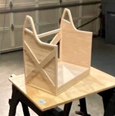
With the completion of all of the milling for my fish tank structure, I was ready to start the post-processing and assembly process. I decided to start base upon this process and first worked on the three stacking components making up the base of the structure. I sanded all of the milled pieces for the base of the structure, as well as the other milled components with a 120 grit sandpaper on my orbital sander, before cleaning up the pieces by hand with 120 and then 220 grit sandpaper. I then started the assembly of the base, first lining up all 3 of the layers before adding some wood glue between the layers, and inserting the 4 alignment dowels in each of the base’s corners with a hammer. I clamped the layers together on each side of the base, wiped up any glue squeezeout, and let the structure dry overnight.


I next faced the task of figuring out how to continue with the assembly with the lack of tab slots on the sidewalls of my structure. I decided to chop off all 4 of the tabs on the back wall of the tank with a hand saw, cleaning up the cut with my orbital sander, and then attach the parts with some dowels and wood glue.

Using a speed square and a ruler, I marked some locations to drill 15/16” holes for dowels on the sides of the tank structure and then drilled these out with a hand drill and a paddle bit. These measurements for hole location ensure that the two sides still stay symmetrical and that the dowels line up vertically on the sides. of the structure. I then aligned the sides and back walls against the sides of the base, used some painter’s tape and clamps to hold these pieces tightly together, and marked the locations of these dowels holes on the base and sides of the back, before unclamping and taping and drilling these holes. I repeated this taping and clamping process, this time adding wood glue on connecting surfaces, and then going through installing dowel pegs in the dowl holes. I used a small hammer to hit a longer dowel into each hole, before cutting off the excess with a hand saw, and then using some sandpaper to clean up the cut as well as the end of the longer dowel before moving onto the next hole. Once all of these dowels were installed, I clamped the structure, applying pressure to joining faces, and again, left the glue to dry overnight.

One thing I noticed after milling was a not very pleasant amount of splits and cracks in the middle layer of plywood exposed by the pocket operations on the sides of my fish tank structure. After completing the assembly on the structure itself, I cleaned up any cracks or gaps with some wood filler and a putty knife.


I gave this filler a couple of hours to dry and then remove any excess with some 80 grit sandpaper, before giving the entire structure a final sanding in the first 120 girt sandpaper, and then 220 as a finishing grit.

To finish up the fish tank structure that will be the bones of my final project, I laser cut a press-fit acrylic bottom panel for the base of the tank that will cover the electronic housing cutout located on the bottom of the tank structure. I followed the same steps take earlier this week to export the bottom panel as a .dxf file from Fusion, but instead of worrying about toolpaths for this file, I imported the .dxf into CorelDRAW and then, following the same process I took in week 3, I laser cut this file from 1/4” acrylic on our labs Fusion Pro 48 laser cutter.


Group Work
In this week’s group assignment, we characterized runout, alignment, speeds, feeds, and toolpaths on our labs ShopBot Desktop MAX CNC machine. I started off the group work process by working with a few of my group members to research the different terms we would be testing and ways to test them on the machine. Using our labs ShopBot Desktop MAX workflow as a reference, I then began the machine testing with some help from two of my group mates, Charles De Mey and Jack Hollingsworth, first aligning the machine, then testing run out, and finally milling a toolpath test. With these tests complete, I then uploaded media from the test to our group page which can be found here.
Downloads
- Click Here to access and download all of my files from this week