(9) Embedded Programming
This week we were asked to individually read the microcontroller data sheet and program a board in as many programming languages possible in different environments. Additionally, as a group we were expected to compare the performance and development workflows for other architectures.
Data Sheet & Background Information
Prior to attempting to do anything with the electronics, I first needed to read the data sheet to understand how the microcontroller functions; furthermore, I was going to have to read the long and daunting instructions of the chip. Before diving into reading, I first wanted to know what kind of information is most relevant and to search for. Our instructor recommended a very helpful resource from sparkfund about how to read datasheets; this is linked here: https://www.sparkfun.com/tutorials/223
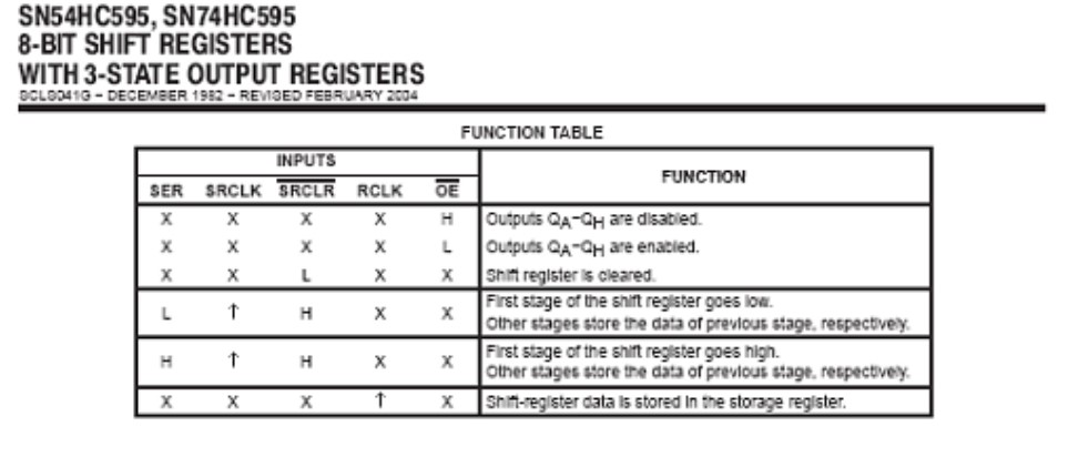
While data sheets can be difficult to read, as they are often written by engineers and can be lengthy, they serve a fundamental purpose in comprehending how a specific component functions. The first section of a data sheet typically consists of a summary of the part’s feature and functionality and sometimes diagrams to demonstrate internal aspects of the part. Frequently, data sheets also include a pinout list of where the different pins are and their use, as well as recommended operating conditions: voltage and current ranges, timing information, temperature ranges, and more. Truth tables show how altering the inputs will affect the outputs with each line having each of the parts inputs as a certain value with the corresponding output. “X” means the input is irrelevant, “H” means the input is a logical high (usually VCC), “L” indicates a logical low (GND), and an arrow indicates that you need to change L to H or H to L. Changing the H and L of an input is often referred to as “clocking” an input, which is essential for the functionality of many microcontrollers.
Additionally, timing diagrams show the rate at which data is received and sent, which can be extremely significant depending on the user’s intended application for the part. For example:
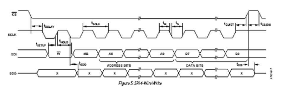
Example schematics, part dimensions, and common issues/ recommendations may also be included by the manufacturer in the data sheet; however, those are more self explanatory
I also referenced a helpful Sparkfund Video explaining the more technical side of microcontrollers, using the ATmega328P as an example. – https://www.youtube.com/watch?v=6q1yEb_ukw8
ALU (Arithmetic Logic Unit) = Responsible for executing mathematical operations; follows program/ series of instructions uploaded to the board
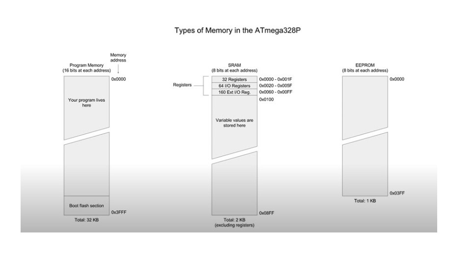
32 x 8 General Purpose Registers = Where data (instructions for the ALU) are stored .Special Function Registers (SFR) = Unique to part’s architecture: used to control pins, send/ receive data, define variables in arduino language etc. SRAM = Static Random Access Memory: Used to store current data which is cleared later when not in use (Ex: values for variables) EEPROM = Slower read and write prompts, but can store data when power is lossed
More referenced Videos:
Registerers – https://www.youtube.com/watch?v=tBq3sO1Z-7o Set Registers by Memory Address – https://www.youtube.com/watch?v=W8REqKlGzDY
Arduino Port Registers – https://www.arduino.cc/en/Reference/PortManipulation
Port registers allow faster manipulation of i/o pins of a microcontroller on an Arduino board. On an Arduino board, it uses the ATmega8 and ATmega168, which use three ports: B (digital pins 8 - 13), C (analog input pins), and D (digital pins 0 - 7) with each port controlled by three registers.
DDR register - input or output Port register - pin High or Low and it reads the state of input pins set to input with pinMode()
Digital Pins 0 - 7 for PORTD: DDRD - The Port D Data Direction Register - read/write PORTD - The Port D Data Register - read/write PIND - The Port D Input Pins Register - read only
PORTB maps to Arduino digital pins 8 to 13 The two high bits (6 & 7) map to the crystal pins and are not usable DDRB - The Port B Data Direction Register - read/write PORTB - The Port B Data Register - read/write PINB - The Port B Input Pins Register - read only
PORTD maps to Arduino digital pins 0 to 7 DDRD - The Port D Data Direction Register - read/write PORTD - The Port D Data Register - read/write PIND - The Port D Input Pins Register - read only
PORTC maps to Arduino analog pins 0 to 5. Pins 6 & 7 are only accessible on the Arduino Mini DDRC - The Port C Data Direction Register - read/write PORTC - The Port C Data Register - read/write PINC - The Port C Input Pins Register - read only
I would be programming my week #7 electronics and design button board, which uses a ATtiny412 chip; the data sheet for the microcontroller is linked here: http://academy.cba.mit.edu/classes/embedded_programming/t412/40001911A.pdf
Initially, simply by the size of the document it was intimidating; however, the background reading prior definitely provided some key knowledge on different terms and the layout of the data sheet.
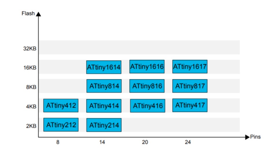
This chart, though not relevant to embedding programming now, I wanted to save as it will prove useful in determining the type of chip I might need for my final project based on the type of procedures it will be doing and the number of pins for inputs and outputs. The ATtiny412 chip has 4KB of flash memory and has eight pins, which is adequate for this assignment, but looking forward, the 412 chip will not be enough for my intended final project.
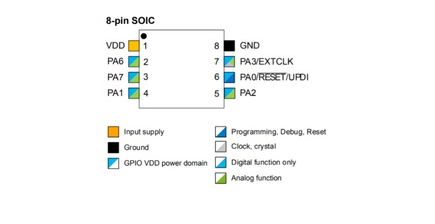
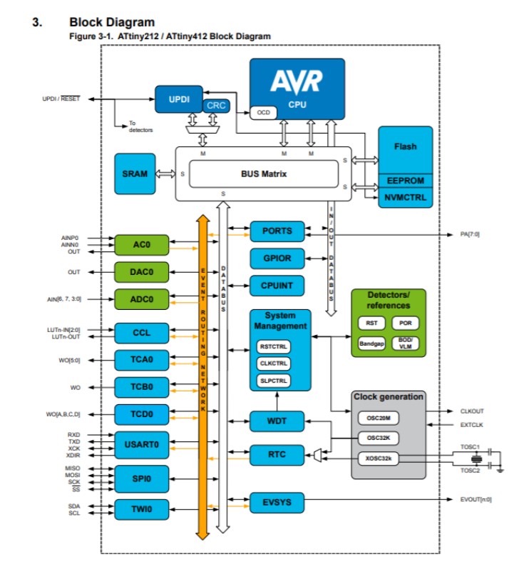
This image illustrated the use of each pin on the microcontroller and how they were positioned on the chip. The block diagram also breaks down each aspect and component of the ATtiny412. Before, the internals and parts of a microcontroller were foreign to me, but the diagram allowed me to clearly visualize how the chip operates.
Next, the data sheet explicated the details about the memory on the chip and how the PDI/ CPU data space was divided. The flash memory space is divided into the Boot Loader section, the application code section, adn the Application data section. It also explained the environment the chip can function in, which ranged from -40 C to 125 C. While that is not relevant to our usage, it is important to understand that engineers who deal with extreme environments have to account for these factors, among many more, especially when it’s not simply a dollar chip, but a more expensive larger scale project, such as in NASA’s Mars Perseverance Rover. Although I scanned a lot of the data sheet and only read several dozen pages of it, it proved highly effective in informing me about the details of the microcontroller I am using.
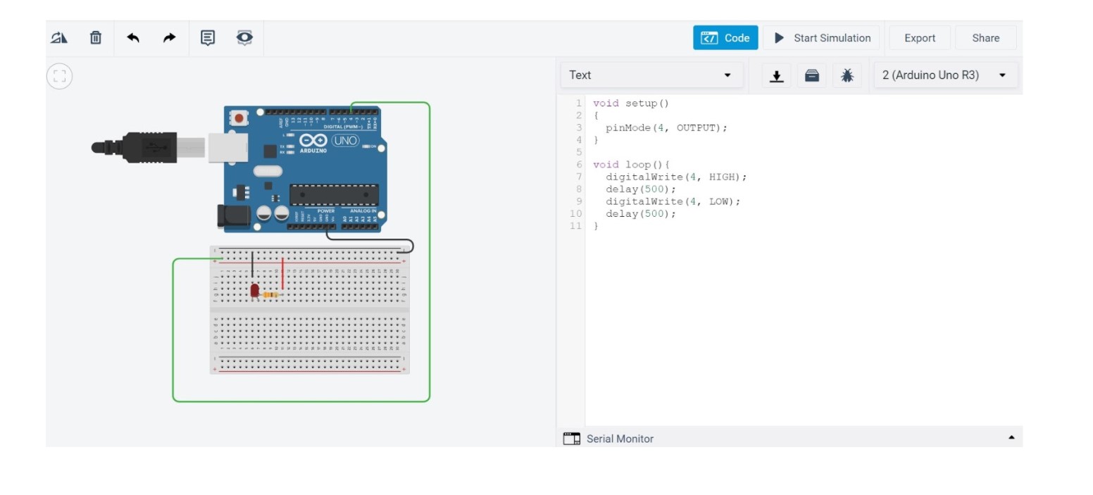
Let’s Take it Over to Tinker Circuit!
Tinker circuit is one of my favorite tools for testing and building simple electronics, as you start at a very basic level. Rather than troubleshooting an array of potential problems, you can work spirally by first focussing on “is the circuitry correct?” and “why isn’t the code working as intended,” rather more arbitrary issues encountered, such as one of you jumper wires not working for some reason. I wanted to start off just with a blinking LED light initially, as that is virtually the simplest demonstration there is in physical computing. Here’s the wiring for the simple blinking LED and the C++ code. Next, I needed to move over to the Arduino IED and upload to the ATtiny 412 chip itself with C++.