5. Electronics production
During this week’s assignment, our objectives were centered around using the CNC Mill, which we were asked to create an in circuit programmer. Using a bantam mill, we first milled and soldered a simple blinky board and then the programmer. Throughout this week I encountered an amalgam of issues from difficulty soldering, lack of access to components, milling trouble, and uploading the program to the board itself; nevertheless I learned about troubleshooting using multimeters and analyzing soldering jobs, as well as how to mill custom pcb boards.
I. Blinky Board
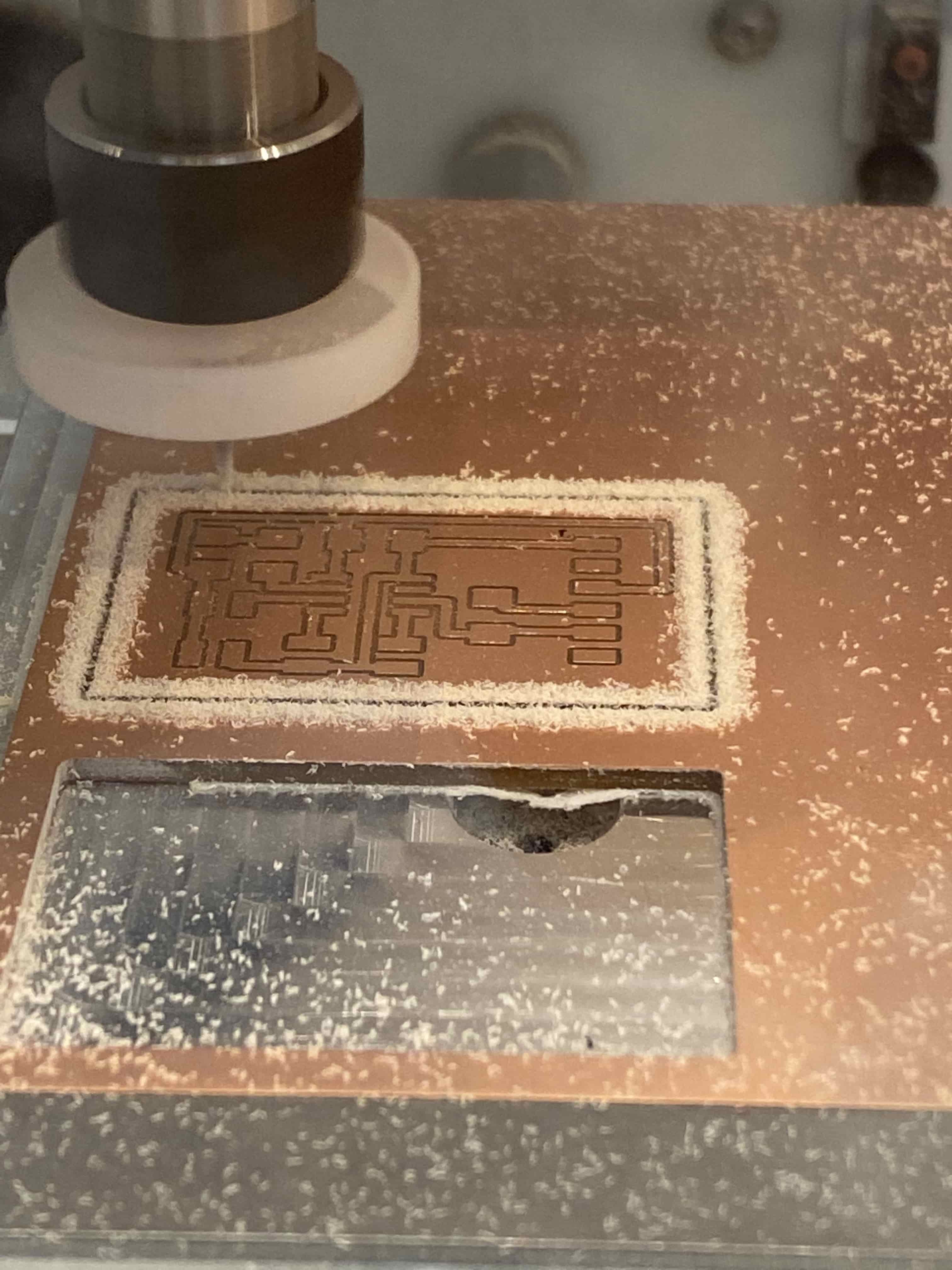
(1) Milling
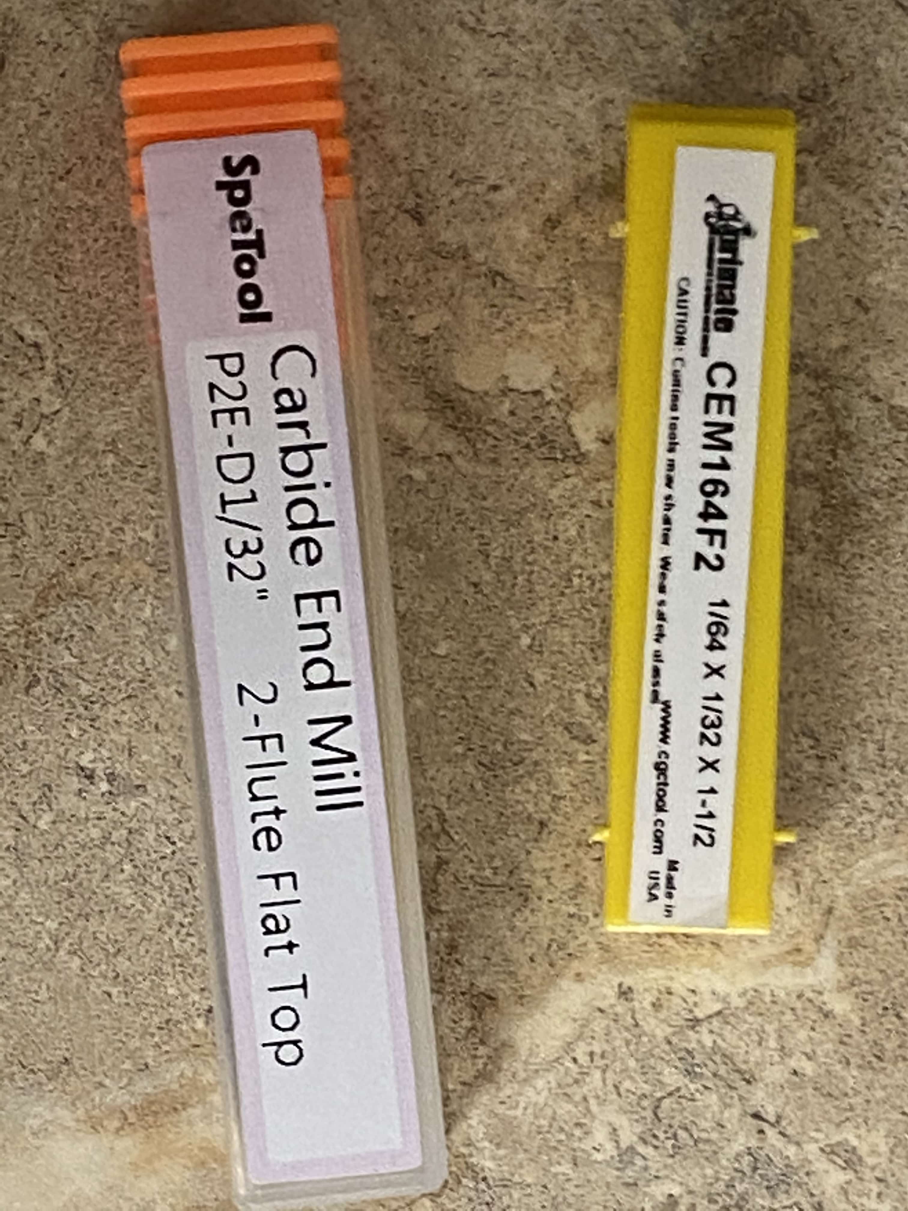
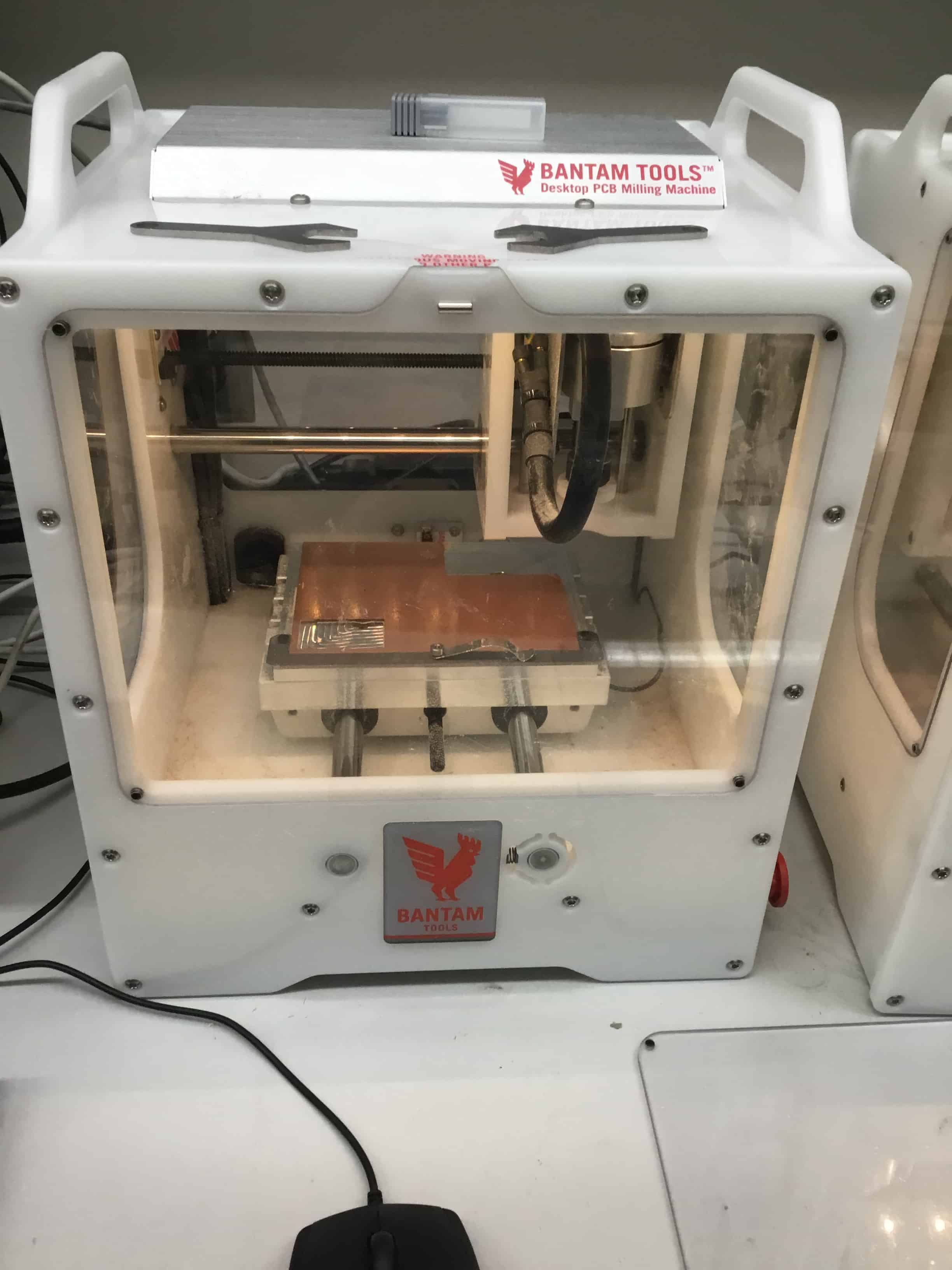
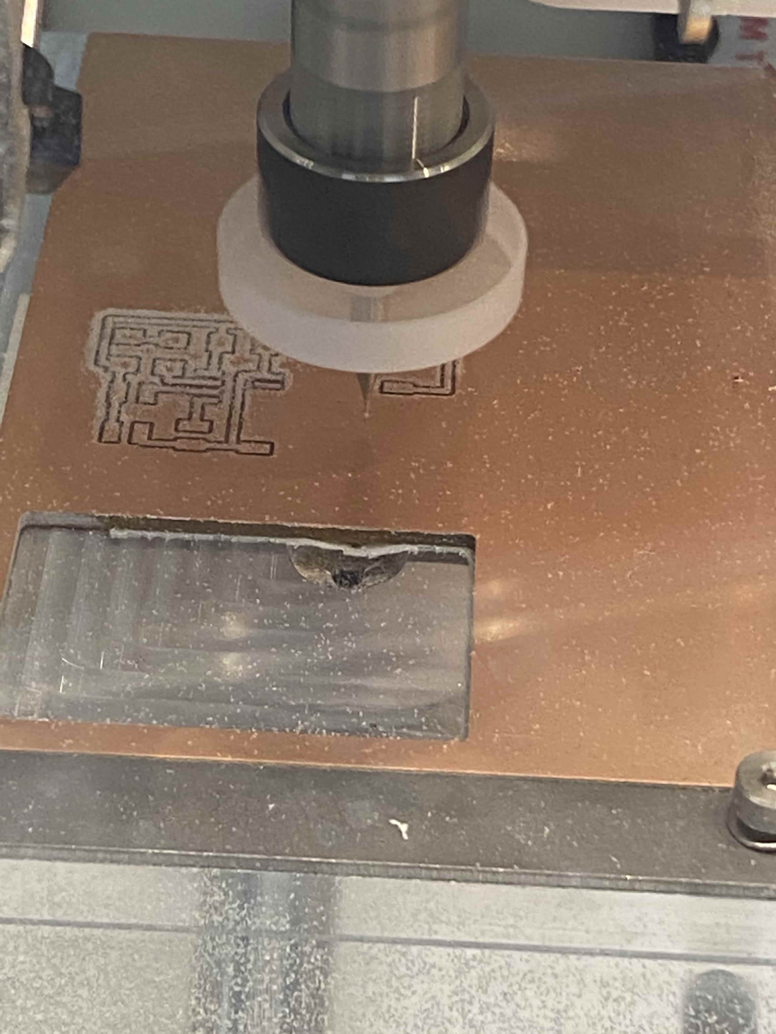
The first step of creating the blinky board was to mill it using the Bantam Mills in our Fab Lab with the Bantan Tool software. Over the course of this aspect of the assignment, I milled four separate Blinky Boards, so I was able to use different methods of milling. (1) On the machine, first I ensured that the mill had my desired bit; I used either a .005” engraving bit, a 1/32” flat end mill bit, or a 1/64” flat end mill bit. To install the bit, I unscrewed the cap with a wrench and then changed the bit out. We also used a fan on the bit to extend the lifespan of the flute by blowing away excess milled copper.

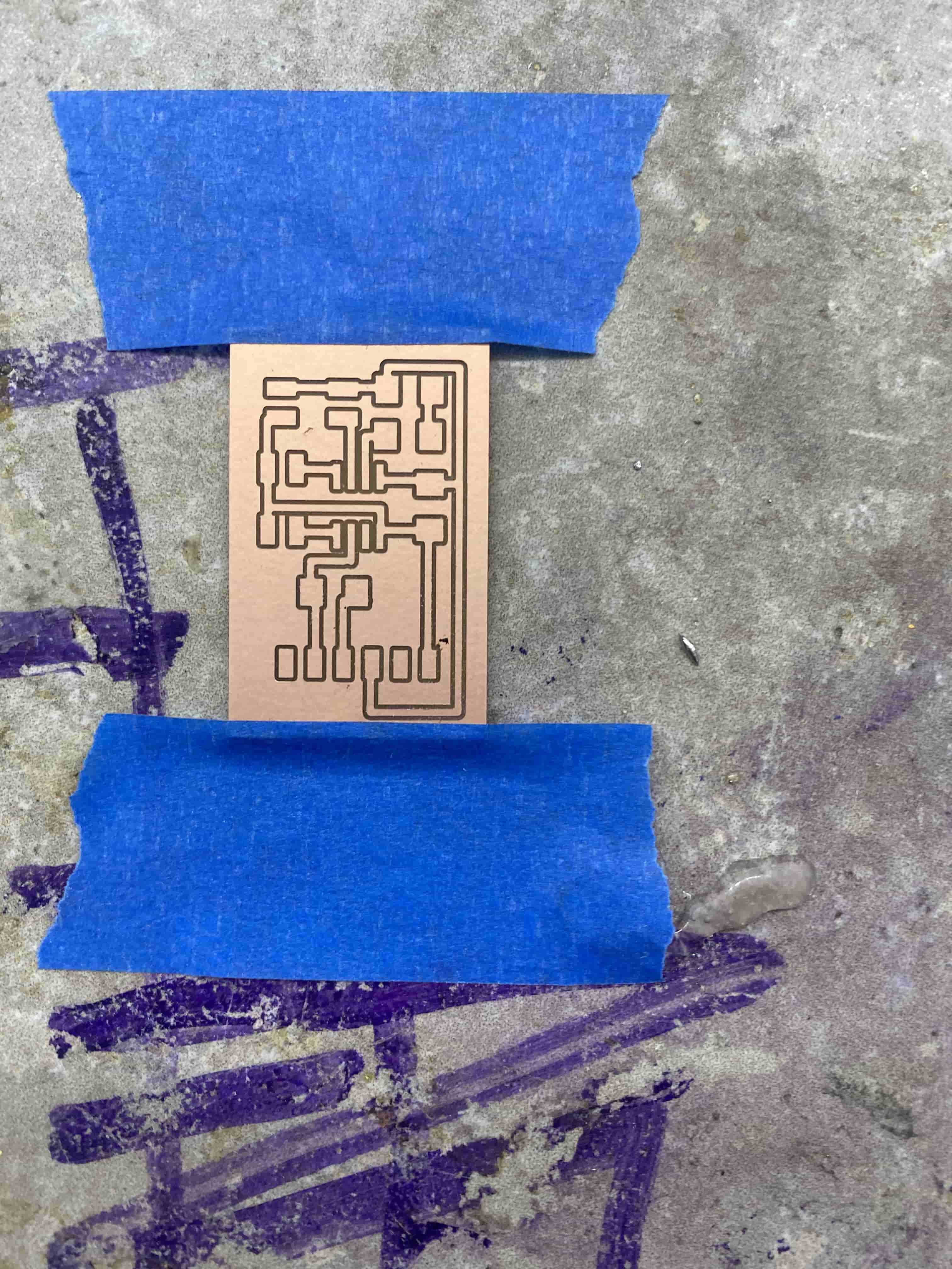
(2) Next, you import the file to mill, which I used an EagleCAD .bdr file type, and position the board in the software to where you wish to cut it. I used a Blinky Board, which was designed by Dr. Adam Harris and can act as a test for the in-circuit programmer. (3) Next, add double sided tape to the copper you plan to mill and attach the sheet to the mill work area. (4) Then, change the bit in the “locate tool” section and down below and follow the steps:
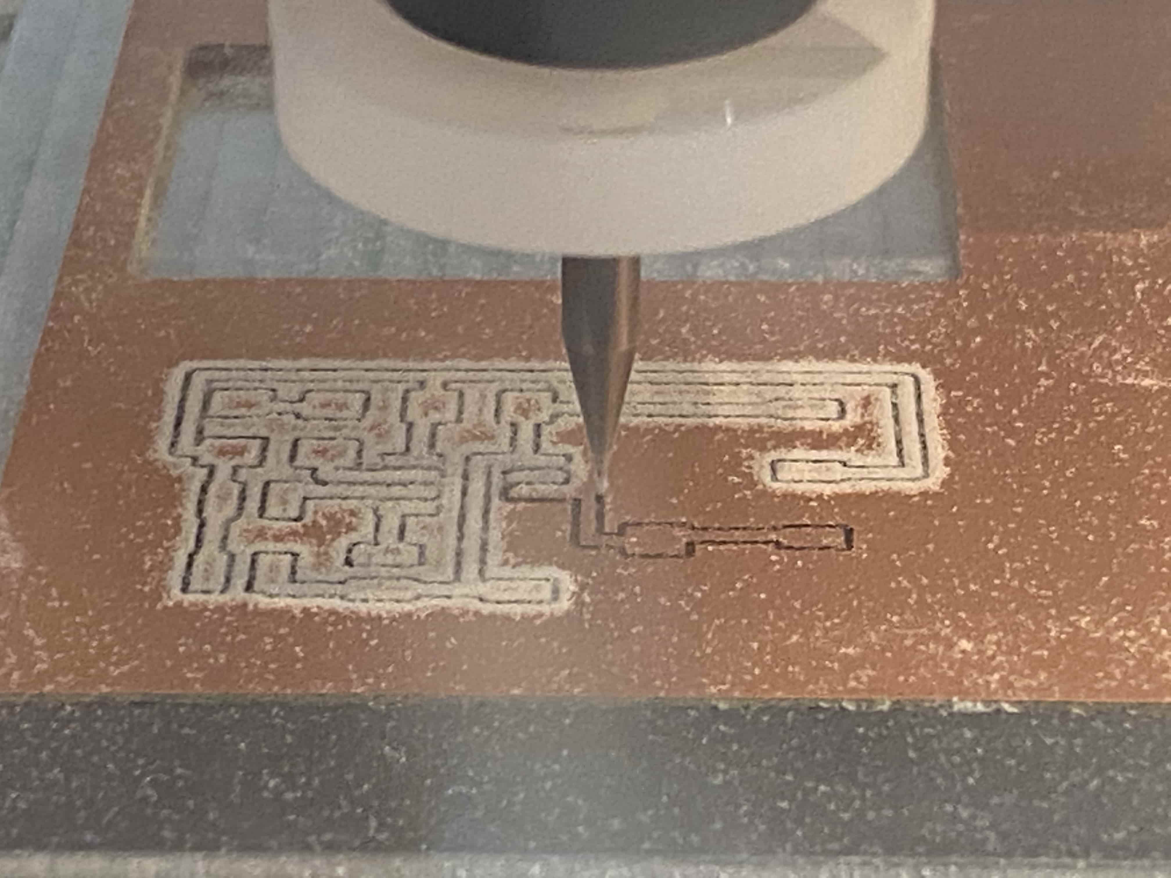
Blinky Board Milling Time Lapse Video
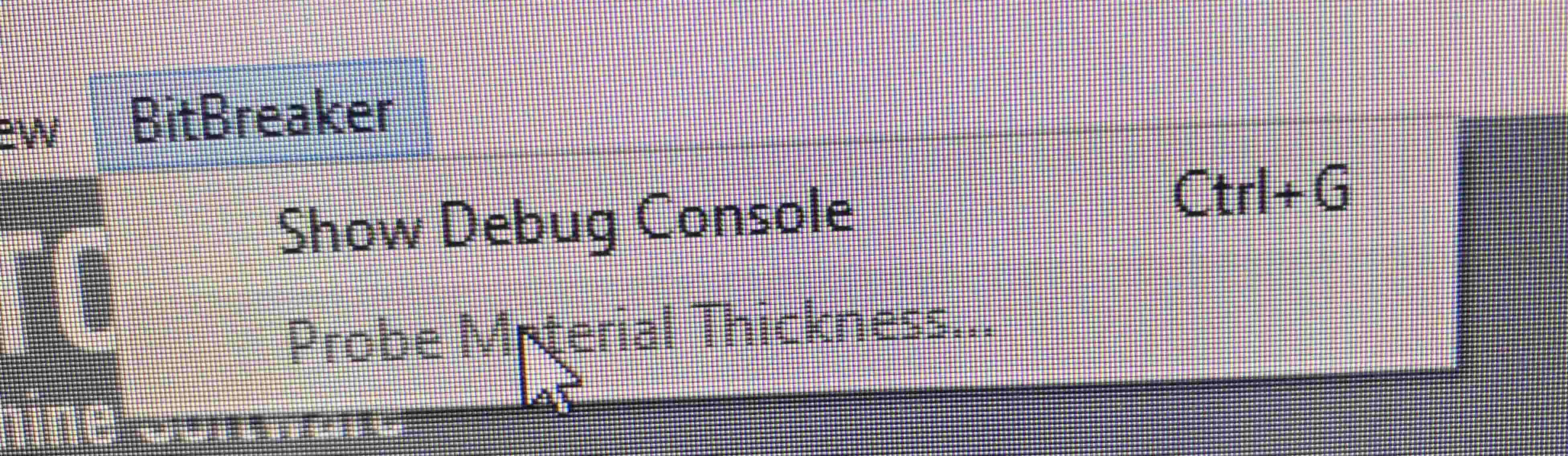
(5) Afterwards, ensure to probe the material thickness under the “BitBreaker” section, so the Bantam PCB Mill knows how far down to have the bit head. Also, before probing, attach the metal hand to the material to avoid breaking the bit.
Here is the workflow our class used created by Dr. Adam Harris:
Dr. Adam Harris’ Workflow
This is the simplest and easiest method for programming the new AtTiny chips used in Fab Academy.
Step 1: Download the EagleCAD and Arduino project files here. I recommend adding some trace clearance if possible.
Step 2: Solder all the components in place
Step 3: Use an ISP programmer to test this board by flashing the Blink.ino example in arduino by using Tools–> Upload using Programmer with the board set as Arduino Uno. If that works, you know that you can program the atmega. Something I did in addition is to manually wire up an LED on a breadboard, and changed the pin in the arduino code to pin 6. I wired this LED up to the UPDI pin on the programmer and programmed it just to make sure that the UPDI pin is not shorted out.
Step 4: You should get the LED to flash off the UPDI pin. Once you are sure that’s working and there are no communication issues move forward. If this doesn’t happen, you need to troubleshoot. Try to find any shorts on your board or under the traces.
Step 5: Install the megaTiny library in Arduino as described here. Here you can see my tips and perspective on the different two different methods of UPDI programming FabAcademy recommends so far.
Step 6: Use an ISP programmer to install this code to turn this board into a UPDI programmer from SpenceKonde called jtag2UPDI code (visit page, click “Code–> Download Zip” and then unzip this code to your computer and open the jtag2UPDI.ino project in arduino.)
Step 7: Once this is successful, you can cut the trace between jumper on the board (JP1). Congrats, you now have a UPDI programmer! Now you can use it
Step 8: Connect your target board. if you don’t have one yet, here’s a simple board I designed that uses an AtTiny412 with an LED and pins broken out for other input/output.
Step 9: Open the blink example and change the pin numbers to 5, change chip to Tools–>Chip–>AtTiny412, change programmer to Tools–>Programmer–> jtag2UPDI. change the com port if necessary.
Step 10: Upload the blink code to the target board by clicking “upload” or “upload with programmer” and you’re done!
Design: In Jan 2021 I came across the Faboulu board which was basically the same thing as my design but with the FTDI chip on the board. I downloaded this design, brought it into Fusion 360 (to test that workflow) and replaced the FTDI chip with a 6-pin header to be used with a Serial-UART dongle. We have like a hundred FTDI breakout boards in the lab, so this is a perfect solution.
Video link is here: https://www.youtube.com/watch?v=n4Poe0N_CSg
The Settings I used for Milling My 1st Board
| Tracing Bit | Trace Depth | Trace Clearance | Outline Bit |
|---|---|---|---|
| 1/64” Bit | .20mm | .25mm | 1/32” Bit |
While at this point, I thought I was done milling the pcb blinky board, due to several mistakes soldering, I would have to re-mill the board several more times, which is a testament to the idea that often in engineering, tasks can take much longer than expected because nothing works correctly the first time.
(2) Soldering
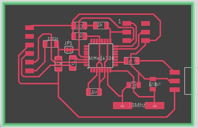
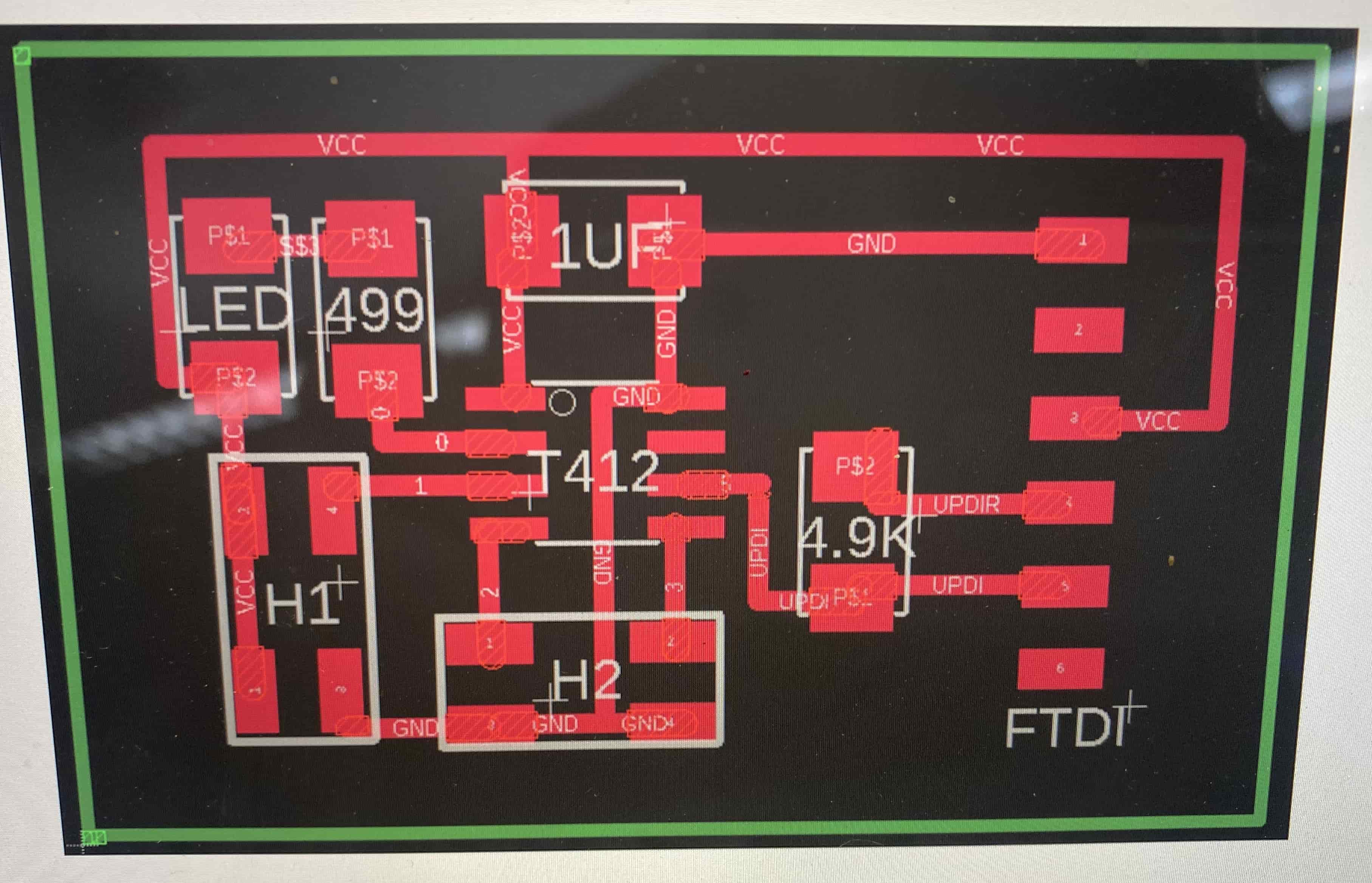 Above is the design of the PCB board that we milled and the components we used. One of the tricks I learned when soldering the board was that zero ohm resistors could be used as “bridges” or intersections, so milled paths can intersect each other.
Attempt #1
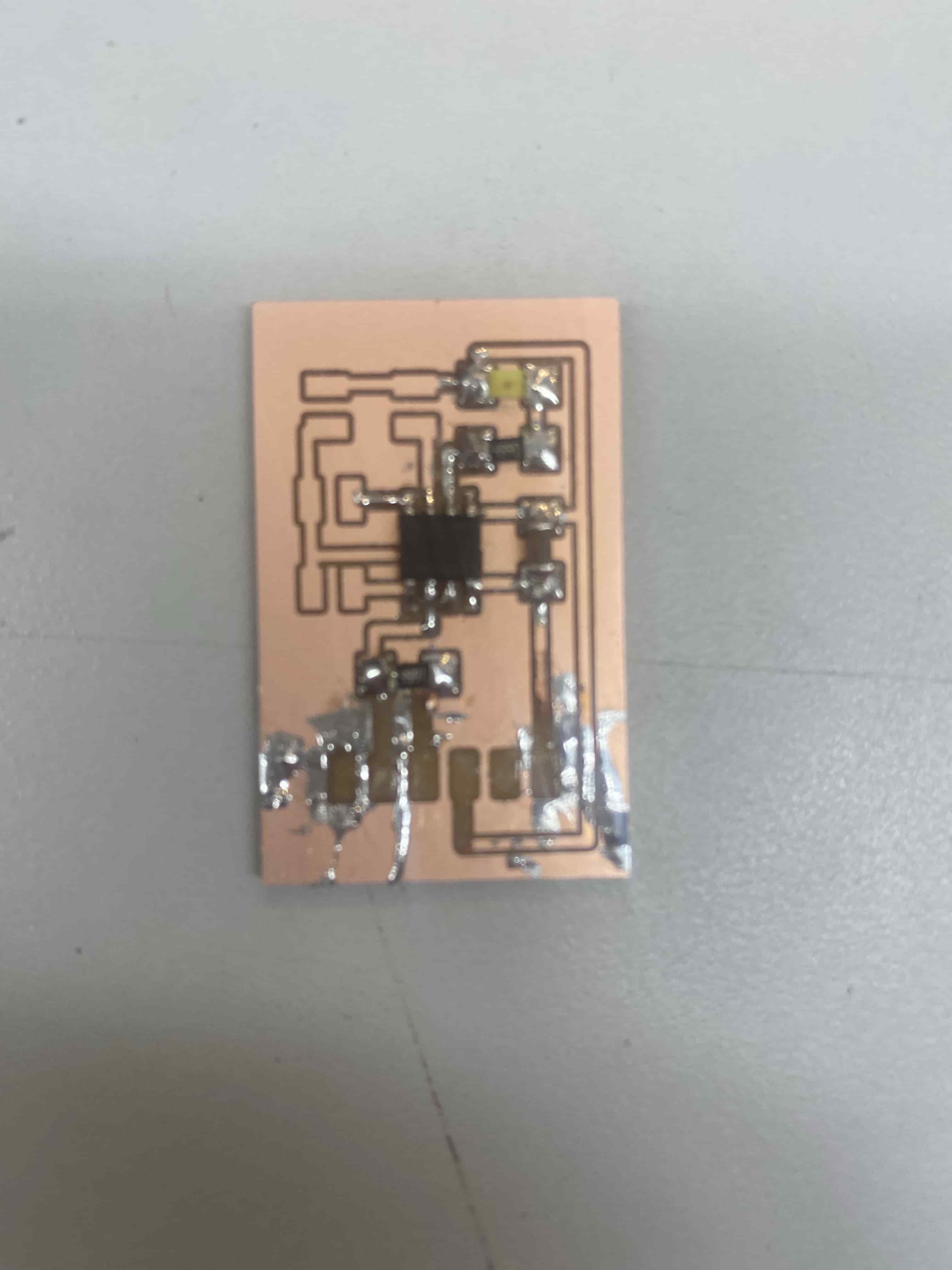
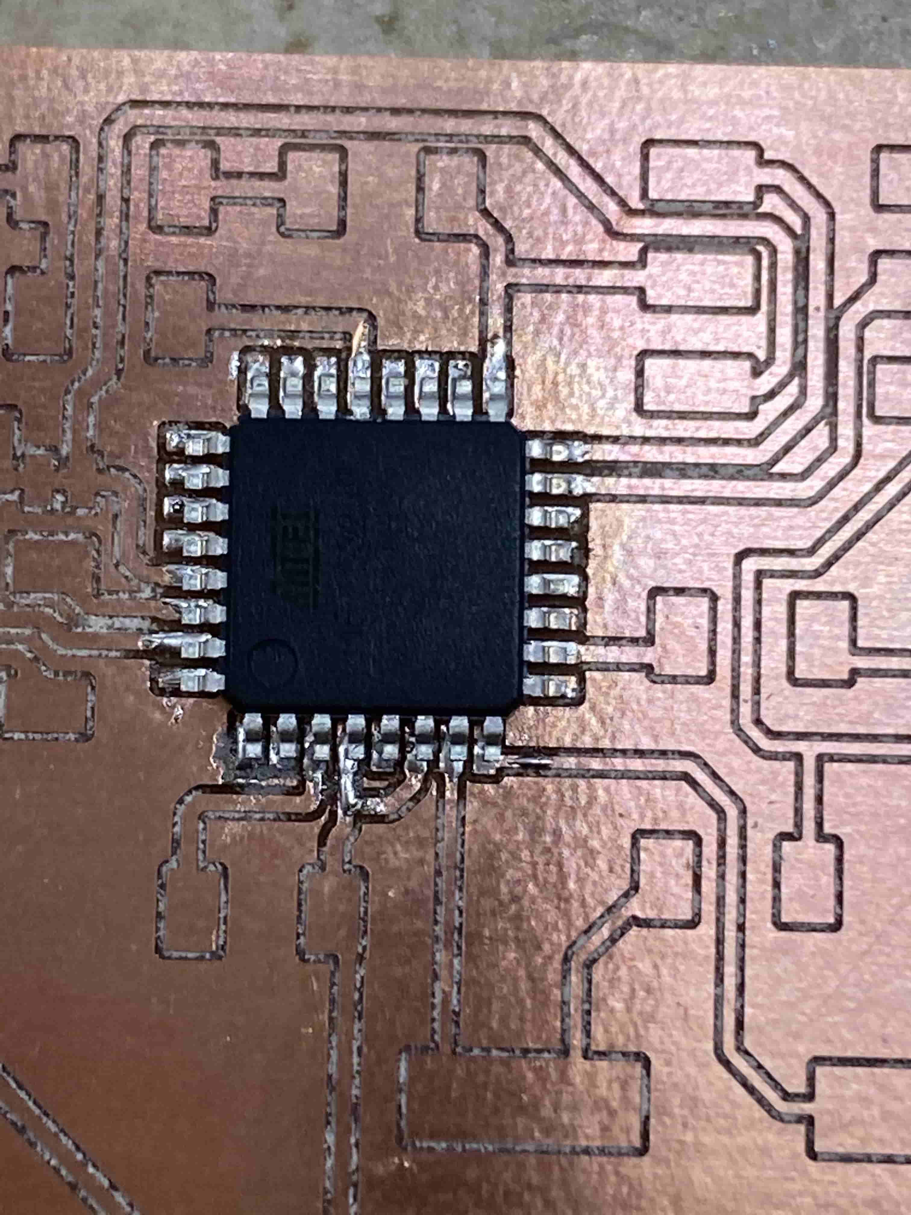
Over the course of soldering the boards, I created four in total. In each of them, I particularly struggled with solderingthe microcontroller without any bridges due to the close proximity between each leg of the chip. Additionally, I ripped several of the pads in the process further leading to me breaking the board; however in the end, I was able to get a working board.
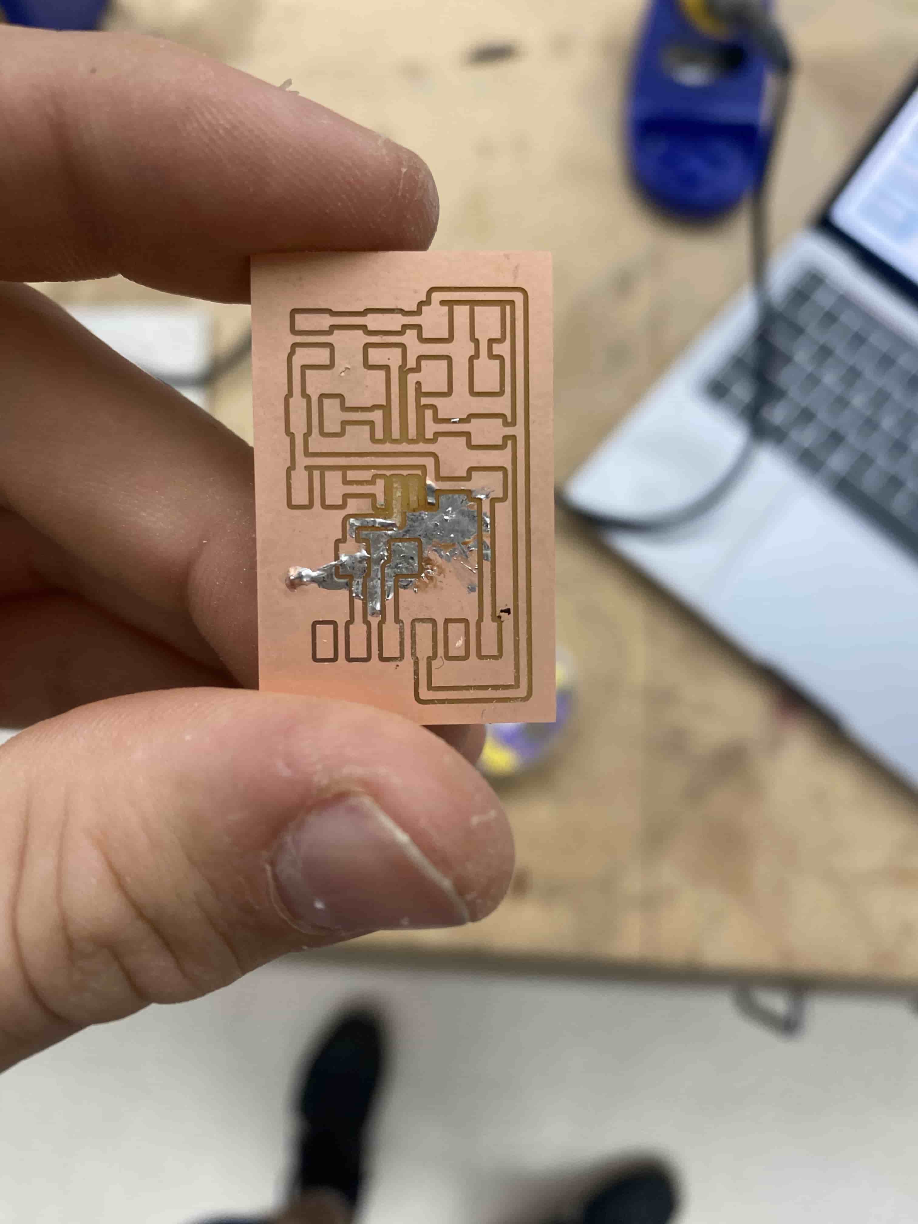
Final Board:
(3) Uploading the Code
Prior to testing the programmer board, we first wanted to ensure that it was working by using a simple blink test example on the board. During this step, I had to go back several times to clear up any solder bridges in my board to make sure it functions correctly; however, it worked as intended.
II. Programmer Board
(1) Milling
Milling the programmer board was similar to milling the Blinky Board, but with more pads and traces. Similarly, this process was the easier step, as I had already had experience milling several boards for the first one. Again I used a 1/32” flat end mill bit for the outline and a .005” engraving bit on our lab’s Bantan Mill machine using its software. I had issues milling the boards each time.
(2) Soldering
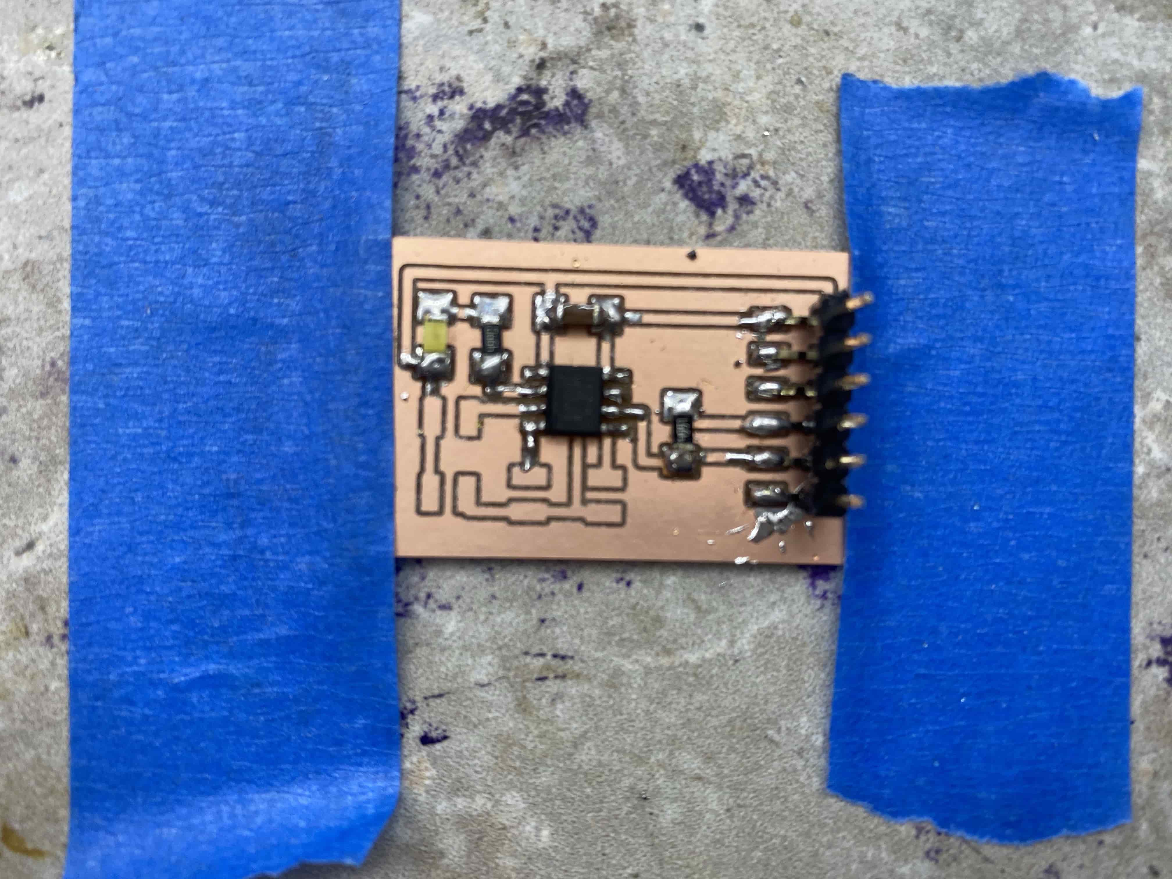
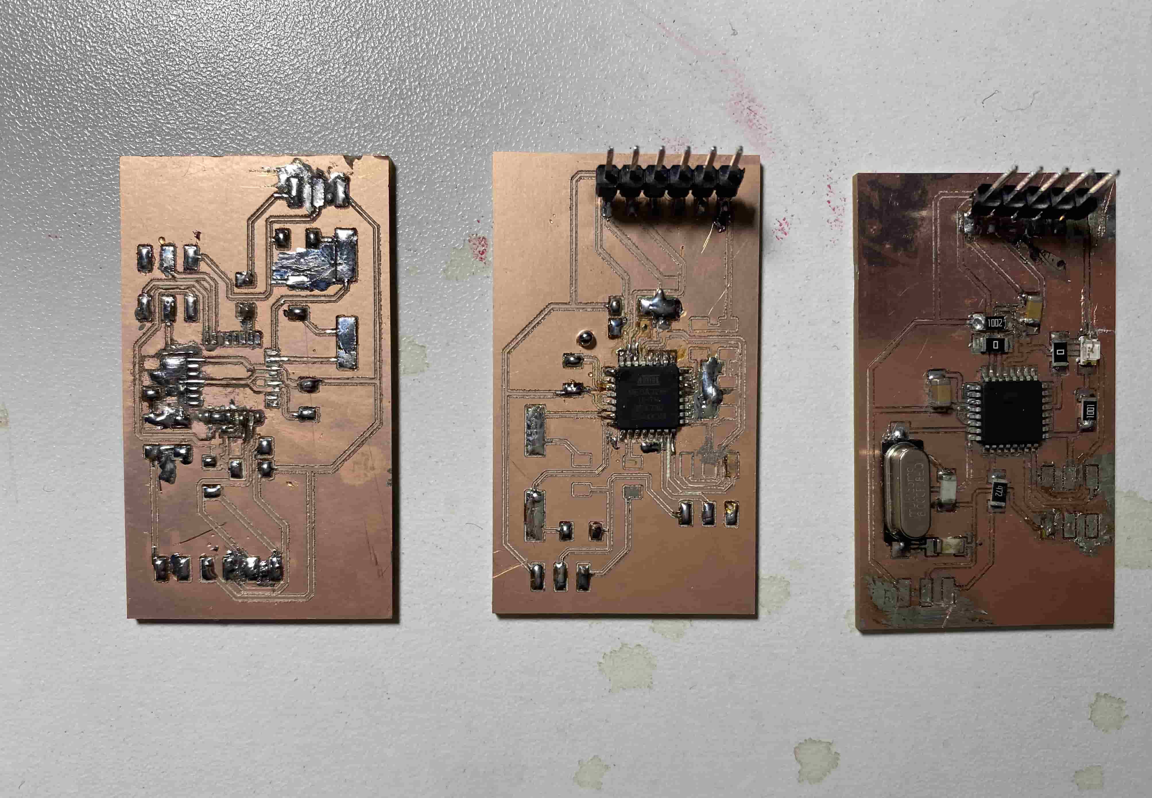
Similar to the first step, In struggle successfully soldering the board without any bridges or major issues. Soldering the microcontroller was particularly difficult for me ndie to the number of pins on the board, but solder paste helped me in adding a small amount of solder to each pad without having any solder bridges. Additionally, the LED caused some distress, as the multimeter test to see which side was the positive and negative only sometimes functioned. Here are three boards I made in this step of creating the programmer board
III. Additional Links & Downloads:
- Blinky Board Files
- Uploading Program to Blinky Board Referenced Website
- Our Instructor’s (Mr. Dubick) Background Information Video on Programmers