Embedded Programming Architecture Types
This week’s assignment was to learn about and analyze different workflows for diferent types of architectures. As we had only programmed microcontrollers with variants of C thus far in Fab Academy, we decided to configure and program an LED to blink on a Raspberry Pi 4 and a Raspberry Pi Pico in order to investigate the programming and uploading process using different form factor boards and a different language from what we are used to.
Raspberry Pi
The first type of architecture we wanted to try was Raspberry Pi.
PI Setup
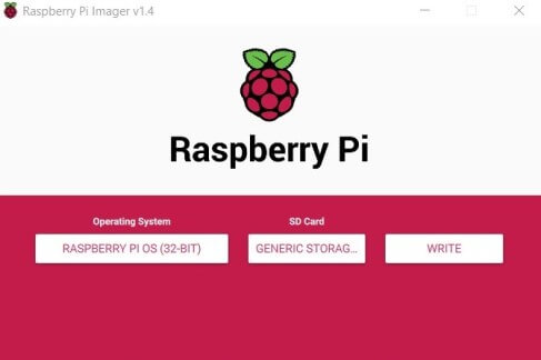
As we could not find a Pi that already had an operating system installed and configured, we decided to boot a fresh copy of Raspbian on a new RPi 4 in order to take advantage of the faster write speeds offered by the latest variant of the microcomputer. Nevertheless, we were still booting from a microSD card, which are not known for celeritous read/write speeds. As such, the entire installation process of the lite version of Raspbian took upwards of 30 minutes to fully complete.
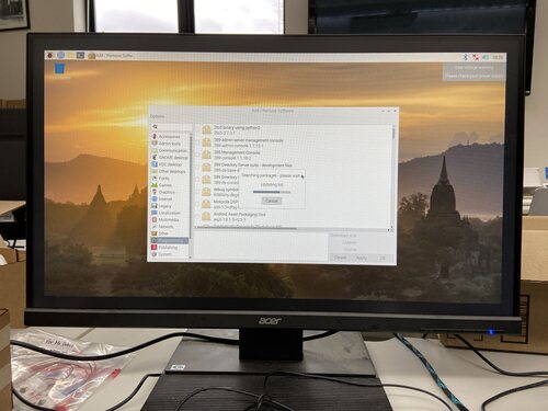
After booting a fresh OS on the Pi, we verified that all of the modules, programs, and libraries that we would need to make the LED blink were included in the base installation of Raspian. After installing Python 3.8 we were ready to begin wiring the LED to the Pi’s GPIO array.
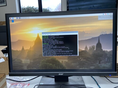

After downloading the necessary programs, we began researching the pinout of the GPIO array on the rPi 4 in order to know how to wire our LED to properly address it via a python script. We used this guide as a reference for the wiring of our LED to our rPI 4.
GPIO Control
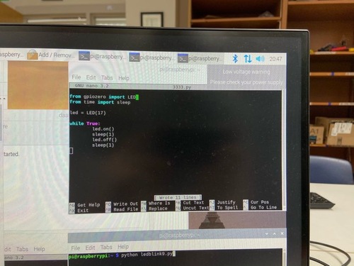
We decided to write the python using an internal text-editor, nano, that is included in the base installation of most Linux distros, including base installations of Ubunto and Debian, that can be opened with the command ‘sudo nano filename‘ and executed by simply typing the filename into an active Linux shell. This method does not require an external IDE that must be installed by a user, and due to the simplicity of the code that was necessary for our LED to blink, it made total sense to utilize this basic text editor rather than using alternative environments like Thonny or IDLE.
After repeated troubleshooting with very simple codes, we finally found 2 possible reasons the LED was not blinking. The first thing we found was that instead of using a 330 ᘯ resistor, we were accidentally using a 1,000,000 ᘯ resistor. While the LED would technically still turn on, it would be so dim that the change would not be visible to humans, which defeated the purpose of making the LED blink. We ultimately discovered that the 1,000,000 ᘯ resistors were mixed with the 330 ᘯ resistors in our lab, and an incorrect resistor had been selected from the box. After swapping the 1,000,000 ᘯ for a 330 ᘯ resistor that we verified did have the correct resistance value with a multimeter, the LED still did not blink.
After switching the resistor proved futile in resolving our problem, we postulated that the issue likely was caused by a faulty LED. To eliminate verify the state of the LED that we were using, we connected it directly to VCC and GND on the rPI, with a 330 ᘯ resistor connected between VCC on the LED and the Pi, and discovered that we were using a faulty LED as it still was not illuminated. After identifying this potential cause of the issue, we swapped the LED to an LED that we verified was working correctly with a multimeter, and executed our python script with the new connection made. After running the code, the LED turned on and toggled its state each second.
The following code is what is running on the Pi in the final video of our LED blinking on the Raspberry Pi 4.
from gpiozero import LED
from time import sleep

led = LED(17) #GPIO 17
thisCodeWorks = True

while thisCodeWorks:
    led.on()
    sleep(1)
    led.off()
    sleep(1)
LED Blink with Raspberry Pi Pico
The Raspberry Pi Pico is a relatively new proprietary microcontroller product that is manufactured by Raspberry Pi, which is an incredibly economical option compared to the Arduino class of boards which tend to cost 2-3x as much for a comparable product. The Pico also has considerably superior technical specifications to the ATMega328P microcontroller that is found on most consumer-grade Arduino Products. The Pico has a clock speed of 133MHz while the 328P runs at just 16MHz. Additionally, the Pico features 30 GPIO pins, while the 328P features 26. As nobody in our group had employed this compelling new technology prior to this week, it was incredibly interesting to delve into the world of Raspberry Pi’s first proprietary microcontroller that is an incredibly promising rival to the Arduino series of products, which will hopefully incite speedier proliferation from each side in the coming years. We decided to do the same thing that we did with the rPI 4, blinking an LED via GPIO headers, in order to compare the processes for writing to the LED using the different protocol that is required by each board.
Configuring rPi Pico
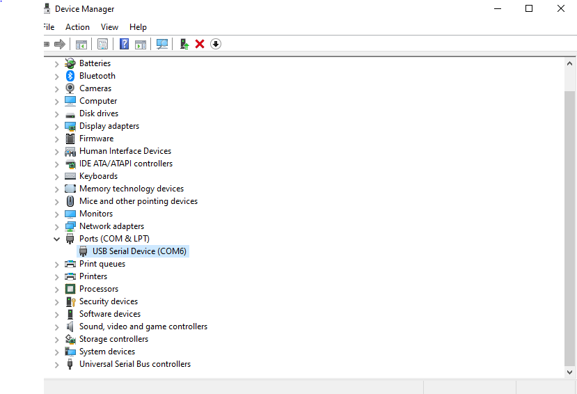
As the Raspberry Pi Pico is a standalone microcontroller board, it requires a connection to a PC, preferably a machine running Windows 7, 8, or 10, and some software on the machine. The board also uses a different variant of Python that is converted into code that is readable by the microcontroller, which is called MicroPython. First, we needed to install PuTTy, which would allow us to write directly to the microcontroller without needing to perform uploads each time we wanted to put new code onto the Pico. Configuring the Pico requires a relatively straightforward process, but as the most optimal resetting process requires destroying the USB connection between the board and master machine, it can become a quite tedious process during phases that require repeated troubleshooting. Using PuTTy, users must search for the Pico in the ‘Device Manager’ Windows tab and manually select the specific port of the device within PuTTy.
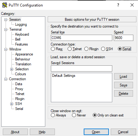
After locating the port address of the Pico, there are several fields that need to be filled out within PuTTy before a successful connection can be made to the board. The proper values for each field are displayed below. The next step is to open a serial connection between the PC and the Pico and begin the transcription of code in the console that is opened.
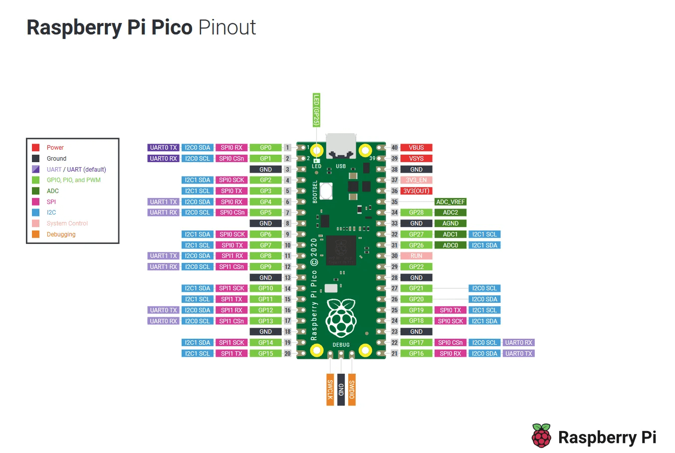
Wiring the LED to the Pico
While the connections on all other Raspberry Pi variants exist soley betwene the Raspberry Pi and GPIO devices, the Raspberry Pi Pico requires a USB connection to a PC in order to receive uploads. The GPIO connections to the microcontroller were made using the schematic found below. We first decided to make the onboard LED blink because it does not allow for errors to be made in the actually addressing of the pins, and would give us a better idea of what we were doing right so we could then apply that knowledge to the blinking of an external LED without questioning our ability to make any LED blink with the Pico.
Prog(r)am(m)ing
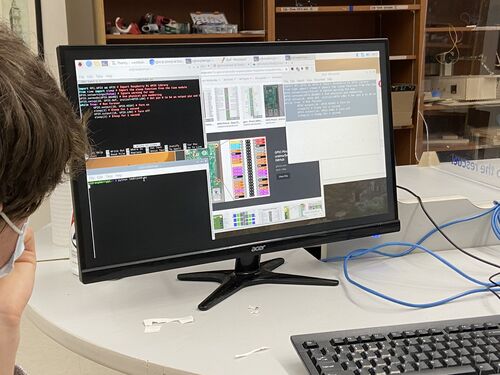
After opening a serial connection to the Pico using PuTTy, MicroPython code can be transcribed in the console line by line and is directly injected into the board. This is incredibly useful for rapid-prototyping, though a serial connection must be closed in order to restart; however, there could be an integrated restart feature that we are unaware of.
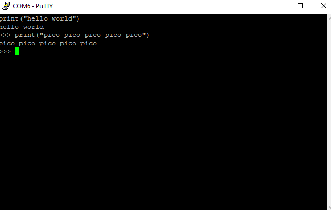
We first tested the MicroPython shell with a brief print statement. After verifying that the shell was working correctly, we began injecting MicroPython code into the Pico in order to blink the external LED that we attached to pin 0 on the device.
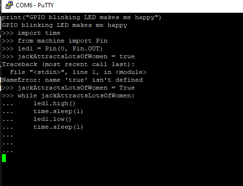
print("GPIO blinking LED makes me happy")
import time
from machine import Pin
led1 = Pin(0, Pin.OUT)
jackAttractsLotsOfWomen = True
while jackAttractsLotsOfWomen:
    led1.high()
    time.sleep(1)
    led1.low()
    time.sleep(1)
Conclusion
After successfully uploading a code that effectively accomplished an identical task using two vastly disparate workflows for two different boards, our group reflected on the stark differences that exist between the Raspberry Pi 4 and Raspberry Pi Pico. Firstly, we felt that our task was not intensive enough for the performance differences between the two devices to be noticeable in their ability to complete the task, meaning that the Pico made far more financial sense as it costs roughly 10% that of its mircocomputer counterpart. We found that the rPi 4 made rapid re-iteration significantly easier, as the Pico requires a multi-step process in order to be ready to receive fresh code injections via PuTTy. Ultimately, our group work for embedded programming week in comparing similar tasks on two different architectures provided an intriguing glimpse into the processes outside of the Arduino IDE and Atmel ecosystem, which many of us hope to utilize in our final projects as well as in future endeavors outside of Fab Academy.