Design rules for 3D-printing
This week, we were tasked with testing the design rules for the 3D printers we will use. We completed these tests on our Ender 3 3D printers we all build to take home during our Computer-Aided Design week.
Terms and Definitions
| Term | Definition | |
|---|---|---|
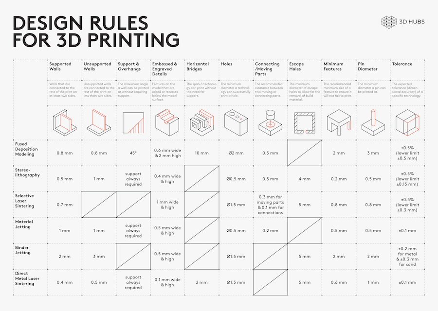
| Overhang | 3D print overhangs are geometric shapes in a 3D model that extends outwards and beyond the previous layer. Overhangs have no direct support on it so it is difficult to be printed. Nonetheless, there are overhangs that are tolerable. These are 3D print overhangs with as much as 45ᵒ angle. But, if it exceeds this number, then issues such as droopy filament strands may be encountered. Possible solutions to these problems is the usage of supports. The drawbacks of supports include increased print time and messy supports that will have to be cleaned up after the print. In order to reduce errors while printing overhangs it is recommended to avoid angles that exceed 45 degrees | Source |
| Bridges | In 3D printing, bridges that are 90ᵒ surfaces are supported on both ends and links two raised points. Bridges present similar printing problems as overhangs. For bridges, the tension on both ends of the string keeps it from collapsing or crumpling. In other words, if the length of the bridge is shorter, it has a greater chance to succeed and not collapse. On the other hand, if the bridge is longer, it has a greater chance to experience structural stress. Nevertheless, this issue is relatively easy to be fixed. Bridging is when the printer must print a flat, horizontal part of the model mid air. Although using a support structure for such a part could be a solution, it often works to just bridge the gap without using support. The Ultimaker will have to drag lines of plastic between already printed parts, in a way that the plastic won’t fall down when being printed. This page explains which settings are recommended for the best bridging results. | Source |
| Clearance | Once you discover the tolerance of your 3D printer you can design parts with proper clearance Parts should be created with enough space between them to account for potential dimensional deviations. Poor understanding of your 3D printer’s tolerances can cause parts to fit poorly or support structures to fully adhere to your prints.In 3D printing, like any other manufacturing process, machines have specific tolerances. This means that prints may slightly deviate from the actual dimensions. A tighter tolerance indicates consistently higher dimensional accuracy. This is similar to the join clearance measurement for laser cutters. | Source |
| Infill | 3D printed parts are typically not produced with a solid interior. Instead, the printing process uses a crosshatch or other pattern for interior surfaces. This greatly reduces cost due to reduced material usage and print time, while moderately reducing strength. The density of this pattern is referred to as the infill percentage.0-20%: Non-functional parts: For pieces that are not functional or do not need to withstand force, such as a display model or presentation prototypes, 10-20% infill is sufficient. In some cases, no infill is a viable option if there are no large flat surfaces on the top of the print. If there are large flat surfaces on the top of the print, some infill is needed to support those surfaces. 20-40%: Light-use parts: For functional parts which will undergo some force, a moderate level of infill provides nearly the same strength as a solid part at a reduced cost. 40-100% Heavy-use parts: If your parts must withstand significant forces, or strength is the most important factor above cost, a higher infill percentage is the best choice. However, increasing infill percentage beyond 60% has diminishing returns on strength.The price difference between higher and lower infill settings can vary greatly depending on the geometry of the model. Models with more interior volume will see a significant impact to the cost from changes in infill percentage, whereas thinner parts may see no impact. Print speed is another factor to consider when choosing an infill percentage for a 3D print. A higher infill percentage will result in a longer print time, especially on models with a large interior volume. | Soucre |
| Surface Finish | A 3D printed part is still a incomplete product after it comes out from a 3D printer. Thus, it will at least require some amount of post-processing particularly in aesthetic terms and functionality. This is where surface finishing comes in. It is a technique that turns a raw 3D printed part into a finished product. This could include all sorts of processes, but mainly consists of removing any supports. | Soucre |
Printing
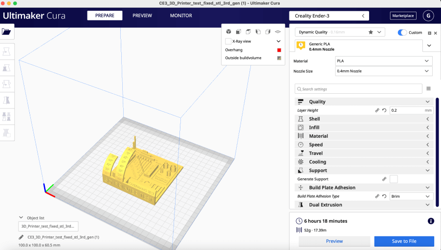
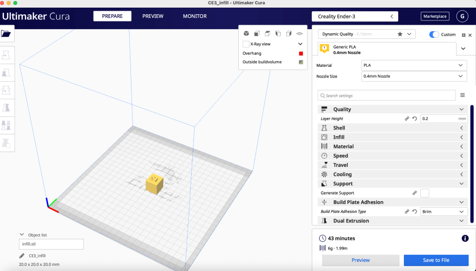
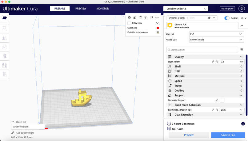
To test the design rules discussed above on our Ender 3’s, we used a series of test prints that allowed us to view how our printers handled controlled adjustments to changes in different settings. All of the models used in our testing can be found on the downloads link on this page, and these tests range from analyzing the impact of modifying overhangs, conduct bridging & surface finish tests, a clearance test, a test for viewing different infill settings, and a final test print of an incredibly demanding model of a boat, 3D Benchy. We used Ulitmaker Cura to slice these files into machine-readable gcode, as it offers a profile for the Ender 3 Pro upon downloading the software and offers many additional useful features. For each of the models that we tested, we used the ‘Creality Ender 3’ machine profile that is included in the current stable release of Cura. This profile includes the dimensions of our machine and various presets, though these settings are poorly optimized and often generate low-quality prints. In addition to that, we used the ‘generic PLA’ material profile while slicing all of our tests, as we planned to only utilize PLA filament during the printing of the test models. While Cura does offer an option to generate support structures and allows users to specify the integrity of the supports, only our test for printer clearance required the use of supports as the other models were capable of standing on their own during printing. Each test we conducted utilized the same setting for layerheight, which we left as the default value of 0.2mm. Oftentimes, a layer height of 0.2mm does not yield high quality prints, though we managed to optimize the settings to an extent that our prints were certainly acceptable in terms of their quality given the relatively fast print speed that we selected for each print. After applying our settings, three of the four tests were immediately ready to print; however, the duration of the gcode generation for the infill cube test file was significantly longer than the other files. On this cube, we shut off the top surface of the cube by editing the number of top layers to be printed within Cura through the ‘shell’ tab offered within the software. under the Shell tab in cura. This would leave the cube incomplete, allowing us to see the infill and assess its quality. Then, we generated four separate .gcode files of this cube, changing the infill percentage for each one, ranging from 0% to 15% to 50% and finally to a solid 100% infill print.
![]()
After generating the gcode for each test print, we embarked on the actual printing process. Our print beds were already leveled from previous prints, so we were able to skip this step and begin by loading the gcode files onto our Ender 3’s. As our printers, with the exception of Teddy Warner’s printer that is networked because he knows how to use Octoprint, are not networked, we needed to load the gcode onto the printer via MicroSD. By navigating the UI of the Ender 3 via the dial/push knob situated below the screen, we navigated to the ‘print from SD’ option and selected appropriate files for each respective test. The machine then conducted the rest of the process by reading the gcode that we generated for each model.
Test Results
Overall, we observed impressive results from the various test prints that we conducted on our personal printers. Our lab previously offered subpar Lulzbot 3D Printers which do not print in the professional quality that every self-respecting maker aspires. As each student in Fab Academy node received a personal Ender 3 before the program began, we wanted to optimize the settings on these printers to see how high of quality we could produce using these cost-efficient but uncompromisingly powerful machines. The accuracy of the Ender 3’s was astounding compared to that of the far more expensive Lulzbot Taz machines that we previously had in our Fab Lab. The culpability for the drastic increase in quality of the Ender 3 can primarily be attributed to the smaller nozzle on the Ender 3 compared to that of Lulzbot’s line of flagship printers, allowing for greater accuracy of filament placement. While the Lulzbots use 0.5mm nozzles, our Ender 3’s feature 0.4mm nozzles, which allowed for a drastic increase in the quality of our test prints.
Experiences with overhangs, bridging & surface finishes
In the overhang, bridge, and surface tests, we again observed impressive results.. The overhang performance performed impressively, reaching 70 degrees before our print quality deteriorated. Since the overhang test went well, the bridging test also did pretty well. On the other hand, the surface test did not yield impressive results. It was apparent that the nozzle left behind lines on previous layers due to scraping. As a result, the final print was left with a checker board pattern that was left behind, leaving the infill visible due to the lack of a solid, smooth surface on the final layer of the print.
Infill
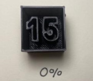
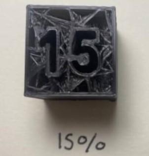
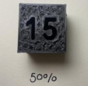
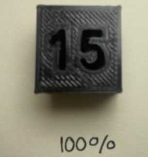
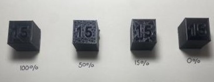
The next key step in characterizing the Creality Ender 3 printer was the infill test. The term infill refers to the amount of material that fills in something; in the case of 3d printing, infill means how much PLA lies in between the walls of the print. In this case, we used four variants of 100%, 50%, 15%, and 0% to visually demonstrate the different infills. Typically, one does not use a 100% infill, as it uses more PLA and it takes substantially longer; however the infill of a 3d print depends on the intended application of it. For example, if someone wants a stronger print with PLA and does not mind the slight additional print time and weight, then they may consider using a higher percentage infill. On the contrary, if someone aims for a more lightweight print or they just want to print something more quickly, a lower infill percentile could be used. In our test, the 100% infill of a cube smaller than an inch by inch, it took over an 1 hour and 30 minutes to print at regular speed on the Creality Ender 3. As the infill decreased though, the print time decreased exponentially to under 20 minutes for the 15% infill. The 0% infill is not very practical for most desgns, but it was included in the test to demonstrate what no infill would look like. There are obviously other factors which factor into print time, such as the other settings expressed in this assignment, but infill should be considered for each print to optimize each print produced.
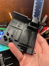
3D Benchy Test Print
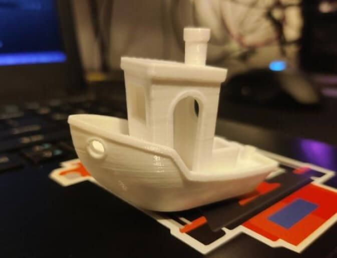
The 3D Benchy test is the ultimate test for any 3d printer as it challenges every capability of a machine. On stock settings, our Ender 3’s performed well but the quality increased tenfold following our optimization of various settings. The steep overhangs and bridges featured in this model were not droopy and retained their shapes excellently. Following the print, the filament did not suffer from stringing or other flaws that undermine the aesthetic appeal of a print. The 3D Benchy file, printed from a sub $300 machine produced an archetypal professional model worthy of occupying a central display in any esteemed art gallery. As the settings on our printers were optimized to maximize efficiency as well, existing ghosting that occurred on lesser speed settings exacerbated pre-existing problems with ghosting, though this was not a significant problem. The most impressive achievement of our budget printers during this demanding test was their ability to display the preponderance of minute details featured on this model to an impressive extent. For example, the chimney atop the structure retained its detail and quality following the optimization of the print speed and various other settings. Additionally, the sleek sides of the boat which would be expected to be featured on any seaworthy vessel were included in the final print, something that was surprising given the extent by which we increased various settings when optimizing. Ultimately, the incredible quality of our 3D Benchy test is a physical testament to the quality of the Ender 3 and its merit as a budget-friendly but uncompromisingly competent machine.
Downloads
Click here to get access to our test files.