Characterize the PCB design process
In this week’s group assignment, we were asked to characterize the design rules for our lab’s PCB production process: document feeds, speeds, plunge rate, depth of cut (traces and outline), and tooling. We found these values on one of our lab’s Bantam PCB Milling Machines.
Intro to PCB milling
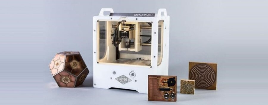
Along with all of our personal electronics production assignments for this week, our group was tasked with the second group assignment of the year, to characterize the design rules for our labs PCB production process, learning the document feeds, speeds, plunge rate, depth of cut (traces and outline) and tooling. Our lab has access to four Bantam PCB Mill, formerly know as OtherMill before a name change. These PCB milling machines were entirely new to all of us, and before starting with this week’s assignments two of our instructors, Mr. Tom Dubick and Dr. David Taylor covered the interface and workflow for the milling machines. We used their guidance along with our lab’s milling workflow to work through this week’s assignments. This workflow is attached as a document below.
Definitions
| Term | Definition | Source | |
|---|---|---|---|
| Feed | The feed rate represents how fast the machine will move the router bit through the material when cutting and is critical to have the appropriate feed rate for a clean cut. | Source | |
| Speed | The Spindle speed in rotations per minute (RPM) should be set to a value that is appropriate for the tool being used and the material being processed. Feed rate and spindle speed are interrelated. Sometimes it is possible to cut at a faster feed rate by increasing the spindle RPM. Similarly, if you cut at too low a feed rate or with too high a spindle RPM there is a risk of overheating the router bit and potentially burning or melting the workpiece. | Source | |
| Plunge Rate | Plunge rate is the speed at which the router bit is driven down into the material when starting a cut and will vary depending on the bit used and the material being processed. It is important not to plunge too fast as it is easy to damage the tip of the cutter during this operation. | Source | |
| Depth | Depth of cut is the tertiary cutting motion that gives the necessary material depth which in turn is needed for removing an excess material layer from the workpiece by machining. Depth of cut is measured in millimeters (mm) and the term is denoted by Depth of cut is generally provided in the third of the three perpendicular directions (cutting velocity, feed rate, and depth of cut, the directions of motion of these three are mutually perpendicular to each other). This is especially important to take into account when you are using a drill bit that is angled. | Source | |
| Tooling | Tooling is the style and size bit that is used. Smaller machines that are primarily used for engraving on PCB will have a different tool than what a big shopbot uses. The bits have their limitations though. Since all bits are circular, it struggles with cutting corners inside objects. For the CNC machines that we are using to mill circuit boards, we will primarily use flat end bits and engraving bits. | Source |
Testing
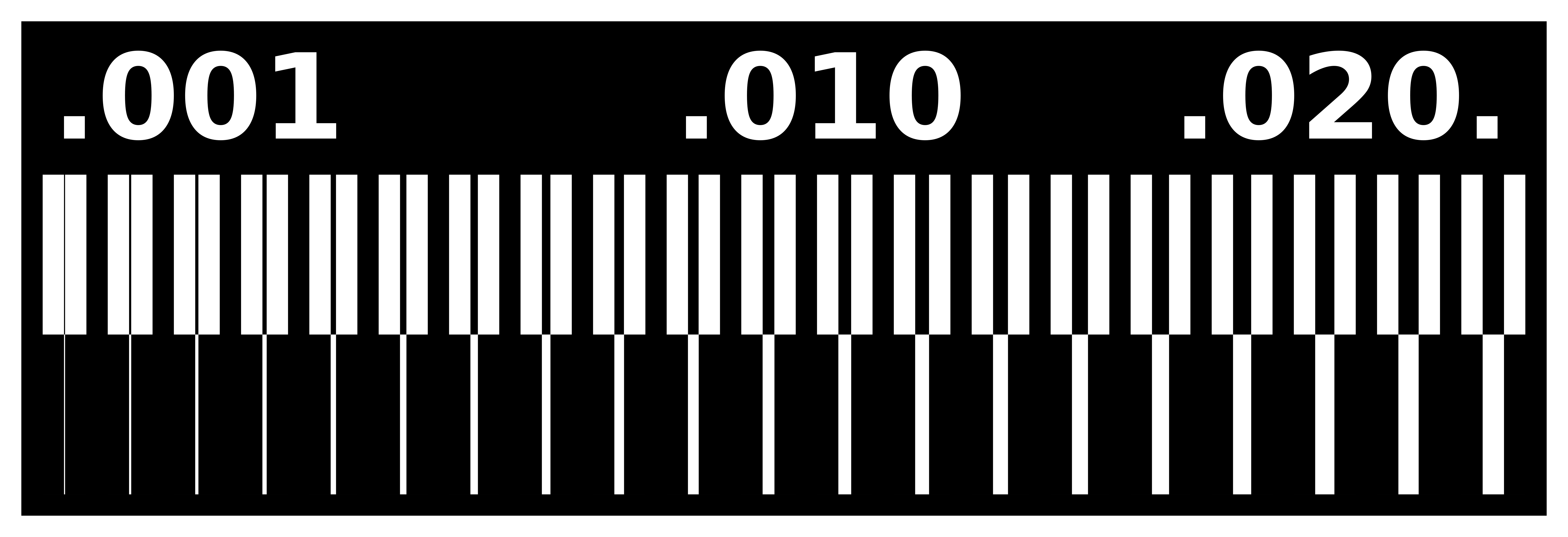
To start testing, we first generated a gcode test ruler file based on this trace image, and this outline image using Fab Modules. We imported these images into Fab Modules by selecting the image (.png) image format option and then selected the ruler traces file off of the computer. After that, we selected Othermill (.nc) as our output format, since our lab uses Othermill (Bantam) PCB milling machines, and this is the required file type for these machines. Nextly we selected the process operation and chose the 1/64” PCB bit, as this would be the bit we used while milling the traces on our ruler. Finally, we ran the Calculate process in Fab Modules and after this finished, we were able to download the .nc. Following this same process, we imported the ruler outline file into Fab Modules and processed the image into a Othermill (.nc) file with a 1/32” bit. After saving this file as well we moved these two .nc files over to a computer attached to one of our lab’s PCB mills. Here on this computer, we opened both of these .nc files in the Bantam Tools Desktop Milling Machine Software, the software that we use to prepare files and control out Bantam PCB mills. The process of using this software is written out in our milling workflow attached towards the top of this page. After importing our gcode files into the software, we positioned both in the bottom left corner of the workplace.
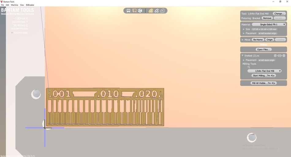
Once this file was prepared in the Bantam Tools Desktop Milling Machine Software, we prepared the mill by loading our stock material, a single-sided copper plate. This stock was stuck down to the bed of the mill with double-sided tape and aligned to the bottom left of the bed, the area where our test was positioned in the software. From here we installed a 1/64” bit into the tool so we could mill the trace on our test ruler, and located the bit position with the Tool Change feature in the Bantam software. After this, we probed our stock material by running the Bit Breaker feature witch probes the z height of the stock material by measuring distance until a circuit is completed by touching the bit to the PCB. After all this prep was completed, we were ready to run the traces cut of these test rulers.
Our first attempt at this traces cut returned with good results, and after its completion, we moved onto the cutting of the outline. Following the same steps as the traces cut, we imported out outline .nc file into the Bantam software, and then used the Tool Change feature to replace the 1/64” bit used for our traces with a 1/32” bit we would be using for the outline. Our material had already been probed for the first step, so after installing the new bit, we rehomed the machine and started the traces cut. Unfortunately, our positioning job when aligning this outline file in the bottom left file was a little off, as, on the second pass of the outline, the bit ran into the metal alignment bracket on the bed and snapped. We stoped our cut, replaced the bit, and then realigned the outline file moving it slightly up and to the right. We ran this cut again, not running into the bracket this time, and finished the outline pass of our test ruler.
Results
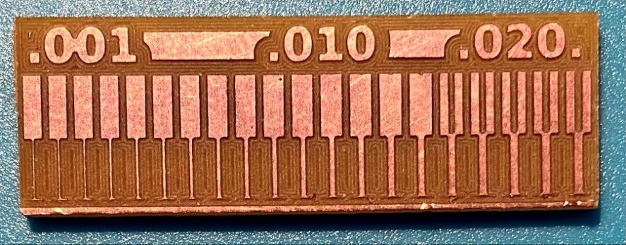 Our ruler test yielded good results, with the smallest trace of 0.001” being milled, as well as a trace clearance of 0.016” being cut.
Downloads
Click here to get access to our test files, the Machines workflow used, as well as the machines manual