Input Devices
Assignment - Input Devices
- I -- group assignment:
- probe an input device's analog levels and digital signals
- II -- individual assignment:
- measure something: add a sensor to a microcontroller board that you have designed and read it
- Individual assigment
-
To solve this week’s task I used an ultrasonic sensor that I connected to a PCB I made.
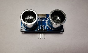
 The parts I needed are:
- PCB board
- ultrasonic sensor
- capacitor
- resistor
- connectors for components
- Design and making of PCB
-
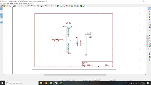
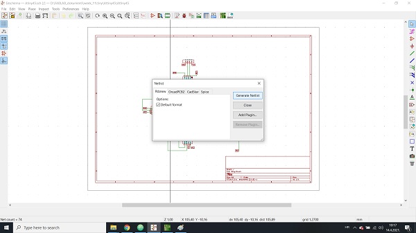
In order to make a PCB board, I first made a scheme with the help of the Kicad program, in which I connected all the necessary components. After I inserted and connected the necessary components it was necessary to generate a net list.
-
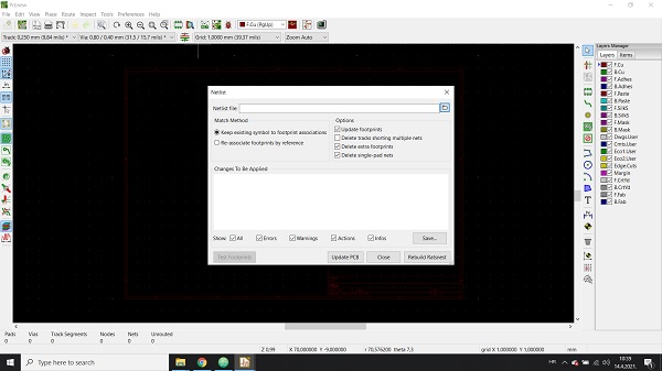
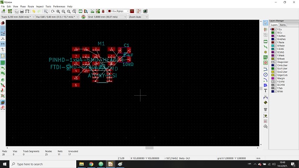
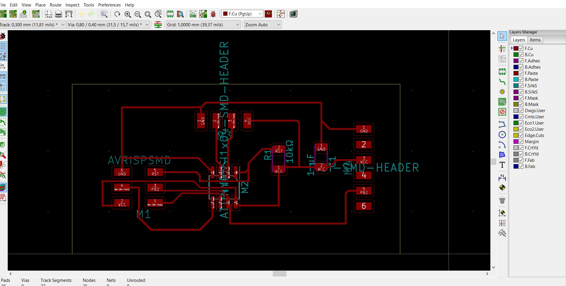
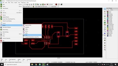
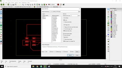
I inserted the generated net list into PCB new. After that, I arranged the components on the pcb. After adjusting the parameters for the tracks and the tile size, I exported the svg.
-
Arranged the components on the pcb
Export svg
-
SVG
3D view of PCB
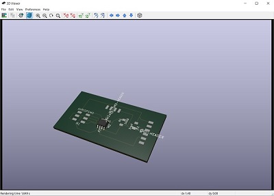
-

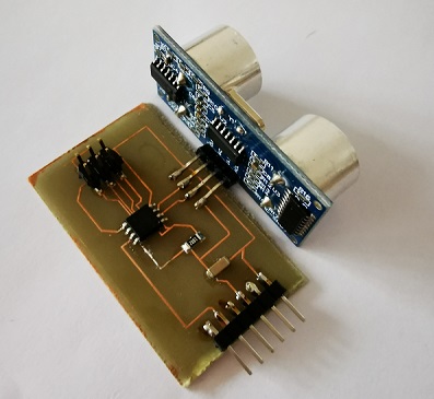
After I designed the PCB board it was necessary to make it. I made my tile using the photo procedure described in week 08. After that procedure, I got the PCB shown on the left. After that, I soldered the necessary components to the intended place for them.
I could now program the microcontroller to work with an ultrasonic sensor.
- Ultrasonic sensor
-
 Ultrasonic ranging module HC - SR04 provides 2cm - 400cm non-contact
measurement function, the ranging accuracy can reach to 3mm. The modules
includes ultrasonic transmitters, receiver and control circuit. The basic principle
of work:
- Using IO trigger for at least 10us high level signal,
- The Module automatically sends eight 40 kHz and detect whether there is a pulse signal back.
- IF the signal back, through high level , time of high output IO duration is the time from sending ultrasonic to returning.
Test distance = (high level time×velocity of sound (340M/S) / 2 -
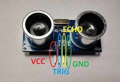 Wire connecting pins:
- VCC - 5V Supply
- TRIG - Trigger Pulse Input
- ECHO - Echo Pulse Output
- GND - 0V Ground
Electric Parameter
- Working Voltage DC 5 V
- Working Current 15mA
- Working Frequency 40Hz
- Max Range 4m
- Min Range 2cm
- MeasuringAngle 15 degree
- Trigger Input Signal 10uS TTL pulse
- Echo Output Signal Input TTL lever signal and the range in proportion
- Dimension 45*20*15mm
-
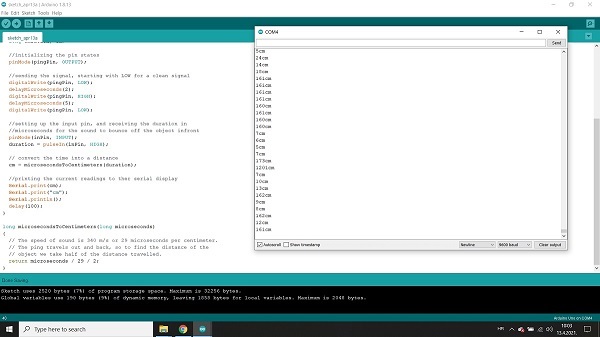
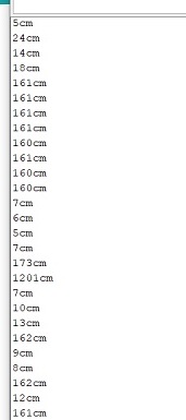
I connected the sensor board to the computer using an Arduino and programmed it. Moving the object in front of the sensor caused the distance of the object from the sensor to be read.
-
- Group assigment
-
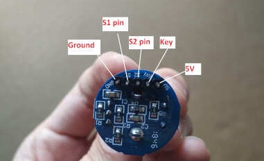
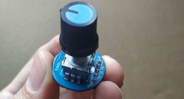
For the group assignment we had to probe an input device’s analog levels and digital signals. We used rotary encoder for digital signal and potentiometer for analog signal. A rotary encoder is a type of position sensor which is used for determining the angular position of a rotating shaft. It generates an electrical signal, either analog or digital, according to the rotational movement. This rotary encoder is also known as quadrature encoder or relative rotary encoder and its output is a series of square wave pulses. Iit’s the simplest position sensor to measure rotation. On the following picture you can see encoder pinouts.
-
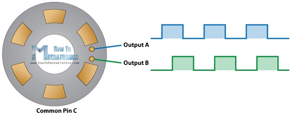
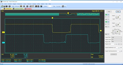
The encoder has a disk with evenly spaced contact zones that are connected to the common pin C and two other separate contact pins A and B (in our case is S1 and S2).When the disk will start rotating step by step, the pins S1 and S2 will start making contact with the common pin and the two square wave output signals will be generated accordingly. Any of the two outputs can be used for determining the rotated position if we just count the pulses of the signal. However, if we want to determine the rotation direction as well, we need to consider both signals at the same time. The following signal is obtained from oscilloscope when we was turning rotary encoder in clockwise direction. We set trigger mode on oscilloscope to single and trigger style to detect edge. We can notice that CH2 or S2 pin trigger faster than CH1 (S1 pin). Next signal is obtained from oscilloscope when we turn rotary encoder in counterclockwise direction. We can notice that CH1 or S1 pin trigger faster than CH2 (S2 pin). On this way we can determine the rotation of encoder, either clockwise or counterclockwise.
-
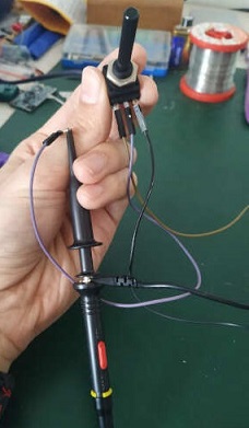 To observe the analog signal we used ordinary potentiometer.
Potentiometer has three terminals. The outer left and right in our case are fixed value and that was 25KΩ.
The middle pin is wiper (adjustable value).
we connect outer left and right terminal to 5 volts and ground.
The middle pin we connected to oscilloscope probe.
At its base, an analog signal is a continuous signal in which one time-varying quantity (such as voltage, pressure, etc.)
represents another time-based variable.
In the following video you can see how the analog signal changes when we turn potentiometer.
The values vary from 0V to 5V.
-