Computer-Aided Design
Assignment - Computer-Aided Design
- model (raster, vector, 2D, 3D, render, animate, simulate, ...) a possible final project, compress your images and videos, and post it on your class page
- ONSHAPE
-
Since I teach my students to work with AutoCad, Inventor and Catia I chose the not so familiar program for me - Onshape.
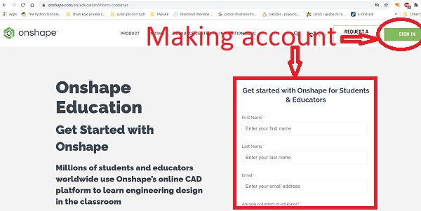 First I made account on Onshape web page.
After that, I studied a few videos to get acquainted with the basics of the program and its possibilities.
The basics of the Onshape program.
The system is cloud-based and comes with version tools, design, and collaboration features that allow these users to come
together whatever web browser or the device they’re using, resulting in products that are built
at a quicker pace and with less hassle.
Design teams don’t have to worry about software licenses or having to copy files as Onshape lets users
access the single master CAD data version securely and instantaneously.
Collaboration and sharing, assembly modeling, drawings, part modeling, and on-cloud access are just some of the
powerful features provided by Onshape. They do not expire and are available in the enterprise plan,
the professional plan, and even in the free plan.
First I made account on Onshape web page.
After that, I studied a few videos to get acquainted with the basics of the program and its possibilities.
The basics of the Onshape program.
The system is cloud-based and comes with version tools, design, and collaboration features that allow these users to come
together whatever web browser or the device they’re using, resulting in products that are built
at a quicker pace and with less hassle.
Design teams don’t have to worry about software licenses or having to copy files as Onshape lets users
access the single master CAD data version securely and instantaneously.
Collaboration and sharing, assembly modeling, drawings, part modeling, and on-cloud access are just some of the
powerful features provided by Onshape. They do not expire and are available in the enterprise plan,
the professional plan, and even in the free plan.
-
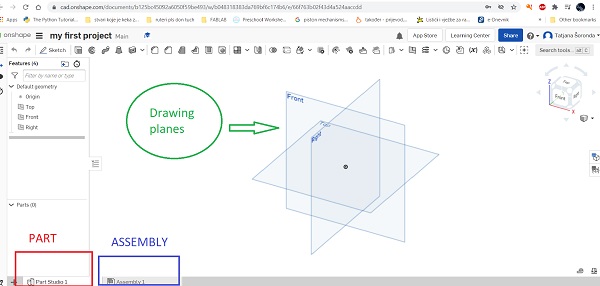 On the home screen in the center are the drawing planes - front, top, right.
At the bottom of the screen I can choose to draw a part or assembly.
For the first attempt, I chose to draw a part.
On the home screen in the center are the drawing planes - front, top, right.
At the bottom of the screen I can choose to draw a part or assembly.
For the first attempt, I chose to draw a part.
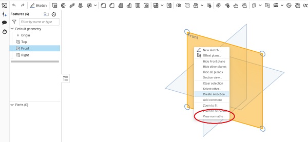
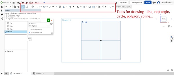 For a start, I selected FRONT on the left side of the screen then right-click on the plane- FRONT and select -
View normal to.Then I created a sketch in which I could draw my part.
For a start, I selected FRONT on the left side of the screen then right-click on the plane- FRONT and select -
View normal to.Then I created a sketch in which I could draw my part.
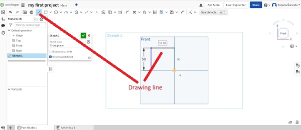
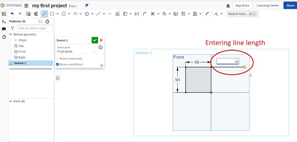 I drew a square using lines.
Of course, the square can also be created with the rectangle command by selecting
the beginning and end of the square, and then the dimension of width and height is entered.
I drew a square using lines.
Of course, the square can also be created with the rectangle command by selecting
the beginning and end of the square, and then the dimension of width and height is entered.
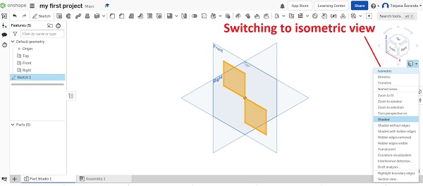
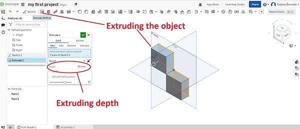 To see in drawing planes how my part looks like I switch my view to isometry.
After that, I extruded the object with the extrude command,
determining the extrusion thickness.
To see in drawing planes how my part looks like I switch my view to isometry.
After that, I extruded the object with the extrude command,
determining the extrusion thickness.

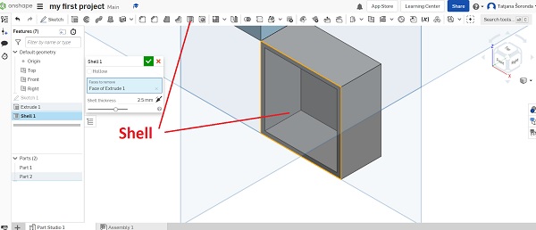 Drawing holes, shells, etc. is very simple.
The appropriate command is selected and parameters are selected - such as the type of hole, thread, depth, etc.
Drawing holes, shells, etc. is very simple.
The appropriate command is selected and parameters are selected - such as the type of hole, thread, depth, etc.
 What I liked about this program is that the interface is user friendly.
Complicated objects can also be drawn in a faster and simpler way.
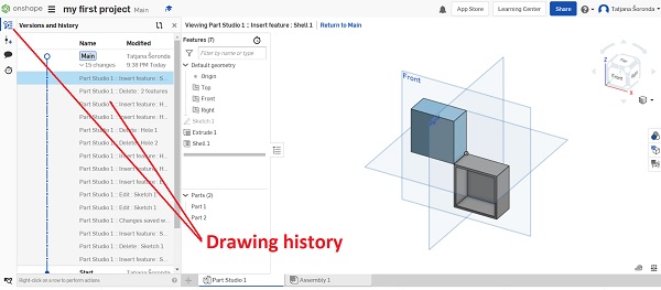
What I also liked is that it has a drawing history so it
can easily go back to the required step by clicking on it
and drawing a second independent drawing about the first one.
What I liked about this program is that the interface is user friendly.
Complicated objects can also be drawn in a faster and simpler way.
What I also liked is that it has a drawing history so it
can easily go back to the required step by clicking on it
and drawing a second independent drawing about the first one.
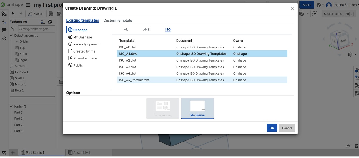
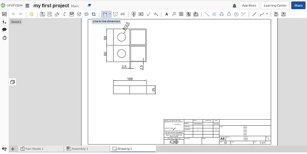 In addition, there are a number of templates that can be used to create drawings - ANSII, ISO
 After that, it is selected which parts will be placed on the drawing - individually,
the assembly and then they can be quoted, set tolerance marks, surface roughness,
cross sections, etc. You can add an image, another dxf drawing ...
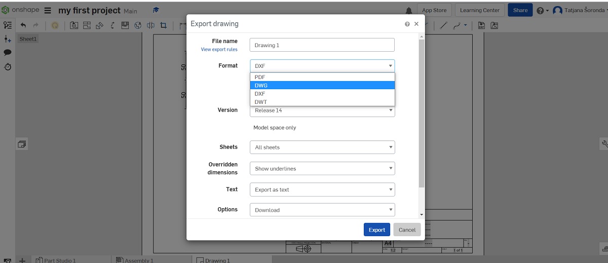
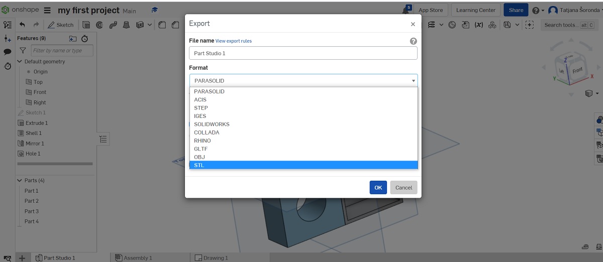
After completing the drawing and its parts, the drawing can be exported
as pdf, dwg, dxf, stl,...
After that, it is selected which parts will be placed on the drawing - individually,
the assembly and then they can be quoted, set tolerance marks, surface roughness,
cross sections, etc. You can add an image, another dxf drawing ...
After completing the drawing and its parts, the drawing can be exported
as pdf, dwg, dxf, stl,...
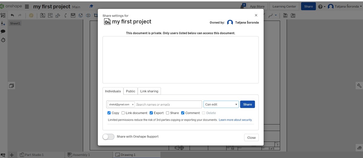 What I also liked about this program is the sharing of the same document
with other people, so everyone can work on the same drawing or project in real time,
which is interesting for working with students on assembly drawings.
What I also liked about this program is the sharing of the same document
with other people, so everyone can work on the same drawing or project in real time,
which is interesting for working with students on assembly drawings.
- SketchUp 2021
- GIMP
- Vector vs Raster Graphics: What’s the Difference?
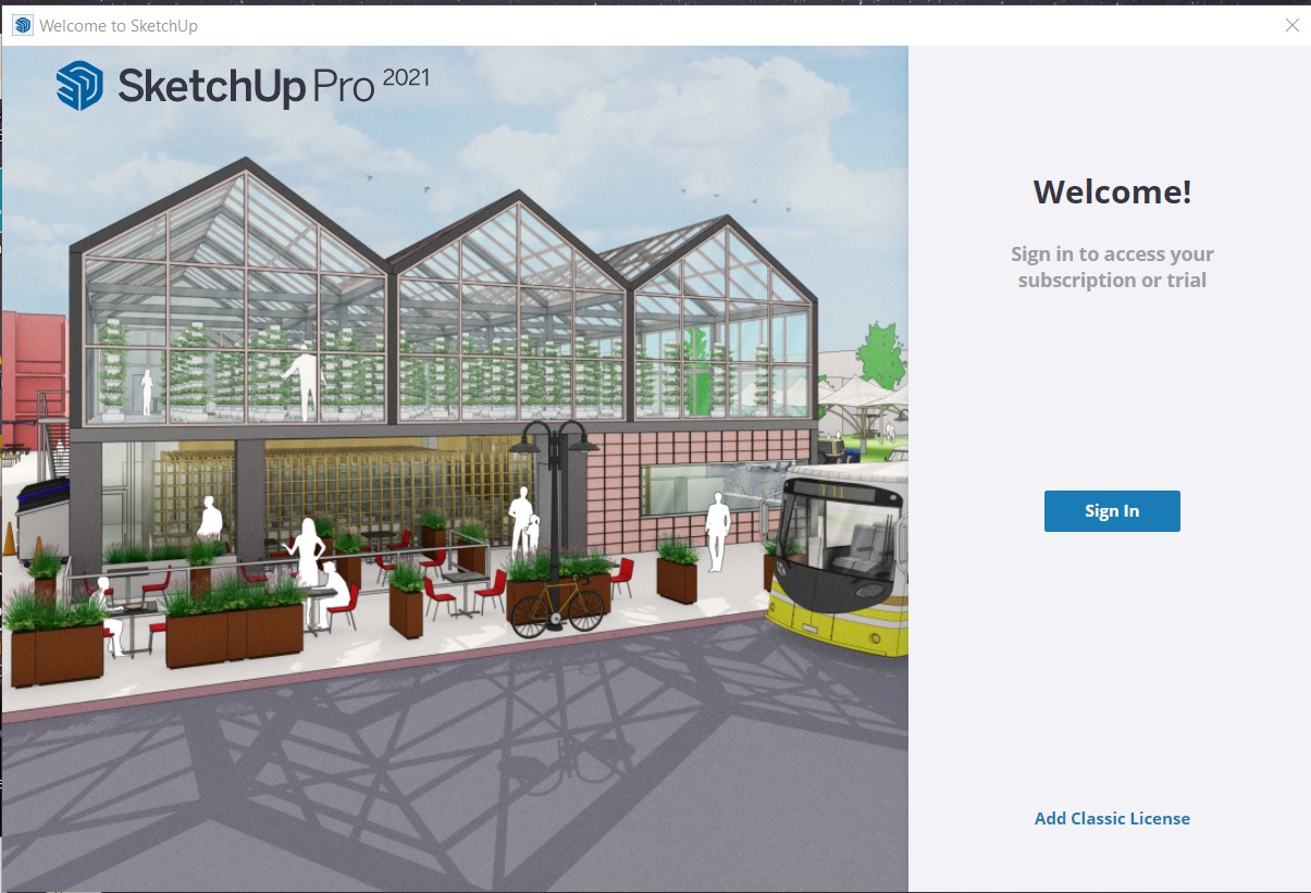 For the needs of the final project, I also used the SketchUp 2021 program.
I created an account and logged in.
For the needs of the final project, I also used the SketchUp 2021 program.
I created an account and logged in.
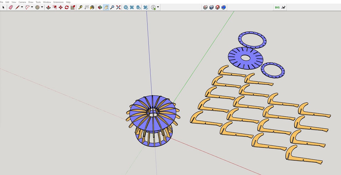
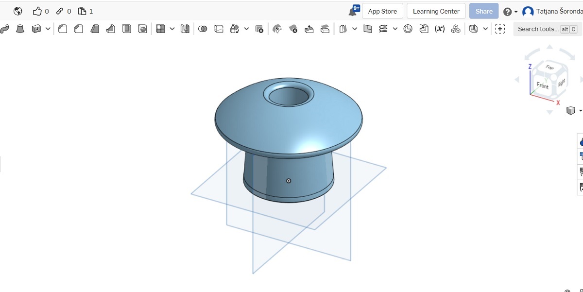 In OnShape, I drew the top of the lamp from which I will make the lamellae for the lamp.
 I loaded the stl file into SketchUp.

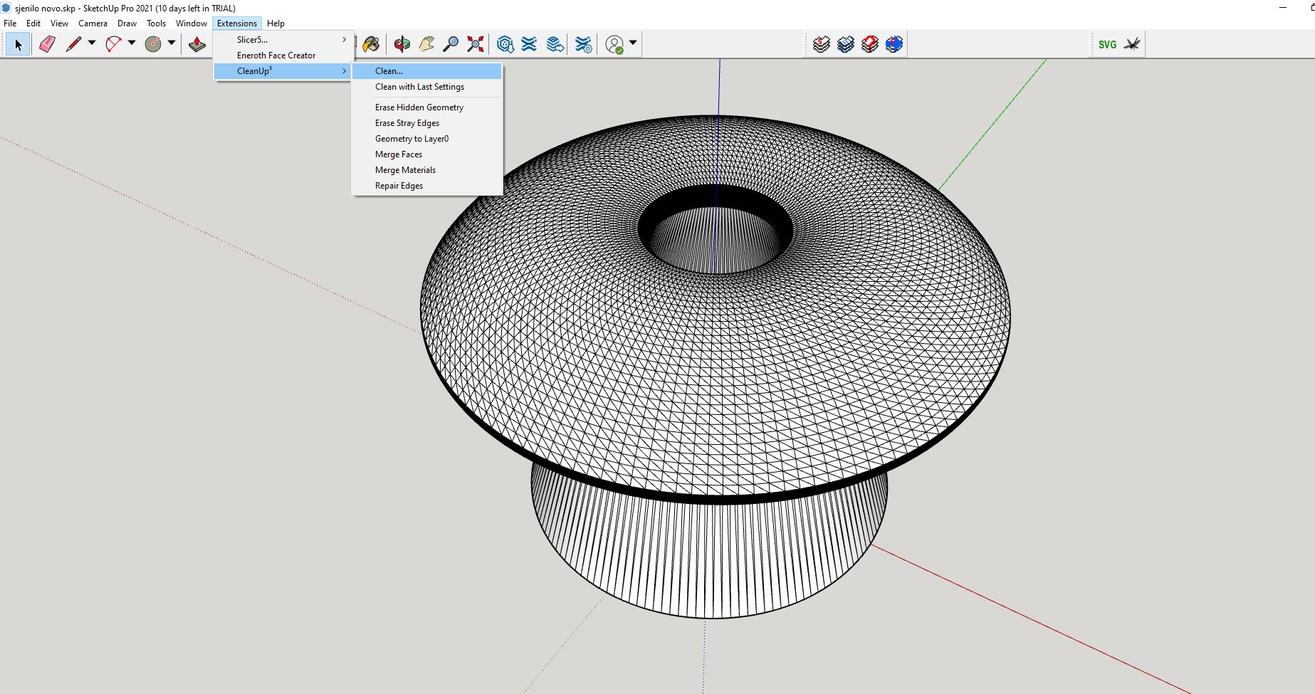
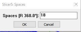 I chose which object I wanted to make a slice from and set the spacing of each slice.
 Final result ...
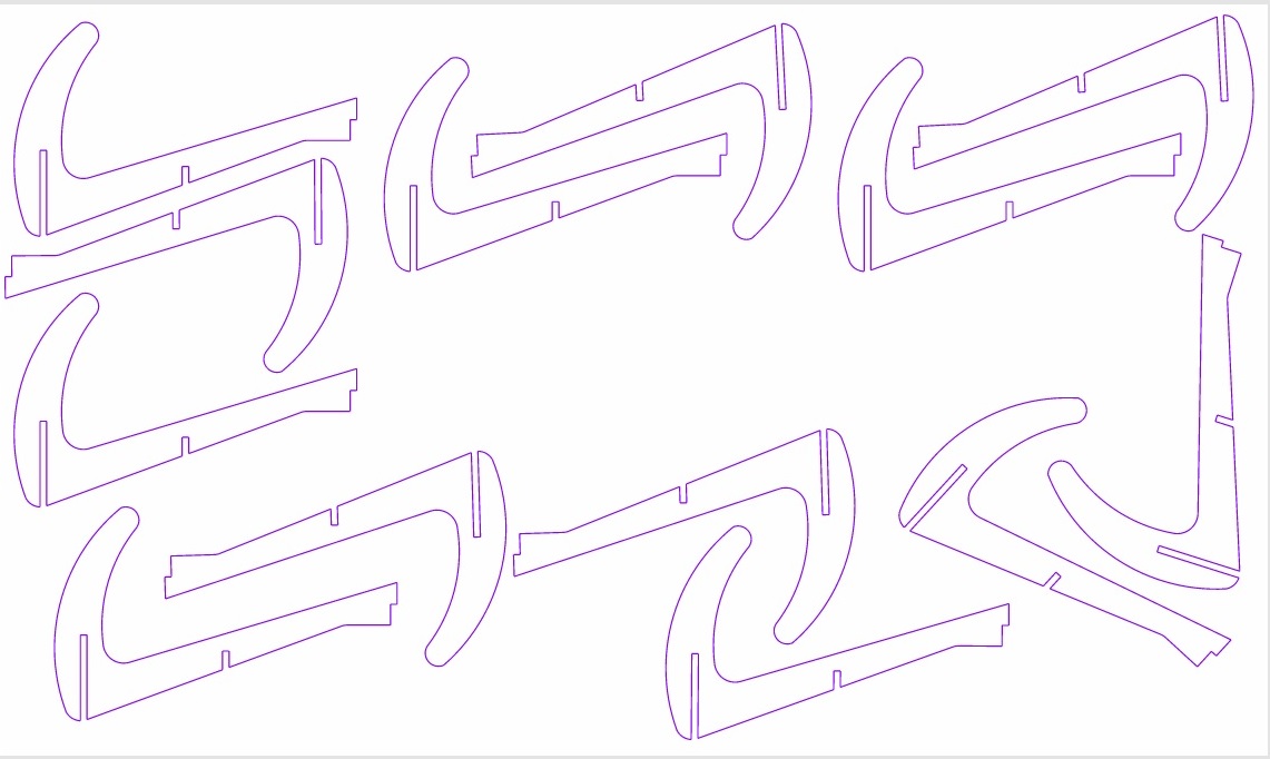 I got a DXF file that I could upload to Laserbox - a laser cutting program.
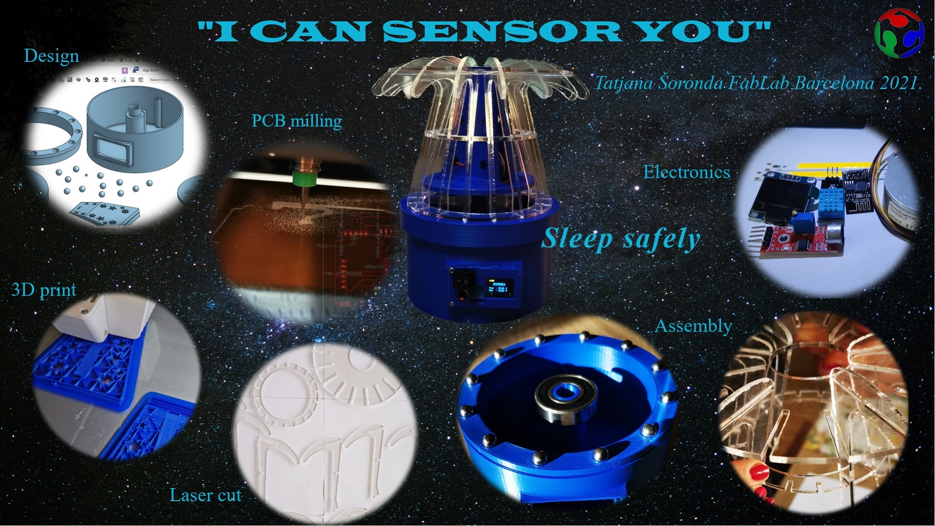 How I made the slide:
 First I opened up the GIMP and added all the pictures that i had taken into a new project.
Then I found which copyright free background picture I could use
First I opened up the GIMP and added all the pictures that i had taken into a new project.
Then I found which copyright free background picture I could use
 Then I create new image with dimensions (1920x1080).
Then I copy background picture on new image and change size of it to corespond image size
Then I create new image with dimensions (1920x1080).
Then I copy background picture on new image and change size of it to corespond image size
 I then used a elipse select tool (with feather 15 - for milde transition) on diferent picture and copy those selections to new image
 TI select part from picture.
 I move part to new position.
 Then I inserted a new layer on which I cut a part from the second image and moved it to the desired position.
 After adding all the pictures I wanted I inserted the text, I chose the type and size of the letter and its position.
 9. Last thing done is export picture as - presentation.png
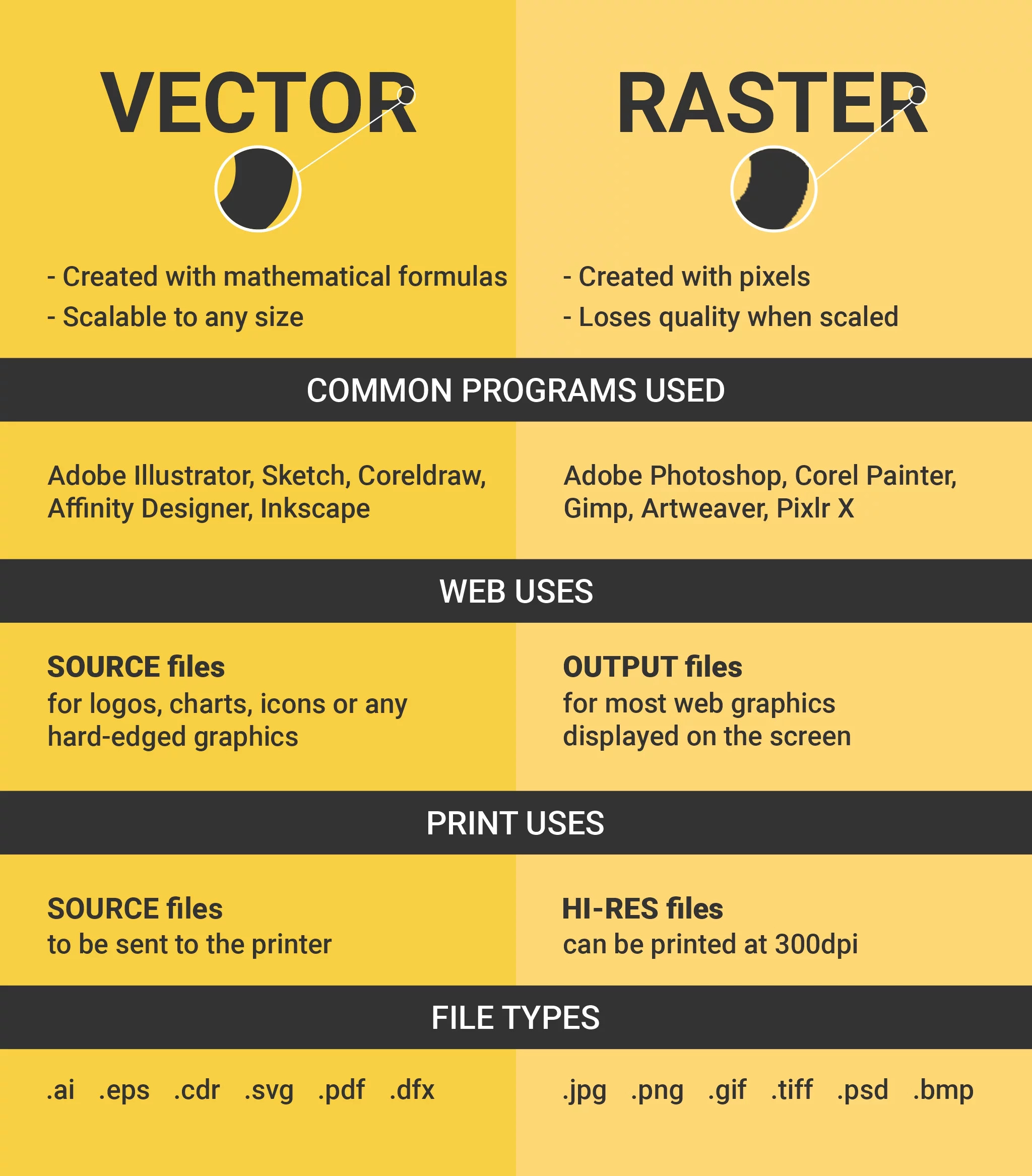
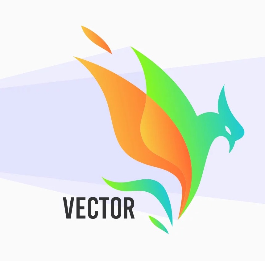 Vector files, made up of points and lines to create paths, can be scaled up and down without losing quality.
Constructed using mathematical formulas rather than individual colored blocks, vector file types such as AI,
EPS, CDR, SVG and PDF are makes vector files the best format for graphic assets such as illustrations,
icons and company logos, as the same file can be used for designs ranging from a mobile app to a large
billboard without sacrificing quality or increasing file size.
Vector files, made up of points and lines to create paths, can be scaled up and down without losing quality.
Constructed using mathematical formulas rather than individual colored blocks, vector file types such as AI,
EPS, CDR, SVG and PDF are makes vector files the best format for graphic assets such as illustrations,
icons and company logos, as the same file can be used for designs ranging from a mobile app to a large
billboard without sacrificing quality or increasing file size.
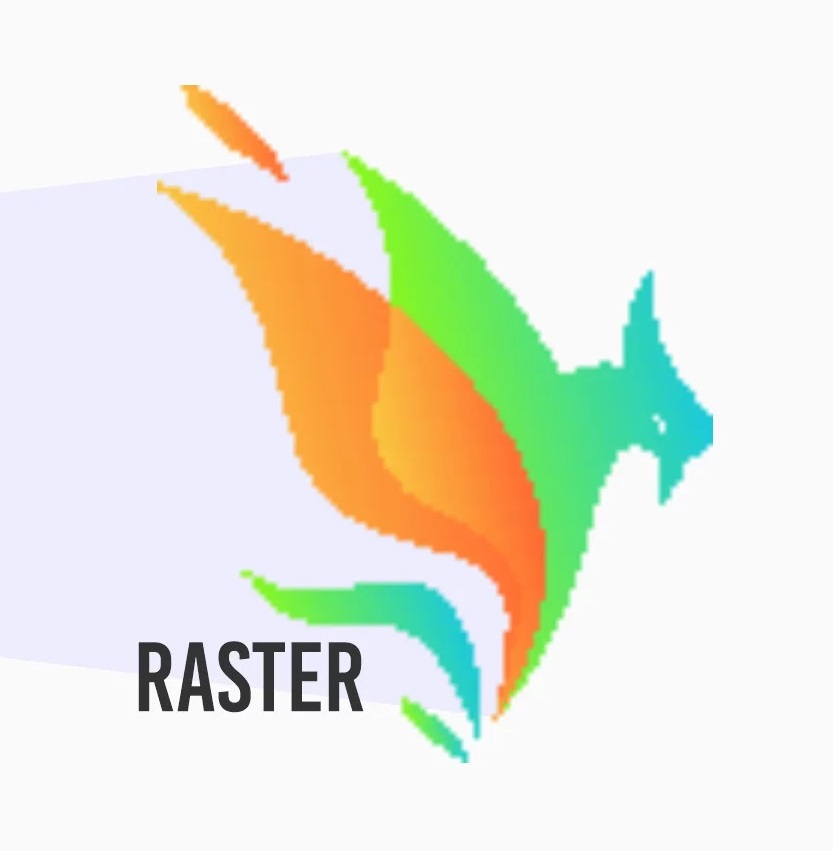 Raster images are made up of many tiny squares called pixels and are often referred to as ‘bitmap’ images.
When zoomed in closely, the individual pixels can be observed. The resolution of a raster file is referred
to as DPI (dots per inch) or PPI (points per inch),
and is the main determining factor for increasing file size. JPG, PNG, GIF and TIFFs are common raster image types.
Raster images are made up of many tiny squares called pixels and are often referred to as ‘bitmap’ images.
When zoomed in closely, the individual pixels can be observed. The resolution of a raster file is referred
to as DPI (dots per inch) or PPI (points per inch),
and is the main determining factor for increasing file size. JPG, PNG, GIF and TIFFs are common raster image types.