Electronics Production
Assignment - Electronics Production
- I -- group assignment:
- characterize the design rules for your PCB production process
- II -- individual assignment:
- make an in-circuit programmer that includes a microcontroller by milling and stuffing the PCB, test it, then optionally try other PCB processes
- Group assignment
-
To solve this week’s task I used Roland mill 15.
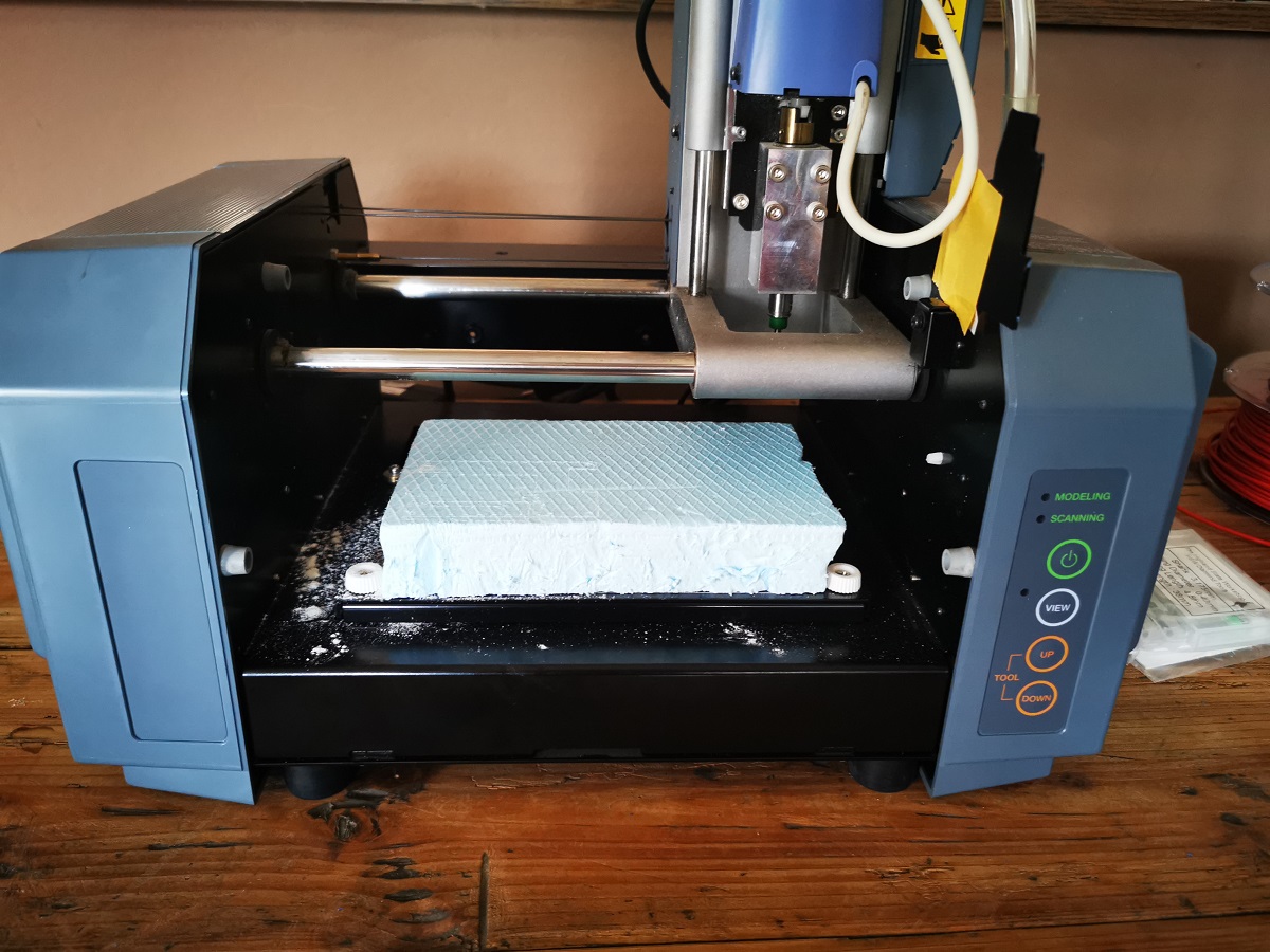
Roland mill 15:
-
Work space
- Longitudinal displacement (X-axis) mm 190
- Transverse displacement (Y-axis) mm 125
- Vertical offset (Z-axis) mm 190
- Effective height displacement (Z-axis) mm 120
- Distance of spindle forehead in height (vertical milling) mm 30-220
- Spindle head distance (horizontal milling) mm 82-272 Milling machine work table
- Work surface (Lx D) mm 420x125
- Maximum workbench load kg 10
- Width 2 T-slots mm 11
- T-slot spacing mm 90
- Individual assignment:
 For the group task I used the so-called linetest
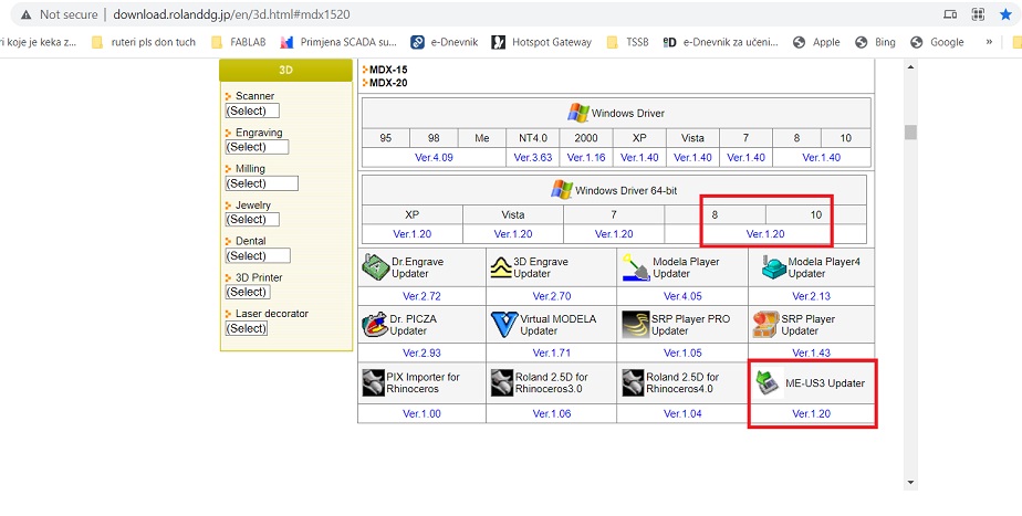 At first there were problems with the installation of programs and drivers for the Roland MDX-15,
however after a series of failures with the help of a colleague and instructor FabLab Barcelona we
were able to install everything needed to work.
At Roland MDX-15 we found the necessary
software and drivers for Roland MDX-15.
The ME-US3 driver must be installed first (this is a DB25 to USB cable).
Then I need to install the Windows driver.
For latter milling I will use Model player 4 and Virtual Model.
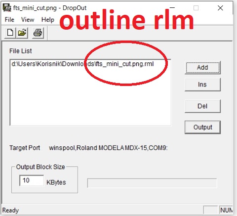
To send the code I used DropOut, it is here under utilities:
At DropOut
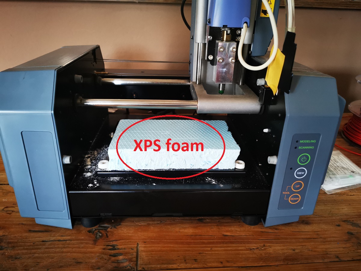
 After installing the program, it was necessary to prepare the surface of
the milling machine so that I glued XPS foam. The glue is double-sided adhesive tape.
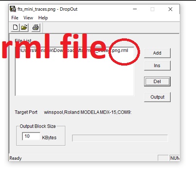 In order to convert the schematic display to a milling machine, it is necessary to convert the png file into an rml file.

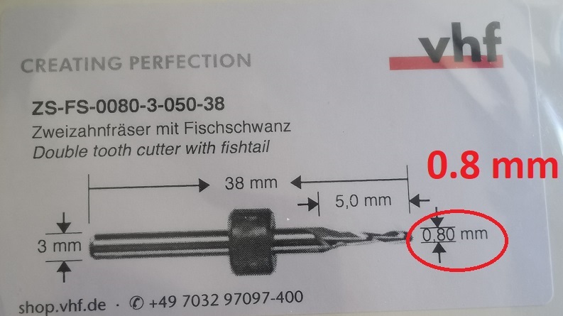 To create the traces, I used a mill diameter of 0.4 mm - picture on the left, and to create an outline line,
I chose a cutter 0.8 mm - picture on the right.
 To make the code for the milling machine I used modsproject.
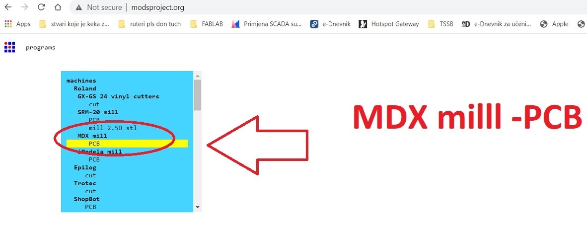 I select MDX mill -> PCB program.
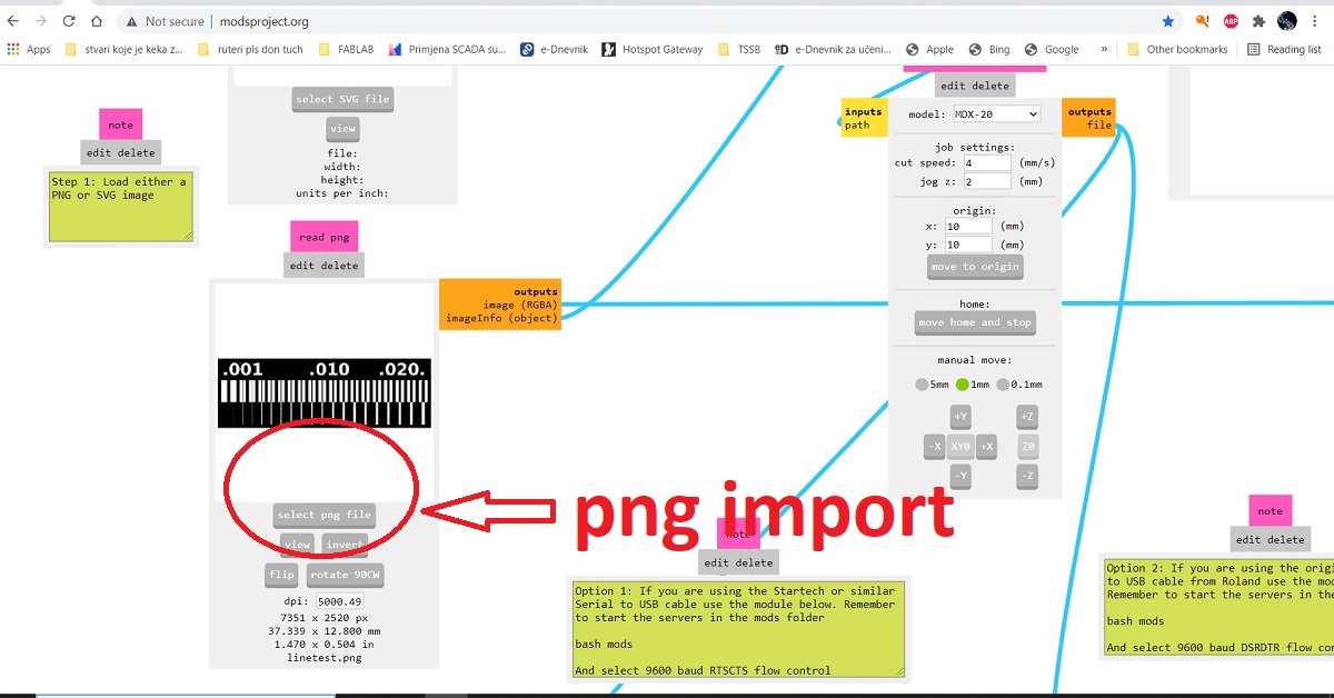 I chose the png i want to load.
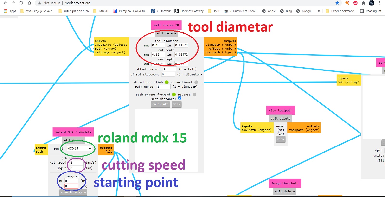 Then I chose the Roland MDX-15 milling machine. I determined the cutting speed - 1 mm / s,
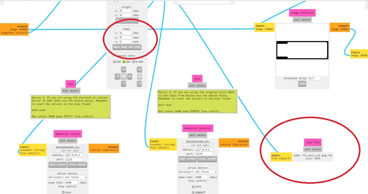
the starting position along the x axis and the y axis - 0.0, and along the z axis 5 mm.
Then I determined the diameter of the tool - 0.4 mm, and the depth of milling 0.12 mm.
I set the offset to 4.
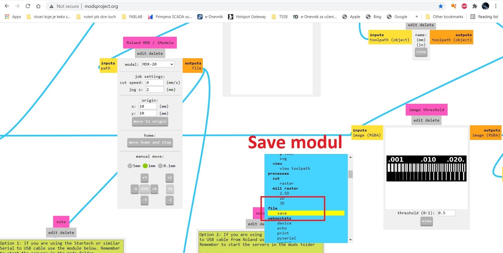 Then I inserted the file capture module.
This module will allow me to save a file to be loaded into the milling machine, which represents the tool paths.
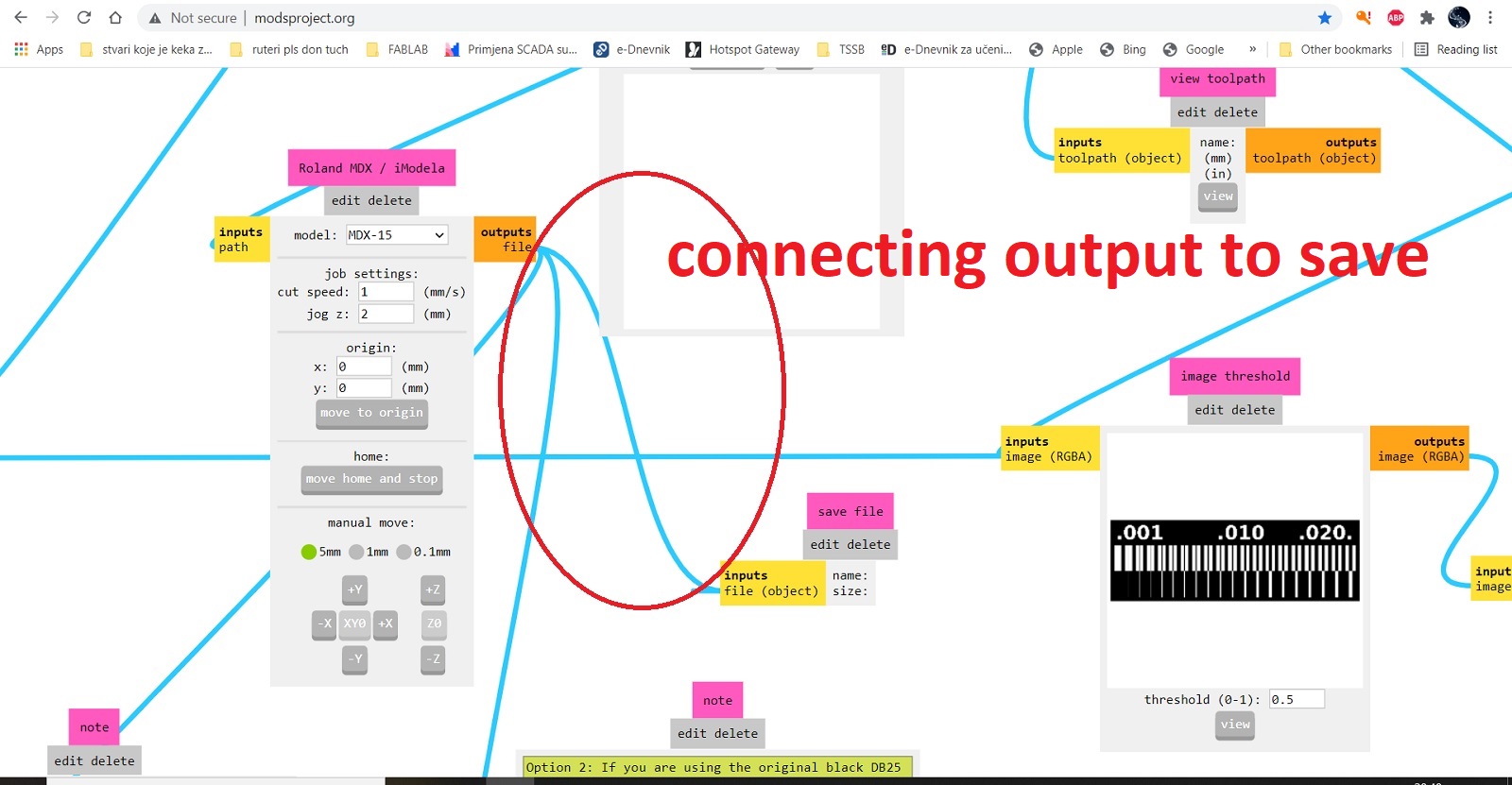 After setting up the module, I connected the input and output.
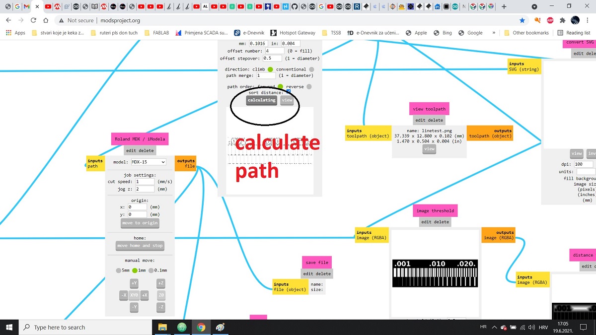 After that I clicked on calculate.
The file was ready for production on a milling machine.
I repeated the same procedure for Outline.png.
For traces I selected mill traces (1/64 ’’) and for outline (1/32’‘) .
Max depth for outline was 1.85mm to be sure to cut layer beneath pcb and cut depth of one pass is 0.6mm.
 The result is ....
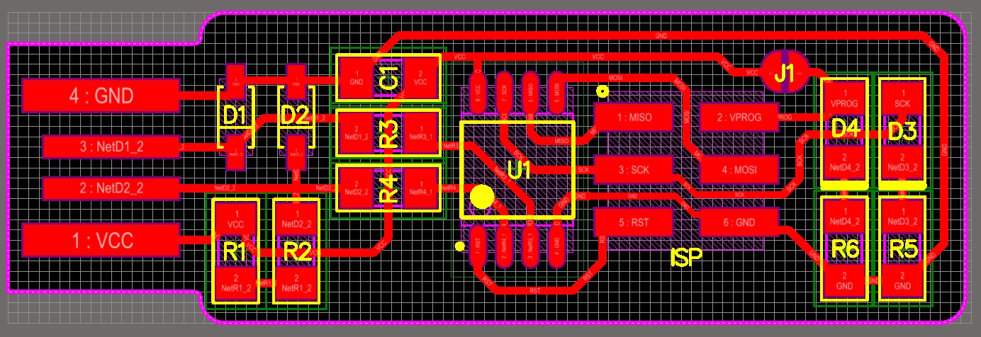 Now it was time for an individual task. I chose Brian’s FabTinyISP.

 From the website I download png files for traces and outline.
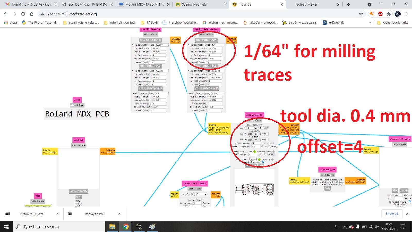 I repeated the same procedure at http://modsproject.org/ selecting the png images
I wanted to load, then setting the machine parameters and finally connecting the output to the save module.
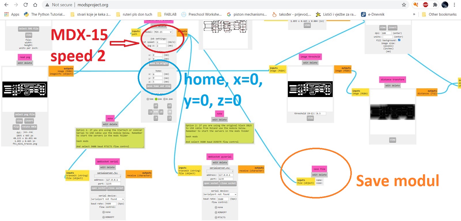
 After calculating the trajectory for the traces it looked like this
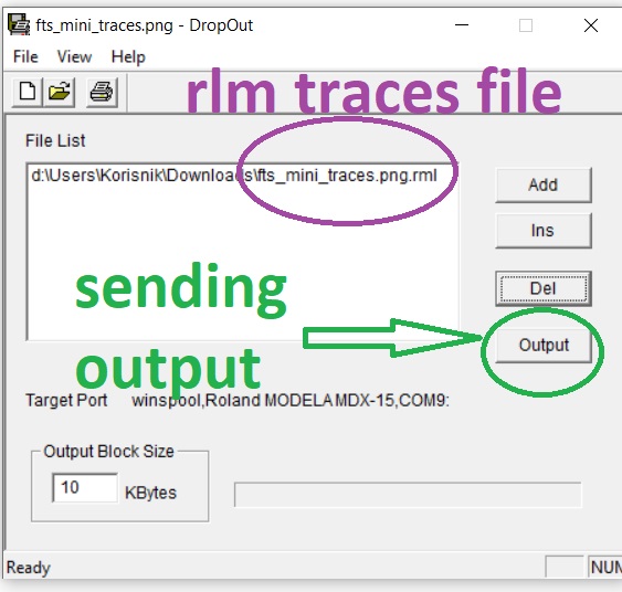 I loaded the resulting rlm file into the DropOut program.
After loading the png I set the z axis on the milling machine
and clicked the output in the program after which the milling machine started working.

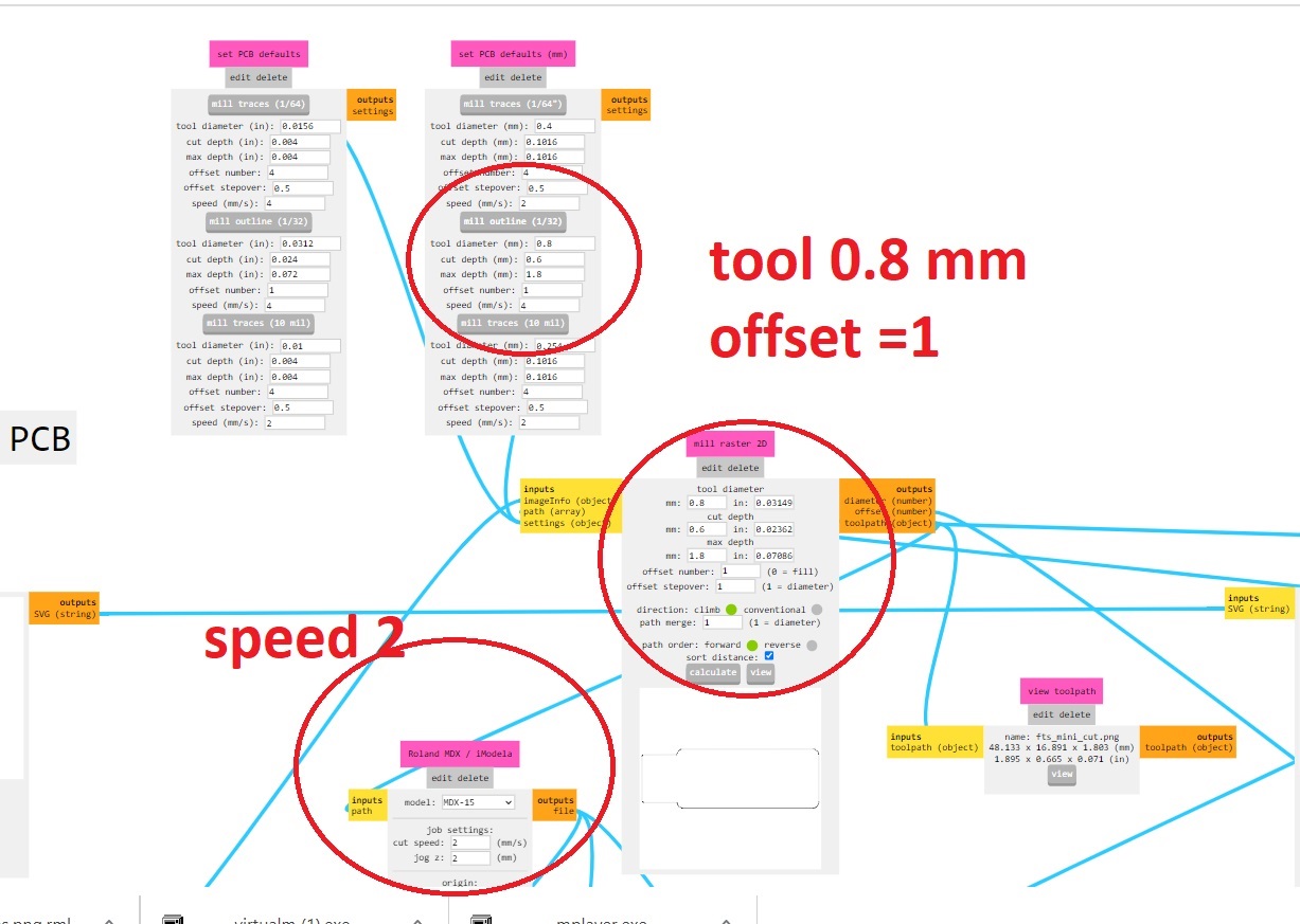 Setting parameters for outline
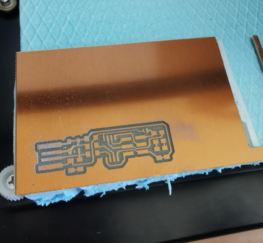
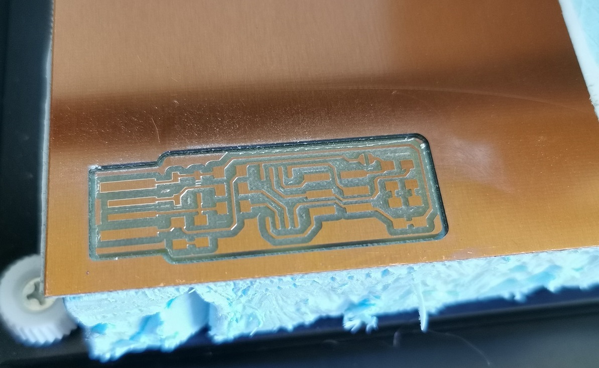 And the result is....
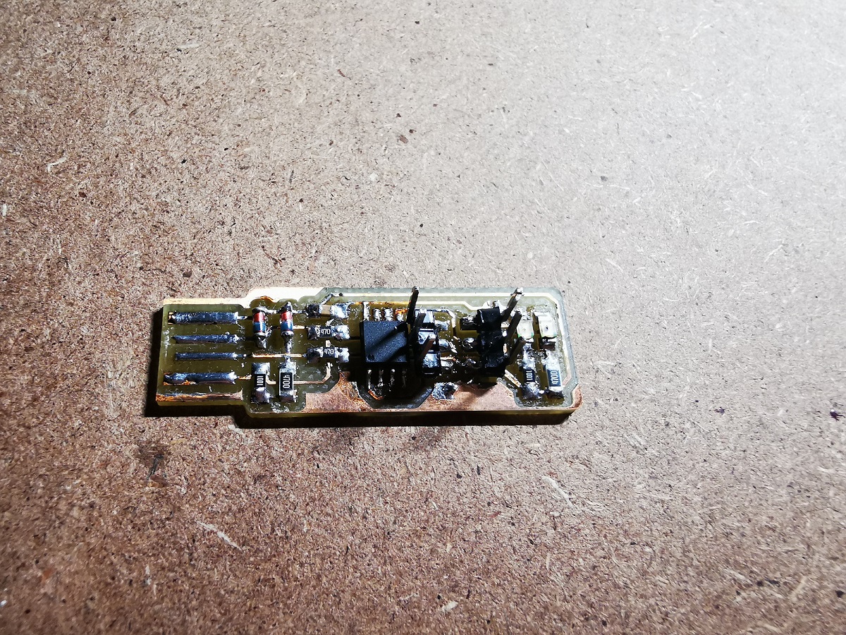 Now it was necessary to solder the components to the board and program it.
I took the following components and soldered them:
- 1x ATtiny85
- 2x 1kΩ resistors
- 2x 470Ω resistors
- 2x 47Ω resistors
- 2x 3.3v zener diodes
- 1x red LED
- 1x green LED
- 1x 100nF capacitor
- 1x 2x3 pin header
For my first attempt at more serious soldering it went well.
I had to thicken the USB wires a bit because there was no contact and I cleaned up the excess copper left between them when milling.
 In order to know where to solder, I followed the schemes

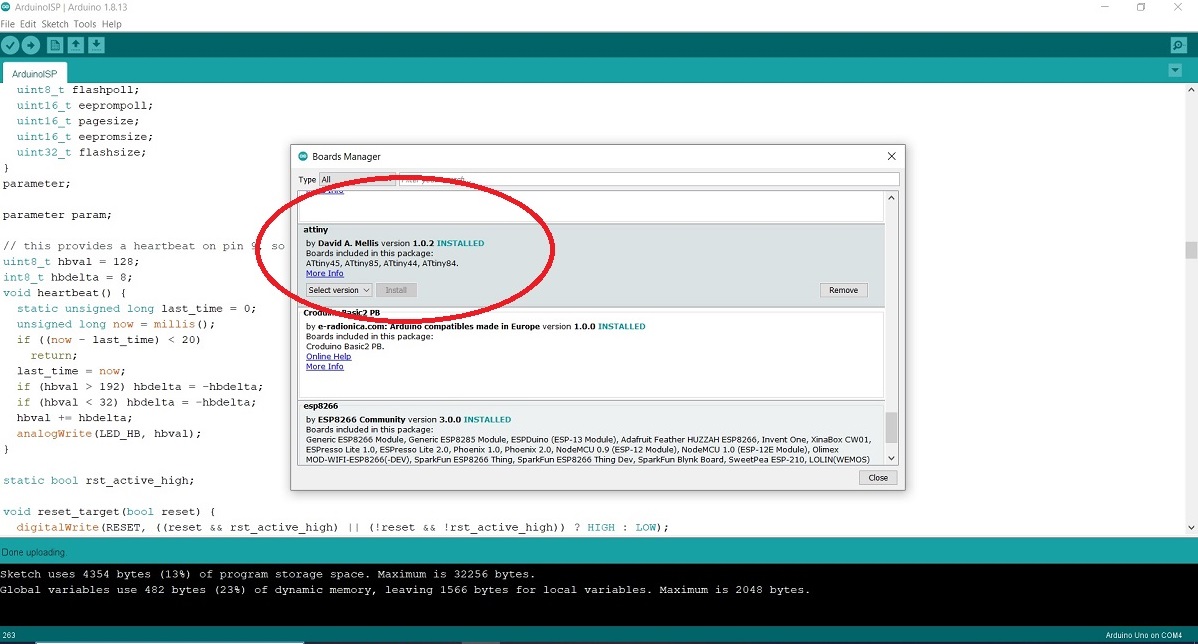 Since I don't have an AVRISP programmer I used an Arduino Uno.
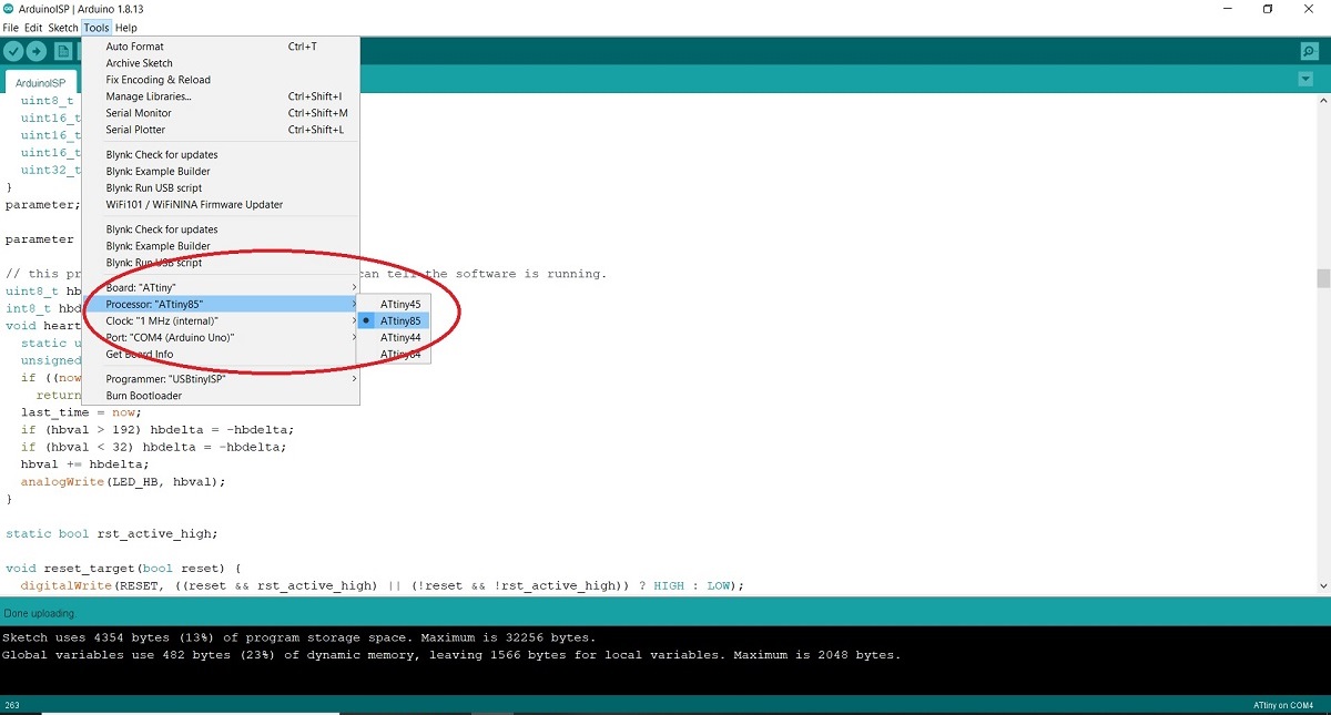
I added ATtiny to Arduino.
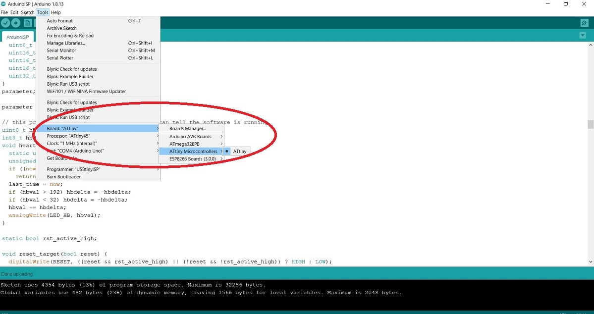 Since I don't have an AVRISP programmer I used an Arduino Uno.
I added ATtiny to Arduino using the built-in boards manager.
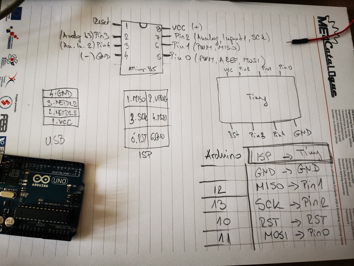 Now I need to provide power to the ATtiny and connect it to programmer. I connect MISO, MOSI, SCK, RESET, VCC, and GND of
the programmer to the corresponding pins on the ATtiny.
For that I used my sketches to know which port goes where, ie which input/output on ATtiny85 are the corresponding inputs and outputs on the Arduino.
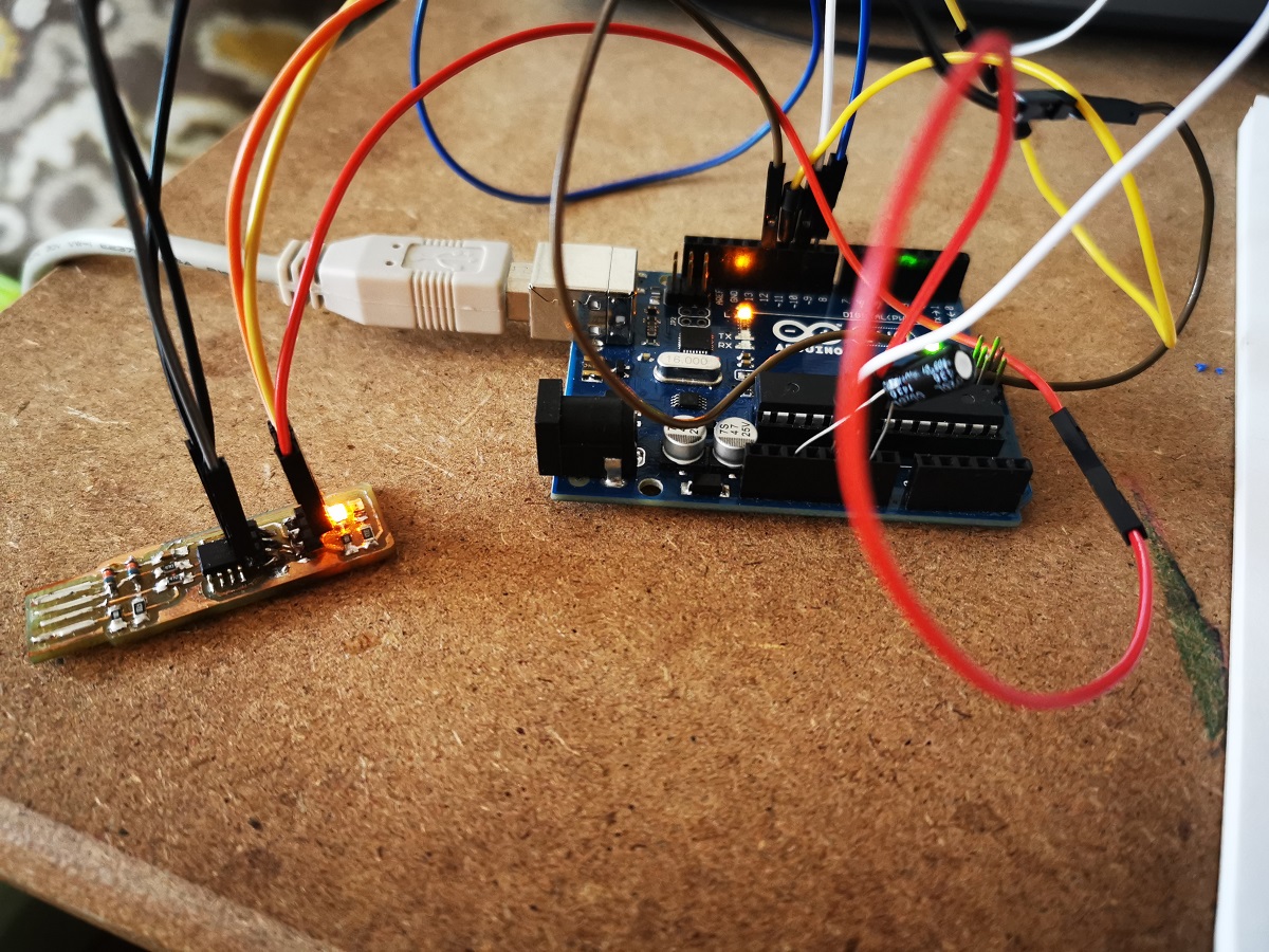 I connect the Arduino board to the ATtiny as shown in my sketch.
I also connect a 10 uF capacitor between reset and ground on the Arduino board as shown in the diagram
(the stripe on the capacitor that’s marked with a negative sign (-) should go to ground).
The capacitor prevents the Arduino board from resetting (which starts the bootloader),
thus ensuring that the Arduino IDE talks to the ArduinoISP (not the bootloader) during the upload of sketches.
The capacitor is needed for Arduino Uno.
Pin connections:
- ATtiny Pin 2 to Arduino Pin 13 (or SCK of another programmer)
- ATtiny Pin 1 to Arduino Pin 12 (or MISO of another programmer)
- ATtiny Pin 0 to Arduino Pin 11 (or MOSI of another programmer)
- ATtiny Reset Pin to Arduino Pin 10 (or RESET of another programmer)
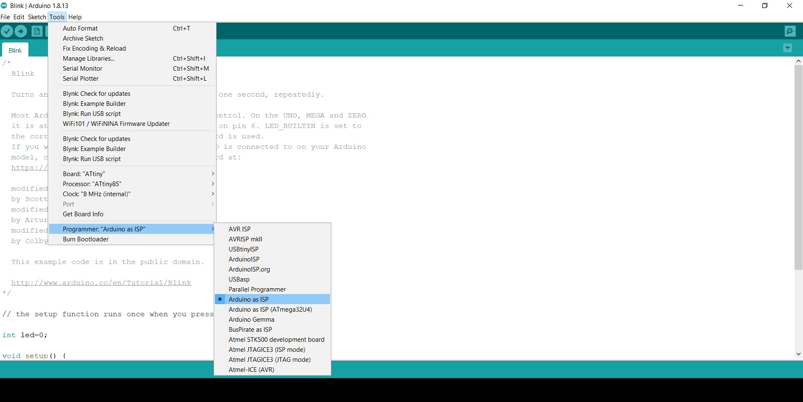 Next I use the ISP to upload a program to the ATtiny:
Open the Blink sketch from the examples menu.
Change the pin numbers from 13 to 0.
Select “ATtiny” from the Tools > Board menu and the particular ATtiny you’re using from the Tools > Processor menu.
Select the appropriate item from the Tools > Programmer menu
-“Arduino as ISP”
Upload the sketch.
