12. Output devices
For this group assignment, we evaluate the power consumption of output devices. We will focus on the stepper motor used in Quentin’s week assignment.
Stepper motor
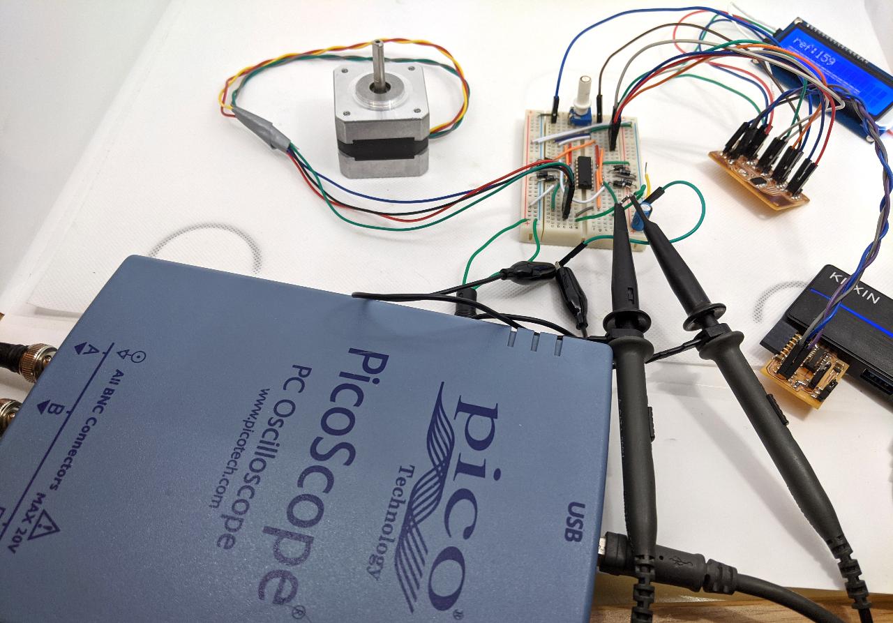
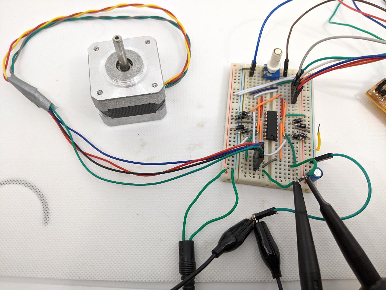
The stepper motor is driven by an H-bridge which inverts the polarity of the voltage. While the voltage value should remain approximately 5V, the current direction gets reversed. For that reason, we decide to make a differential measurement with an oscilloscope. We want to measure the voltage drop across a 4.7~\Omega resistor that we added in series with the motor’s winding. This will disturb the current’s value a bit, as the winding’s total resistor is now about 10\% higher. We can compensate for this when computing the power, but we will neglect this effect for now.
A closer look shows that the oscilloscope’s two channels have the same ground reference, but measure each side of the resistor.
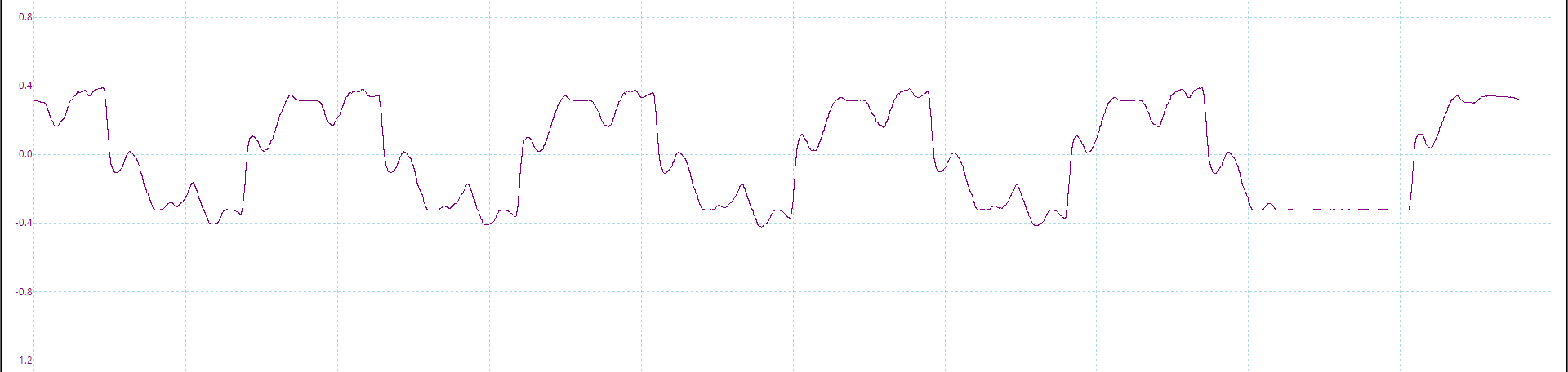
On the Picoscope software, we can see channels A and B, and the slight difference between them. When the motor turns, the voltage applied looks like a square waves with overshoots.

We add a differential channel between A and B.
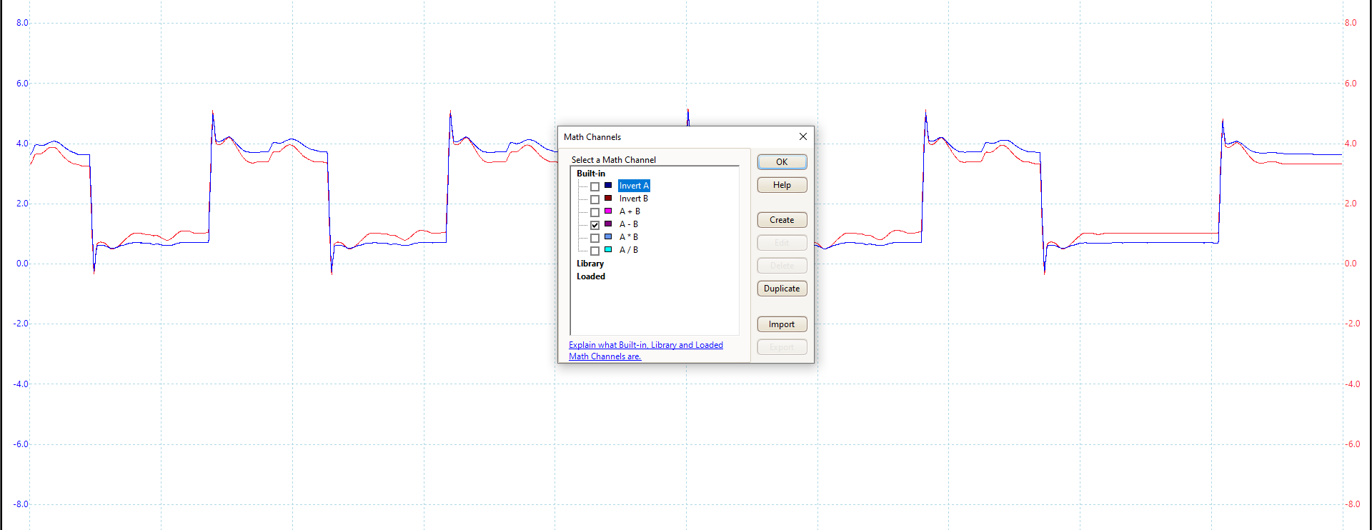
The new differential channel has a mean of 0, which is expected because the direction of the current is reversed every half-cycle.
The best way to estimate the overall power consumption is the RMS (displayed at the bottom).
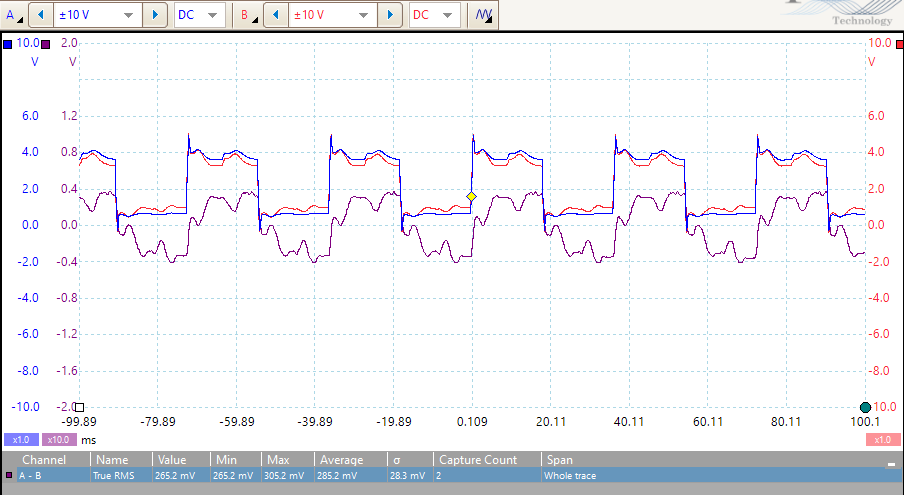
Knowing the probe resistor’s value, we can compute the RMS current as:
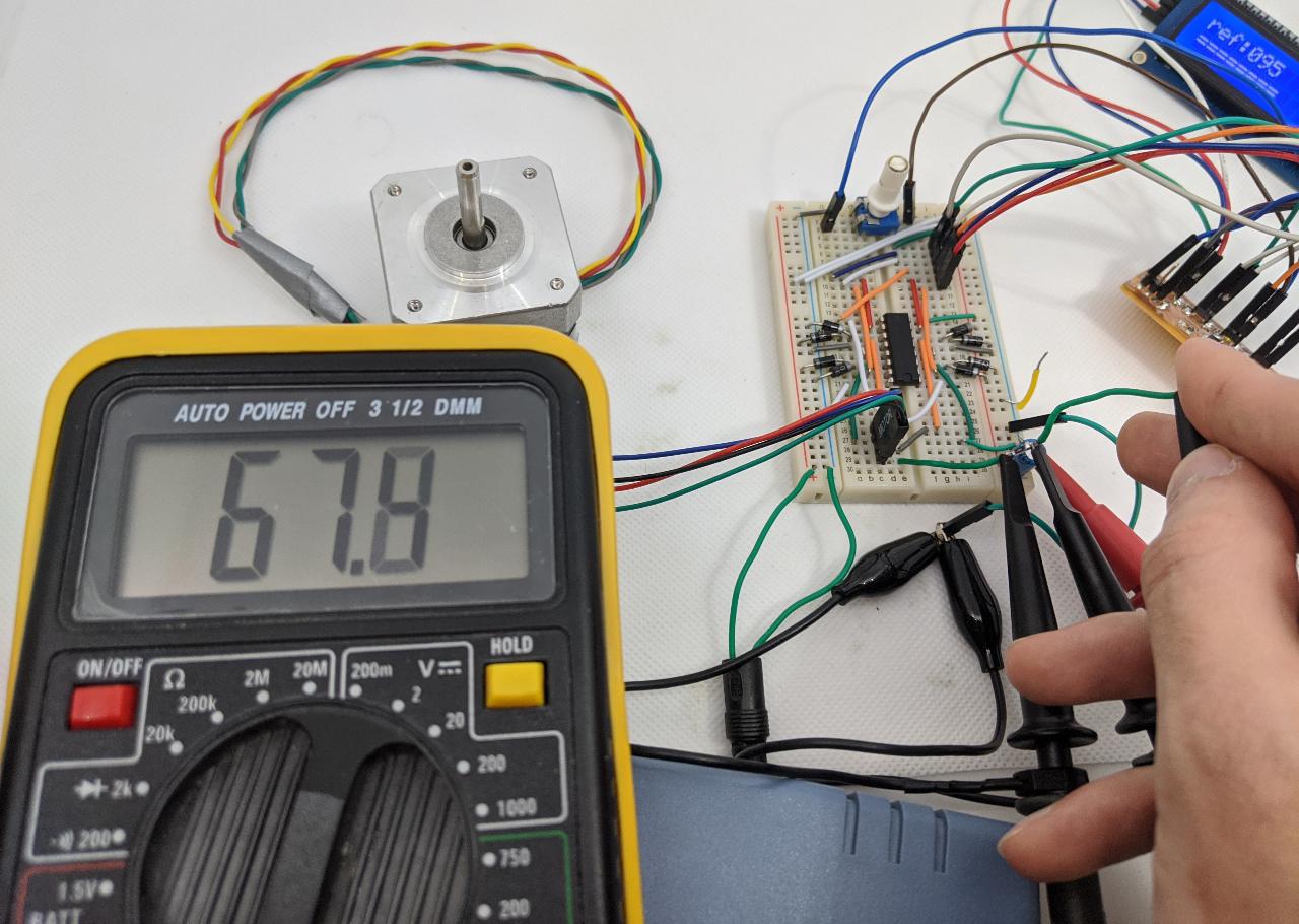
Assuming a RMS voltage V\approx 4V, we get to a power of P=VI\approx 0.24~{\rm W}. We can also check the power consumption when the motor does not turn:
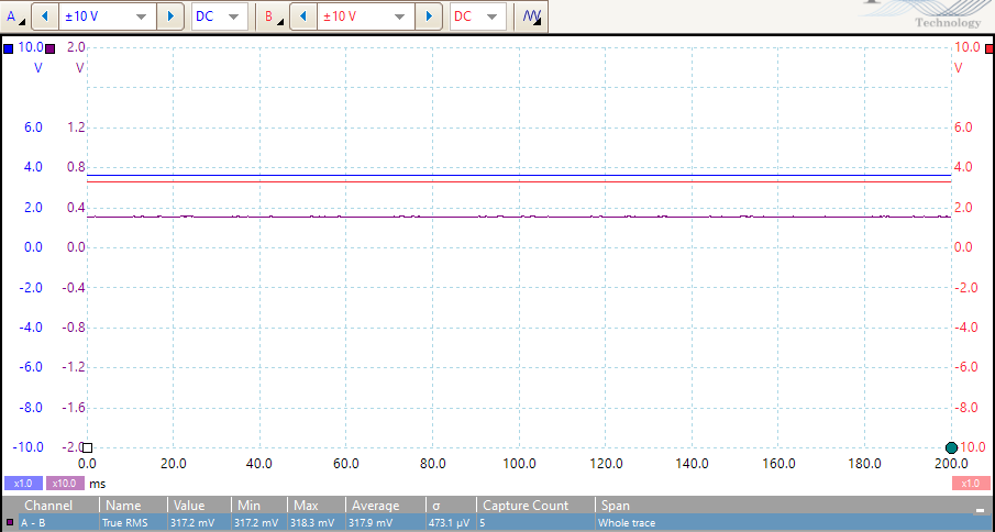
Which leads to I\approx 67.7~{\rm mA} and P \approx 0.27~{\rm W}. We can replace the oscilloscope with a current meter to confirm the value of the current. The value is not 100% stable but is close to what we estimated.