4. Computer controlled cutting
This week, our group assignment was centered around understanding and using the laser cutter. In summary, we had to:
- check the focus - What happens when you cut out of focus and in focus? Both recognize when focus is wrong to understand when it is worth to defocus.
- check the power - Start with cardboard and do a series where you go from too little to too much power.
- check the speed - Vary the cut speed and make a chart that go from low to fast.
- check the rate - Play with the rate (slow down and speed up the rate) and make a chart for different materials.
- measure the kerf - Compute the difference of measurements between a designed part and the cut part.
Our Lab is equipped with a Lasersaur laser cutter, which we will use for all assignments.
Focusing
The focus of a laser beam is the location along the propagation direction where the beam radius has a minimum. On the Lasersaur the focus tuning is manual. We knew from our predecessors that the focus of the Lasersaur on the superior layer of the material is at 15mm far from the upper layer. Therefore we decided to test the cutting capabilities of the machine for a set of different focus. Different 3D printed slip gauges helped us to precisely locate the laser beam at 11mm, 12mm, 13mm, 14mm, 15mm and 19mm from the surface of the material. Each time the focus was manually done we ran the program to cut a square of 2x2cm. We selected a power of 70% and a speed of 1200mm/min.
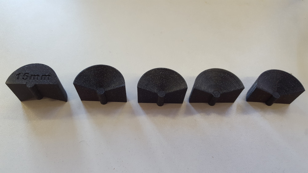
We observed that for the values from 11 to 15 mm the squares were properly cut with no significant difference between each other. We concluded that the laser beam was thin enough too not have a significant influence on the final cutting result.
With the laser being 19mm far from the upper surface of the material, we observe that square was not cut: It was profoundly engraved but it was not possible to detach it. We concluded that this characteristic might be very useful to enhance engraving capabilities but although very difficult to implement on a manually tuned focus machine.
Speed and power
To test both the speed and laser power simultaneously, we started by designing a board containing 6x6 cells in Fusion 360:
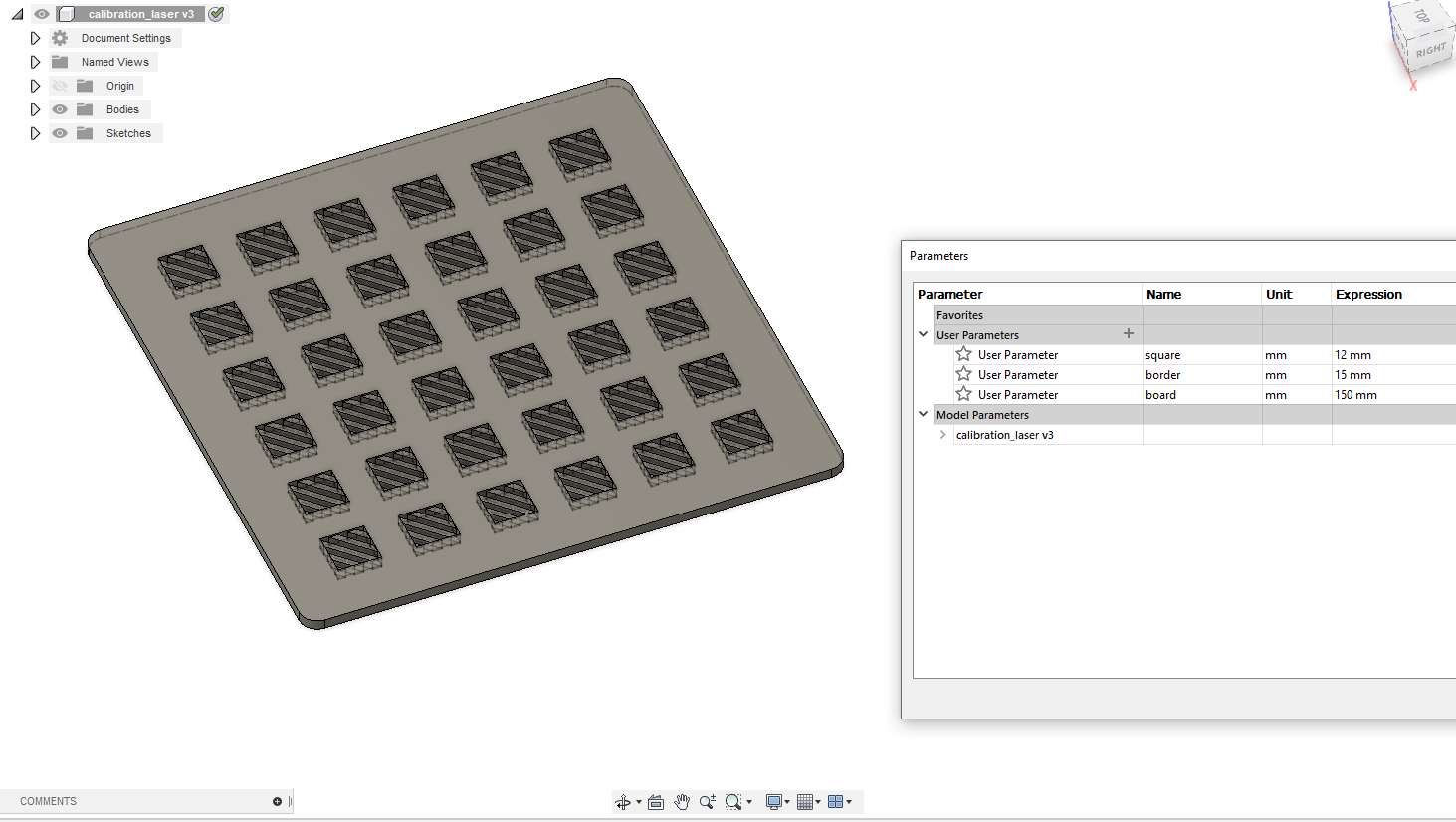
The board size is parametric, as well as the square size. Each row will contain a specific laser power, and each column is for a different speed. The driver software of our laser cutter uses colors asa way to separate different cutting layers. Therefore, every single one of these squares needs its own setting. To make the job easier, we used rainbow colors on the squares, increasing the blue component for each row, and the green component for each column. This part was done in Inkscape:
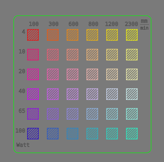
The range of speeds and power levels we picked covers almost the entire capabilities of our machine. The speed could go up to 6000 mm/min, but this might introduce shaking artifacts so we limited the speed to 2300 mm/min.
We first use our board on a 0.1mm paper sheet:
As expected, for such a thin material, we should only use low power and high speed. On the back, we can see that the only square that is not pierced is the highest speed combined with the lowest power:
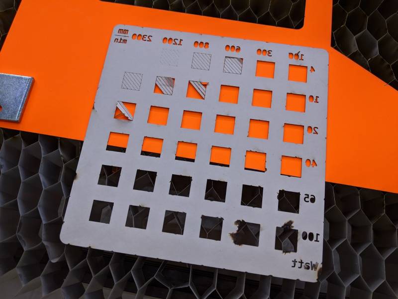
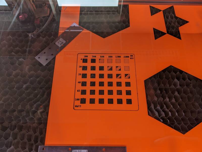
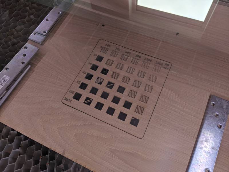
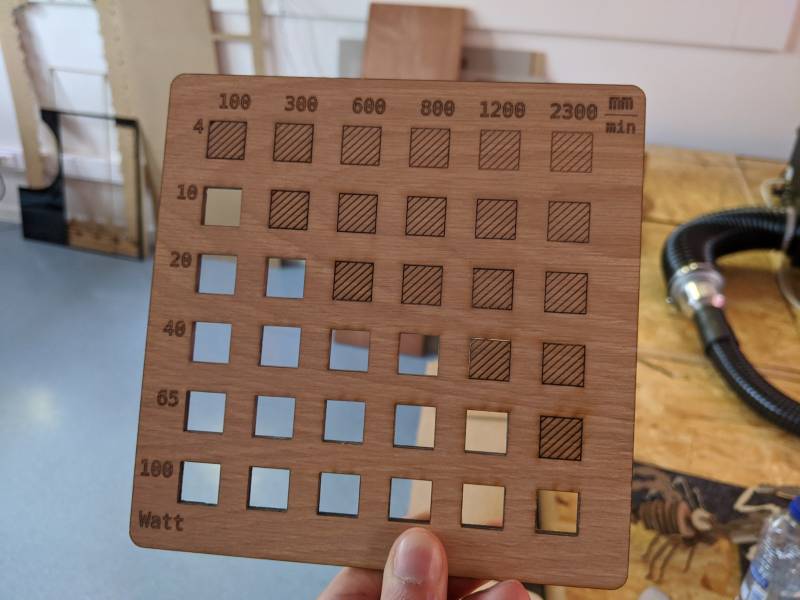
Next we tried with a sheet of 3mm plywood. The results are drastically different:
An interesting observation is the almost linear separation between the fully cut area, and the engraved area. This is a confirmation of the good linearity of the system: doubling the speed and decreasing the power by the same factor should be equivalent in terms of energy deposited per length unit. This can be explained with the following equation:
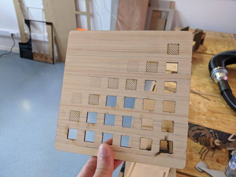
Where E_x is the energy per length unit, v the moving speed and P_{\rm laser} the laser power. As for the paper, the back of the board reveals some issues at high power.
Kerf
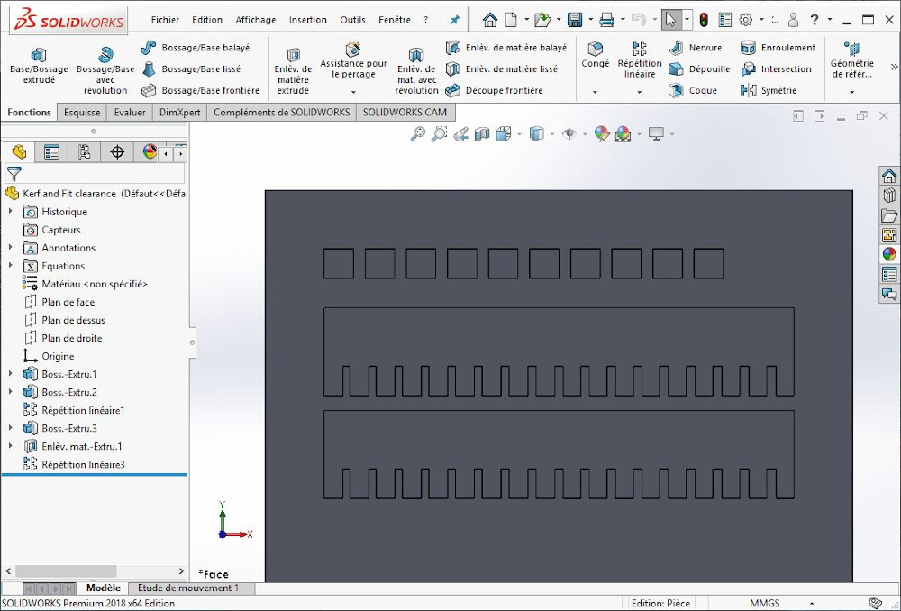
The distance between the part that is cut and the residual material is named the kerf. To measure it precisely we drew ten 1x1cm squares with SolidWorks. To measure the joint fit we also draw two comb-shapes whose slots are parametric. Their initial value starts at the middle of the comb with the thickness of the MDF sheet. This value increases by step of 0.05mm when going up and decreases of the same quantity while going down.
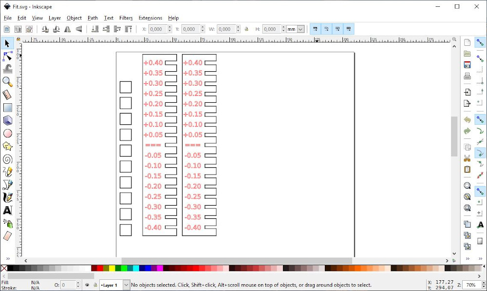
With Inkscape we added the text and prepared the file for printing. A red contour is applied on the text to enable a customization of the passes in the user-machine interface of the Lasersaur.
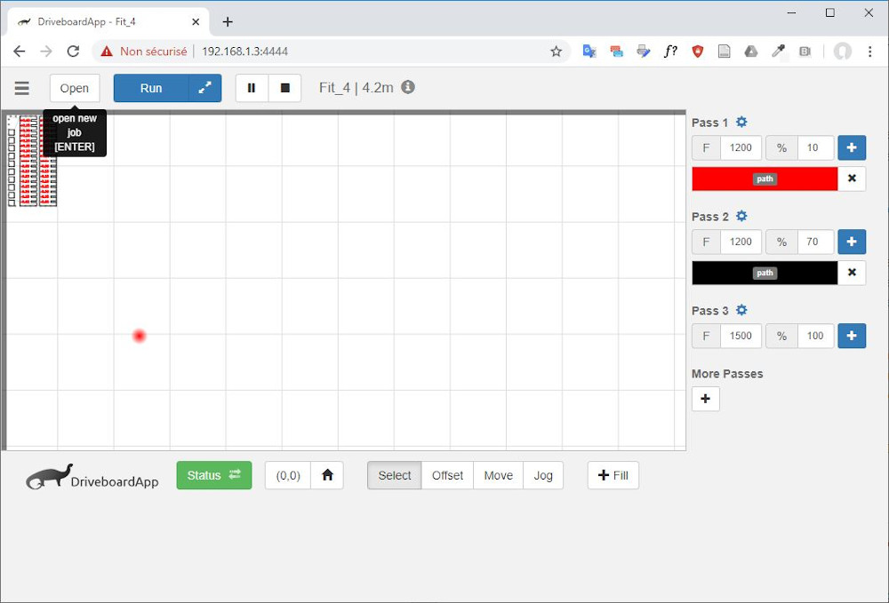
Then we used the DriverboardApp (the Lasersaur user-machine interface) to tune the power and speed of the laser with respect to the color of the drawing lines. For engraving the text (in red), we selected the color red in the right lateral bar and set the power on 10% and the speed on 1200mm/min for the first pass. As the black lines must be cut, we set the power to 70% and the same speed for pass 2. It is recommended to always make engraving first to avoid that the part moves during the engraving.
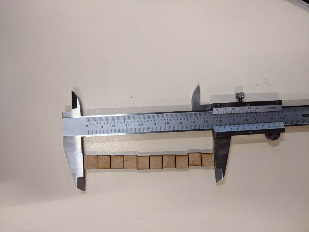
Afterwards we measured the ten squares together with a calliper and obtained a value of 98.28mm. The difference between this value and the expected measure (100mm) is equal to 1.72mm. To obtain the kerf, this value must divided by the number of squares (10). Therefore the kerf is 0.172mm.
Finally we plugged together both comb shapes. The best fit happened for a joint clearance of -0.10mm. This value will be very useful to design joints later.
