8. Computer Controlled Machining
Our assignment for this week is to make (design + mill + assemble) something big using 18mm plywood. The sheet specs are 2440x1220. The final product must be stable when assembled without using glue.
Individual Assignment
Design
First Version
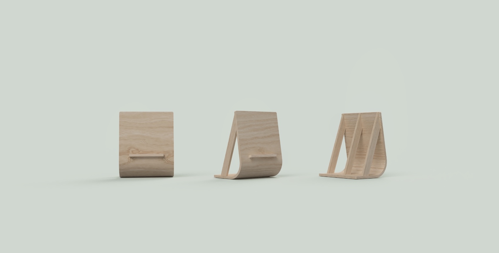
I decided to explore kerf bending to make a painting easel. I’m not familiar with working with wood and this would be a good way to get familiar with the material and Shopbot. The process of bending wood will include a lot of testing and redesigning, so I kept my concept and design simple to minimise unnecessary delays.
The first step was looking at tutorial and understanding what options I have to bend plywood. This tutorial gave a general overview, and this video helped understanding the math behind kerf bending.
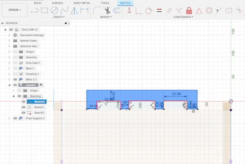
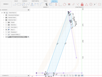
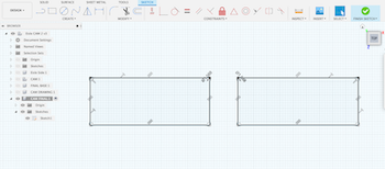
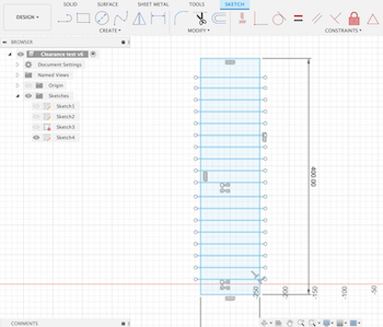
I started with he general shape I wanted, I made sure everything is parametric so I can easily adjust after testing kerf values.
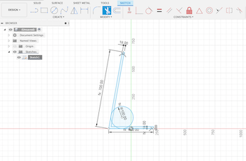
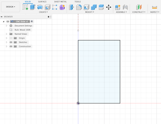
To find where the kerf cuts will be on the design, I used the sheet metal tool to simulate the design. First I designed the base of the design and extruded it. I then used the flange tool and inserted my dimensions.
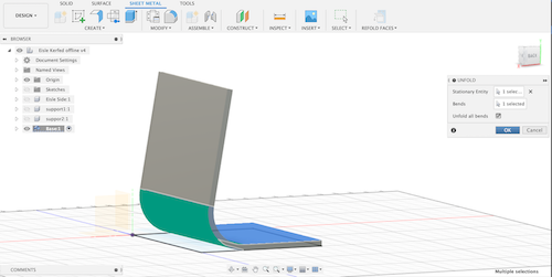
I used the fold tool to know my measurements and where to place the kerf cuts that will be plugged in at a later stage.

I then designed the stand that will hold the canvas.
I then worked on designing the easel support.
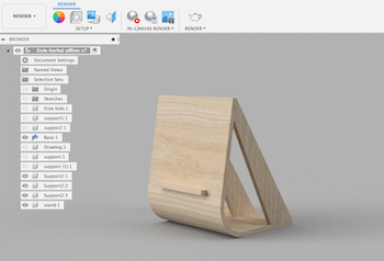
The first option is wider at the bottom, it will do a better job supporting the base and face of the design. However, I wasn’t convinced by the shape so I went back to sketching. I liked option one because it looks lighter, so I moved the support inwards and adjusted the dimensions.
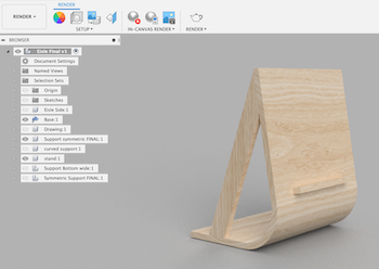
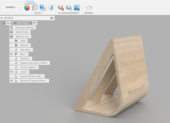
Once I had my final shape, I worked on creating the support joints and added in fillets. The fillets are important because they make the parts fit better.
Once I had all my values and final design, I copied the faces to the base I sketched earlier from the unfolded sheet. After ensuring alignment is correct, I selected each face in sketch mode, went to project/include under the create menu and selected include 3D geometry to get the sketch outline.
I added the dogbone joints, which is usually done with Vcarve. However, I wanted to do it manually as an additional test to see which would be more accurate.
Final Version
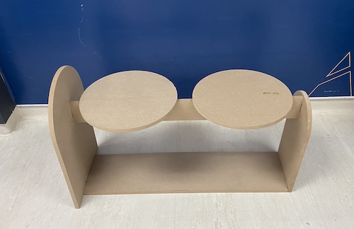
I was finally able to find a lab that had a CNC machine, it was a very long trip (and wait) but was worth it. I eventually got access to Fab Lab Jubail where they had a CNC that I could book for the day. Although I really wanted to try kerf bending, it required a lot of experimentation to get right. With the new time restriction, I decided to change my design and make bench table that can be used around the lab, and focus on the joints only (instead on both kerf bending and joints).
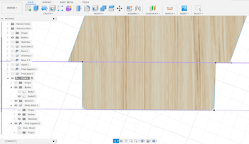
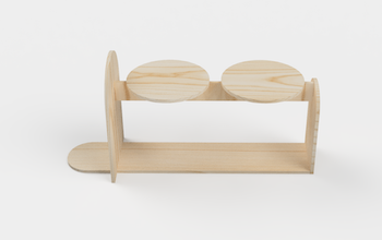
The design has two table tops that can be used as a shelf, and the bottom can be used as a storage unit. I followed the same design process as the previous version: I made everything parametric and included the clearance in joint tabs.
The horizontal support will hold the vertical side support as well as the attachment that connects the tabletop to the support shaft as seen in the image below:
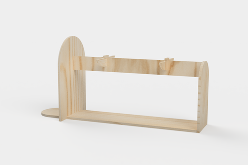
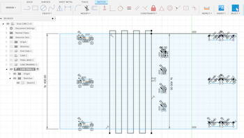
The below image shows how the shaft and base support joints are designed:
Below you can see how all parts and joints are designed:

The design process was straightforward unlike the easle design with kerf bending. for more details about that please refer to the previous section in this page.
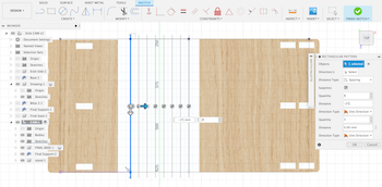
Once the design is finalized, I exported as a DXF and opened the file in Vcarve to prep for cutting. The first step was to arrange the parts to fit my dimensions. It’s important to keep it compact to fit all parts, and have some additional space for revisions or extra parts. Although I don’t have many screenshots of this process, I took pictures after to summarise the process:
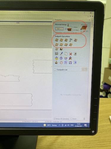
After uploading and arranging the parts in Vcarve, click on the toolpath tab on the top right. First set the material dimensions. Once inserted, go back to toolpath, and under Toolpath Operations, select 2D Profile.
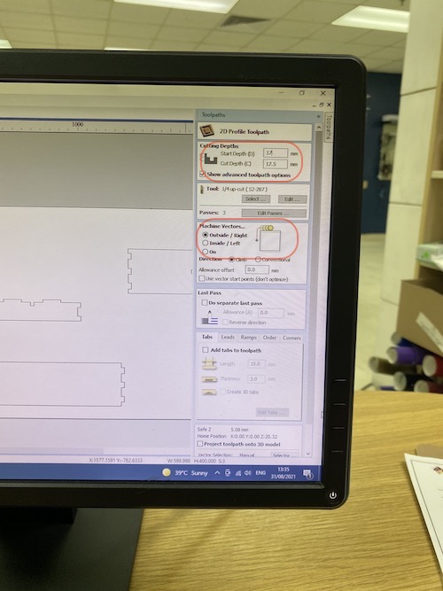
Set the cut depth, and add .5 mm to make sure it’s cut all the way through. Then select the direction of the machine bit to cut from either the outside or inside. I selected inside/left as instructed by the lab manager. Before clicking calculate and saving, make sure the bit selected is the one you will be using, I used the 1/4 up-cut bit. Once completed, Vcarve will show you the toolpath planning in 3D view as a demo, if there are no edits save the profile cut and go back to the toolpath menu to prepare the pocket toolpath (if any).
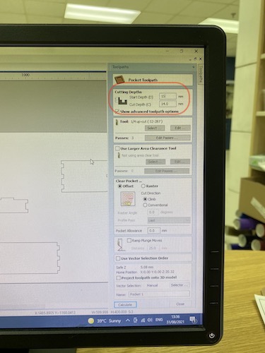
For my side support, I don’t want to cut the material all the way through so the joints and connectors don’t show. To do this, I selected pocket toolpath instead of profile toolpath from the main menu, and changed the cut depth to 16mm in the first attempt (I changed it to 15mm because the machine cut through the material). Then I repeated the same process as the profile toolpath.
Once this part is complete, I went back to the main menu and clicked save toolpath, then select the post processor to Shopbot, and click save toolpaths to generate the Gcode. The final step is to open the Gcode on Shopbot software. Using the keypad, we set the toolhead to zero the machine (the Z axis was done manually). Once everything is complete, hit cut to begin the process.
Some important safety measures are to always make sure you have a partner with you when using the CNC, if you have long hair make sure it’s out of the way, don’t stand too close to the machine during operation, and no long/loose sleeves. It’s also really loud, for safety it’s best to wear ear plugs.
Assembly
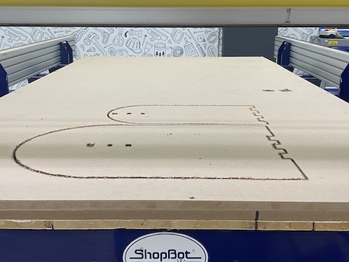
At first, it looked promising!
First issue was the pocket toolpath cutting too deep - I did not want the shaft joints to show through. I completed the cutting process to see if there will other mistakes with joint and clearance sizing.
The second error here was the joints in the base support were too big compared to the MDF thickness. It was stable, but looked wrong.
I went back to the files to check where this could’ve happened but it wasn’t clear, the Fusion files were correct and the Vcarve prep file seemed the same as to the Fusion file. Looking closer, I think I might’ve dragged parts of the design and changed the size without noticing because they were wider in size than the rest when zooming in. I adjusted the size to prepare for the second round of cutting.
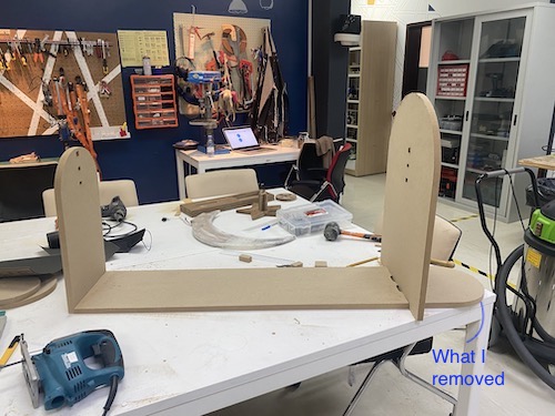
The lab unfortunately ran out of MDF, so I had to be very precise and picky about which parts to cut again. The compromise was to remove the extended part of the base support so I could fit it in and cut again (as highlighted in red in the image above).
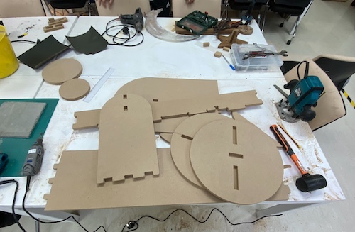
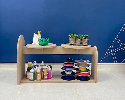
After fixing the above errors, I cut the parts again, did some sanding to clean up the parts, and assembled the table.
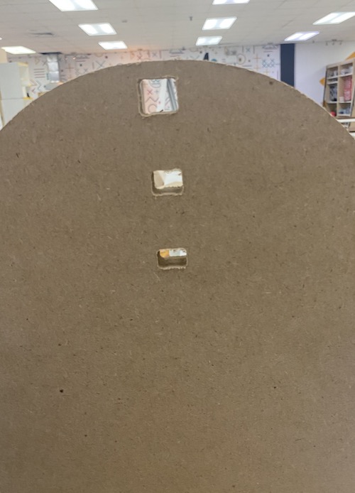
When I started assembling, I noticed that one of the joint holes in the right table top was smaller than the rest (this was an error in Fusion where I did not put in the clearance). I had to sand it manually (re-cutting was not an option because at this point there was no extra material), I tried using the sanding gun because it was taking too long, and in doing that I cut the joint hole too deep as seen in the image below.
This was not ideal, but it was a minor error that did not impact the table’s design or stability. Overall, I was very happy with the final outcome!
Final
Group Assignment
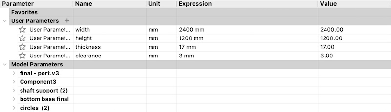
Clearance
For this week’s group assignment, I worked on testing the Shopbot clearance. To do so, I designed slots with a 0.2 mm increase in height to test the clearance value in the first design.
![]()
In the lab, the lab manager informed me that clearance they use is usually between 4-5 mm, this was too big compared to what I remember using. I was skeptical, so I tested the clearance size in both thickness + 2mm and thickness + 4 mm. The 4 mm was too big and 2mm was too small. I chose my clearance to be 3mm for the perfect fit with minimal sanding after cutting.
![]()
Kerf
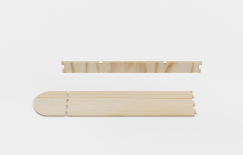
I also made a kerf test to see if my values were correct, I used an online kerf calculator and used the values generated to create a kerf bending test. The test is for 7 cuts with 16.8 mm of wood between each cut. I also tested for 8 cuts with the same dimensions to see which works better. These values and calculations were based on the first design.
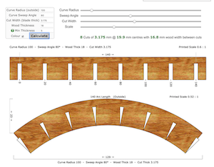
Results:
It was clear that the 8 cuts would be a closer radius as needed for the easle design to work. I still had to revise and work on kerf dimensions, however, this direction was dropped and to focus on the second design.
Please visit our lab page to see all group projects.
Reflection
I learned a lot from this week’s assignment. It was my first time working with wood, furniture, and the Shopbot. The machine was really fast and got the heavy lifting out of the way, however, I found it very hard to get a good quality finish with it. It might be the material, MDF, which was easy to cut, but it was also easy for the parts to chip or break off if the design was too thin.
I also recommend spending extra time on the clearance test and doing multiple if possible. It will depend on the person managing the machine on how they want cut and therefore calculate the clearance values, but it changes how the parts fit drastically.
Files
Test files: