15. Mechanical design
For the full project documentation, please visit our lab page.
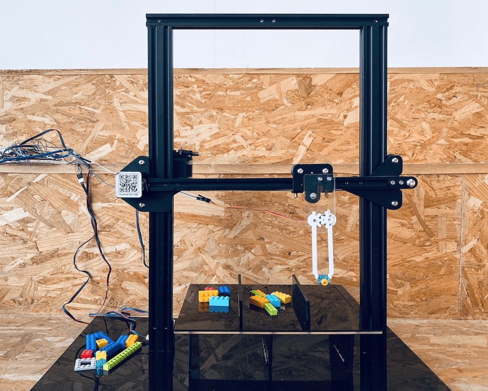
For this assignment, we designed a machine that can pick and sort LEGO bricks. The picker moves based on pre-configured coordinates to pick a brick and place it at a set compartment.
Prototype #1
We came across this idea while looking into previous projects and liked the concept. The pricker sorts the bricks using color sensors. It picks up the specified colors and places them in one compartment. We decided to proceed with the idea and enhance the structural design and support of the machine and gripper. The team that worked on this machine previously built the support after assembling the stages and without a 3D design (very brave). Their process was interesting and I learned a lot from their successes and mistakes. Moving forward, we decided to use the same cardboard stages and use them as the base of our machine specs.
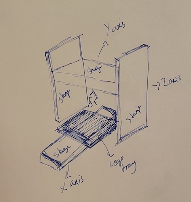
We used Nadya Peek’s cardboard stages from this website. They are axes stages that can be configured to create any kind of machine. It’s beautifully designed and fit perfectly with our concept. We wanted to have 3 axis and using these stages would simplify the design and assembly process with our limited lab access. As we progressed with design and planning, we quickly realised we had to simplify the mechanisms to be fit the time frame we had. We changed movement to be based on pre-configured coordinates to pick and place the bricks in one set compartment. We also changed to two axis (Z and Y) and stabilised the tray on the base.
Design (Shaden)
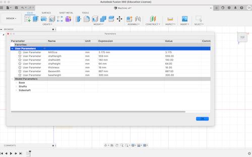
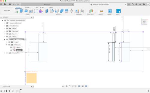
The first step was to insert the parameters based on the cardboard stage dimensions. It’s important to have a parametric model for future edits if needed
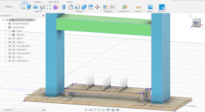
Then I designed the base of the machine which will hold the Z axis linear stages, the tray and tray support. The base, tray, and support will be made out of MDF wood 18mm wood sheets
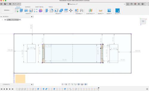
After finalizing the measurements, I started building the model, creating the joints, and adding the compartment walls (to separate the lego’s into different categories)
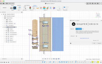
Finally, I created an additional base to be glued/bolted to the first base for extra support if needed. To export the files to .SVG, I flattened all my parts on the same plane using the align tool and exported them using shaper (go to surface > align > select a face > select a face in a plane you want the parts to be on).
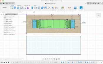
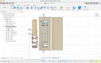
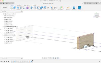
Final design:
Assembly (Munzir)
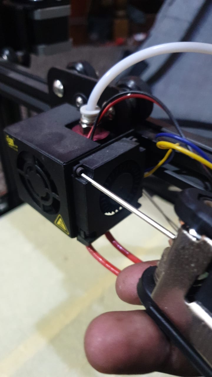
For the mechanical parts we needed, my collegue Munzir disassembled a CR3 printer and took the motor parts for our machine
The stepper motor we will be using for our machine
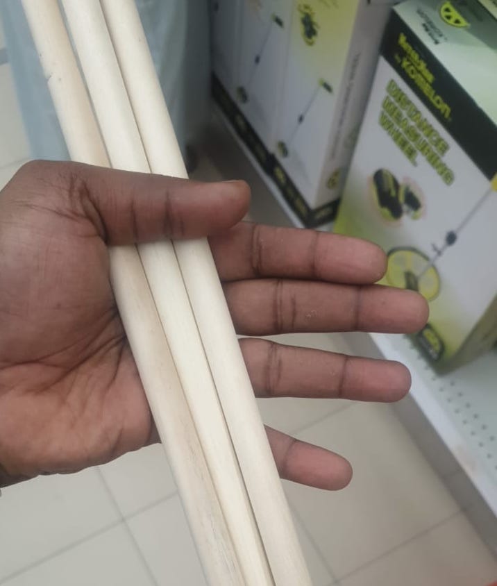
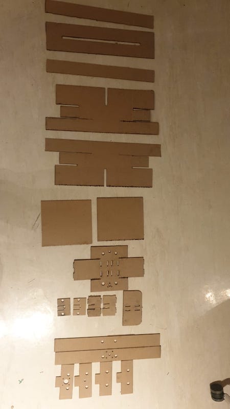
We then cut the 3mm cardboard stages using a laser cutter and 3mm cardboard. We also got support shafts from a local fabrication supply store, they we hard to find but we were lucky we found them at the last minute. Our other option would’ve been either to 3D print them or look for a machine in the lab that has the height and width we need, disassemble it, and use it.
We faced a lot of issues cutting the cardboard, unfortunately the material quality wasn’t good enough to hold the shape properly. The cutting depth was either too low or too high.
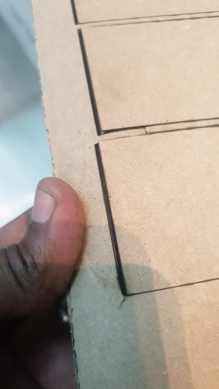
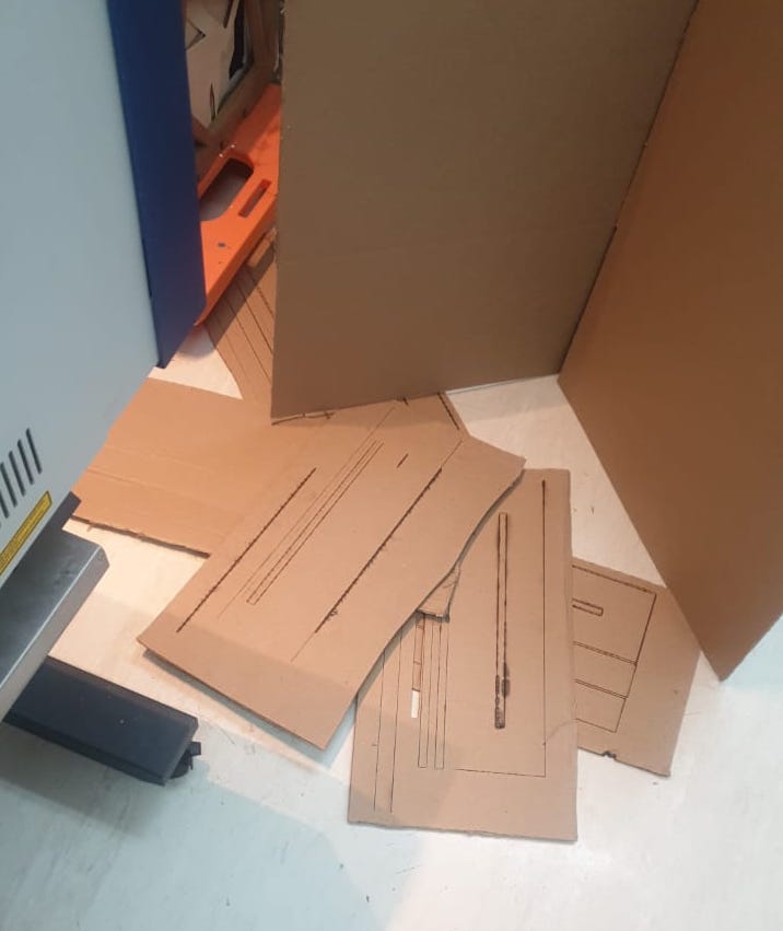
We knew the material won’t be stable after a lot of attempts, but we decided to proceed to test the mechanism manually, then go back after our presentation and adjust sizing/material
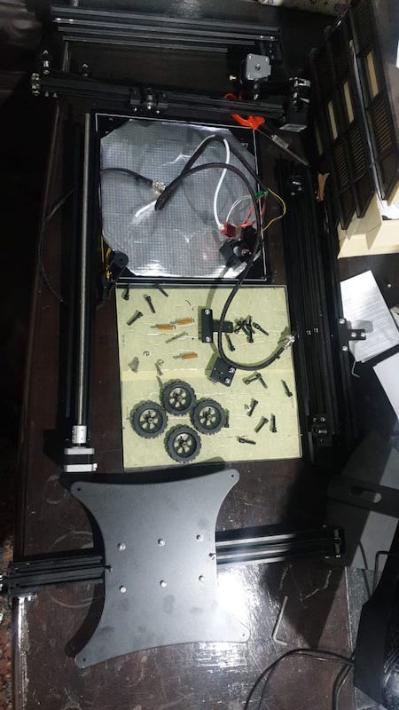
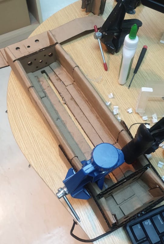
Below is the result after Munzir assembled and clamped the parts together
Prototype #2
Design (Shaden)
For our second design, we used the Z and Y frames from the disassembled CR10 printer used previously. After looking through other Machine Design projects, I found that most projects disassembled different machine parts to build the structure, and focused on designing the parts needed for the toolhead. I originally wanted to experiment with building the structure from scratch using the cardboard stages, but dropped the stages because of the difficulty of working with cardboard at the quality we were able to find.
Below is what will be used from the CR10 printer (2 stepper motors + z and y frames - the top shaft is a sample I cut to double check the placement of the screws). The electronics, base and tray design, and toolhead were created by Munzir and I respectively.
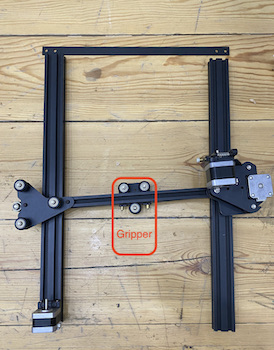
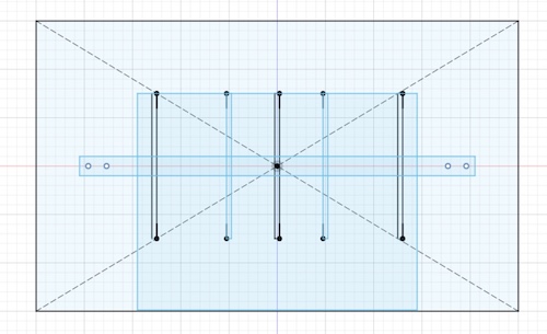
The base, tray, tray support, tray separators, and top shaft (extra, incase we need it for stability) will be designed based on the frame specs.
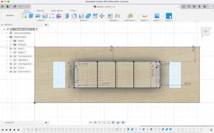
The tray, support, and separators will have the same design with the only adjustment being to the base size. The CR10 frames are much smaller so we reduced the base size as well (220x300mm). The most important part of the base was ensuring the bolt holes are at the exact same place as the z+y frames and the top shaft. As for the tray, I extended the front to be parallel with the base, this is because the gripper is not centered on the tray, if I left it as it was previously the gripper will not be over the tray (see assembly below).
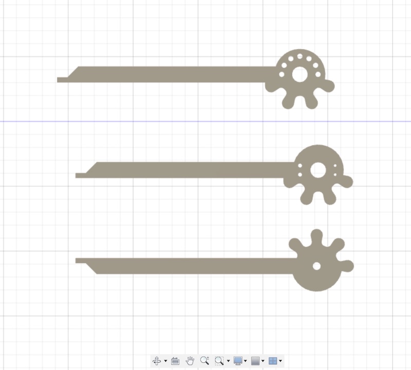
As for the gripper, we used the same base design used previously. The original design:
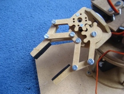
Looking at the gripper, we didn’t really need all of those parts. To minimize, we will only be using the gripper arm to pick up the lego pieces, and the plate connector to attach the motor and gripper to the frame.
The first step was to increase the size of the gripper arm to 90mm so it’s long enough to pick up the lego.
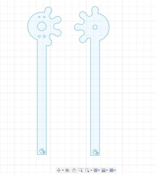
I then added a 8x8mm plate for a better grip
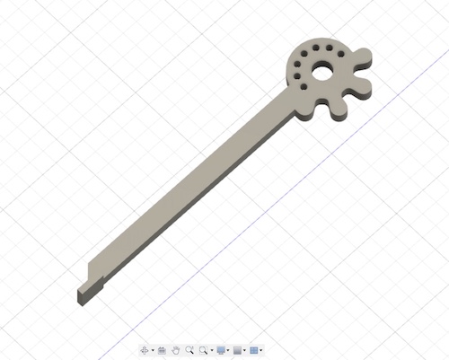
The gripper arm will be attached to the motor. The original design had small bolt holes, I deleted them, created 2mm circles around the head so it can fit the screws we’ll be using.
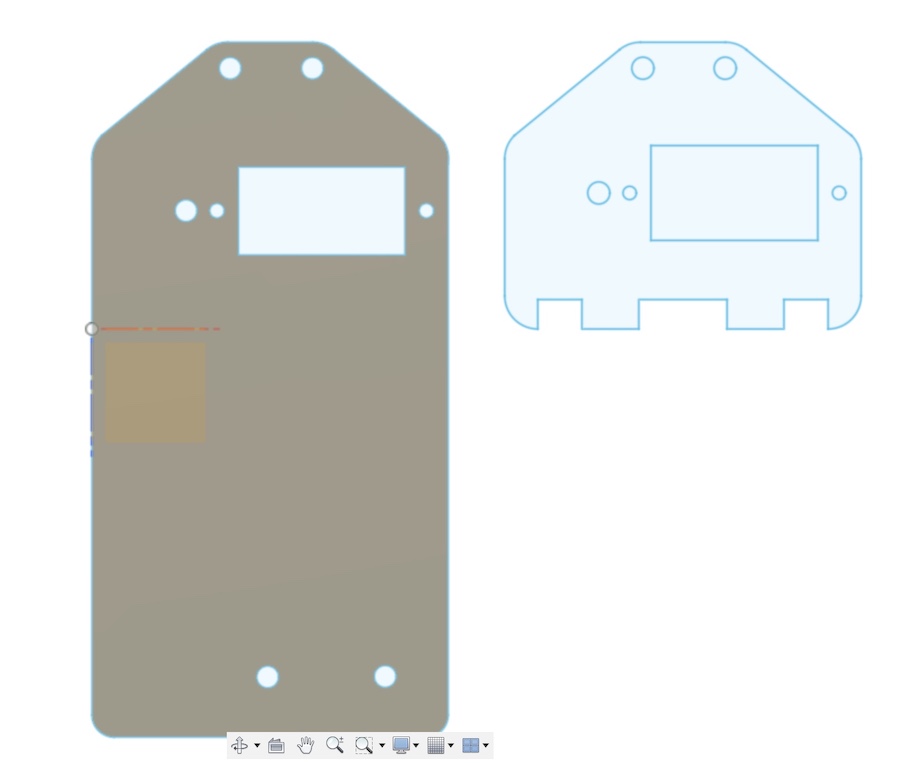
As for the plate connector, I increased the size to be 100mm and added 3mm bolt holes so I can attach it to the frame.
Assembly (Shaden)
Gripper:
After printing the design, I attached it to the motor by first attaching the plastic plate that comes with the servo to the motor. Then I screwed the bolts to the plate and made sure the motor is securely attached to the plate by using glue.
As for the second arm, it was screwed in using a long 3mm screw and secured with a hex.
Connector plate:
I used the Full Spectrum laser cutter to cut the design in 3mm acrylic sheets. I was lucky enough it worked from the first time!
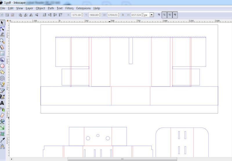
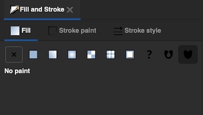
I exported the file as an .SVG from Fusion and opened it in Ink Scape. I changed the fill settings (under the object menu) to no fill
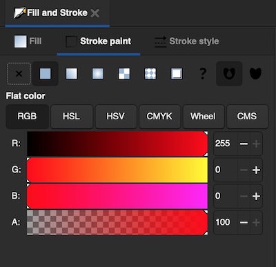
Stroke paint to red RGB 255
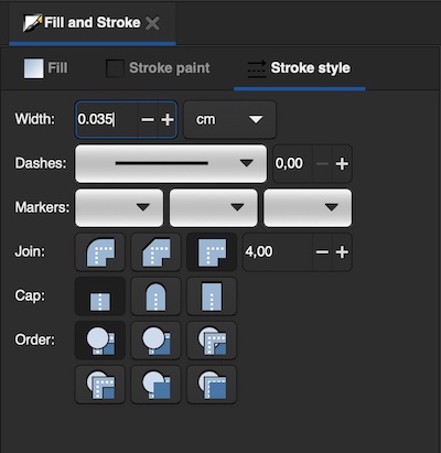
and stroke width to 0.035
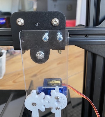
After the piece was ready, I attached it the frame using 3mm screws.
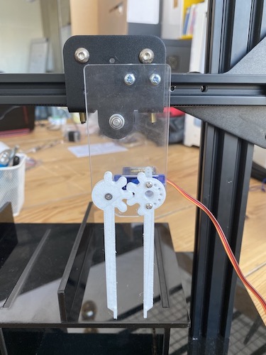
MAchine Assembly:
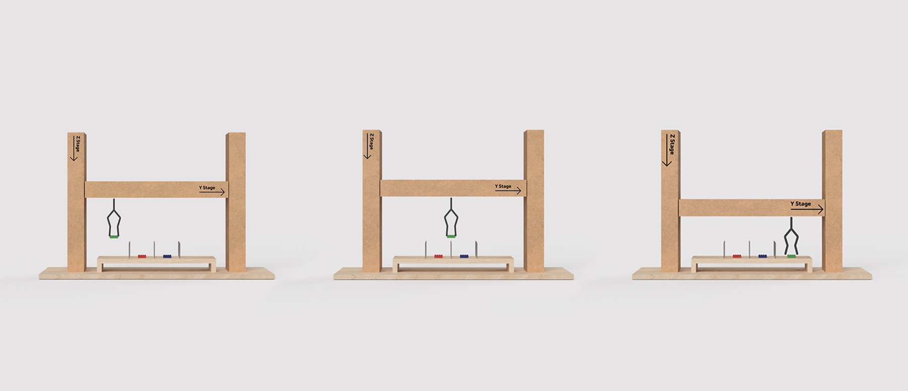
Manual test:
Electronics (Munzir)
Please visit Munzir’s page.
Final
Learning Outcomes
-
The way we decided to plan the design, assembly, and electronics of the machine was very linear. It would’ve been better if we had planned this to be a more iterative non-linear process to avoid running into issues that were hard to resolve due to time constraints towards the end.
-
I underestimated the amount of wires we would have! It was hard to move the machine around because the wires and electronic components were moving and disconnecting. Moving forward, keeping in mind where the electronic parts will be placed will be considered at an earlier stage.
-
I plan on using the cardboard stages in the near future. Sourcing good quality cardboard will be tricky but worth the effort. They’re beautifully designed for “cheap and cheerful” machine prototypes and give a lot of flexibility with what kind of machine I can make. Because they were simplified, it made it easier for to understand the mechanics behind axes and how to operate them. This accelerated the learning process for this project, and moving forward, I’m excited to use them to make a more complex machine.