4. Computer controlled cutting
Group assignment
- Characterize your lasercutter’s focus, power, speed, rate, kerf, and joint clearance
- Document your work (individually or in group)
The members of the group:
- Achille
- Anssi
- Jari
- Hannu
Individual assignments
- Cut something on the vinylcutter
- Design, lasercut, and document a parametric construction kit, accounting for the lasercutter kerf, which can be assembled in multiple ways,
- …and for extra credit include elements that aren’t flat
Ideas
Shortly:
I decided to vinylcut star figure.
Lasercutting assegnment was very hard to start. It was difficult to generate an idea of a parametric construction kit. So, I consulted with staff of Fab Lab and my student friend.
Plan to workflow
Research
- What means vinyl cutting
- What means laser cutting
- What means parametric design
- Safety at work
Vinylcutting
- Design of figure
- Cutting process
Lasercutting
- Generate an idea of a parametric construction kit
- Design of part of construction kit
- Cutting process
- Assembly of construction kit
Conclusion
Research
Cutting is one of manufacturing process, which separate physical objects from raw material. Vinyl cutting means that Cutter cuts out shapes and letters from sheets of thin vinyl. Laser cutting means that laser ray cuts out shapes from raw material.
Vinyl cutting
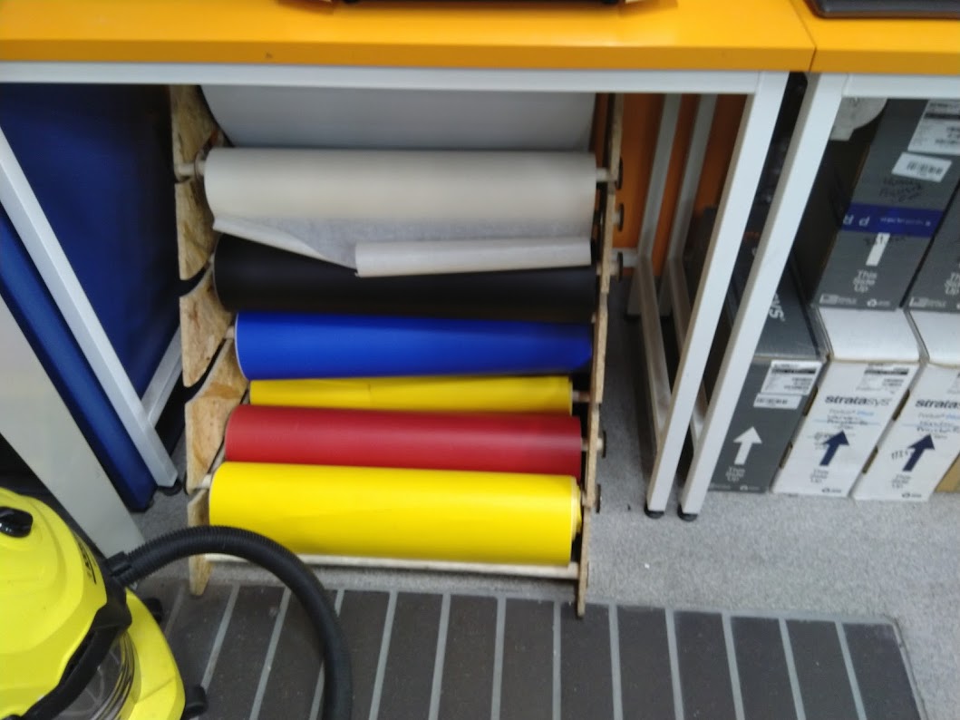
The chemical name of Vinyl (polyvinyl) is Polyvinyl chloride (PVC). In the picture Stock of vinyls in Fab Lab Oulu.
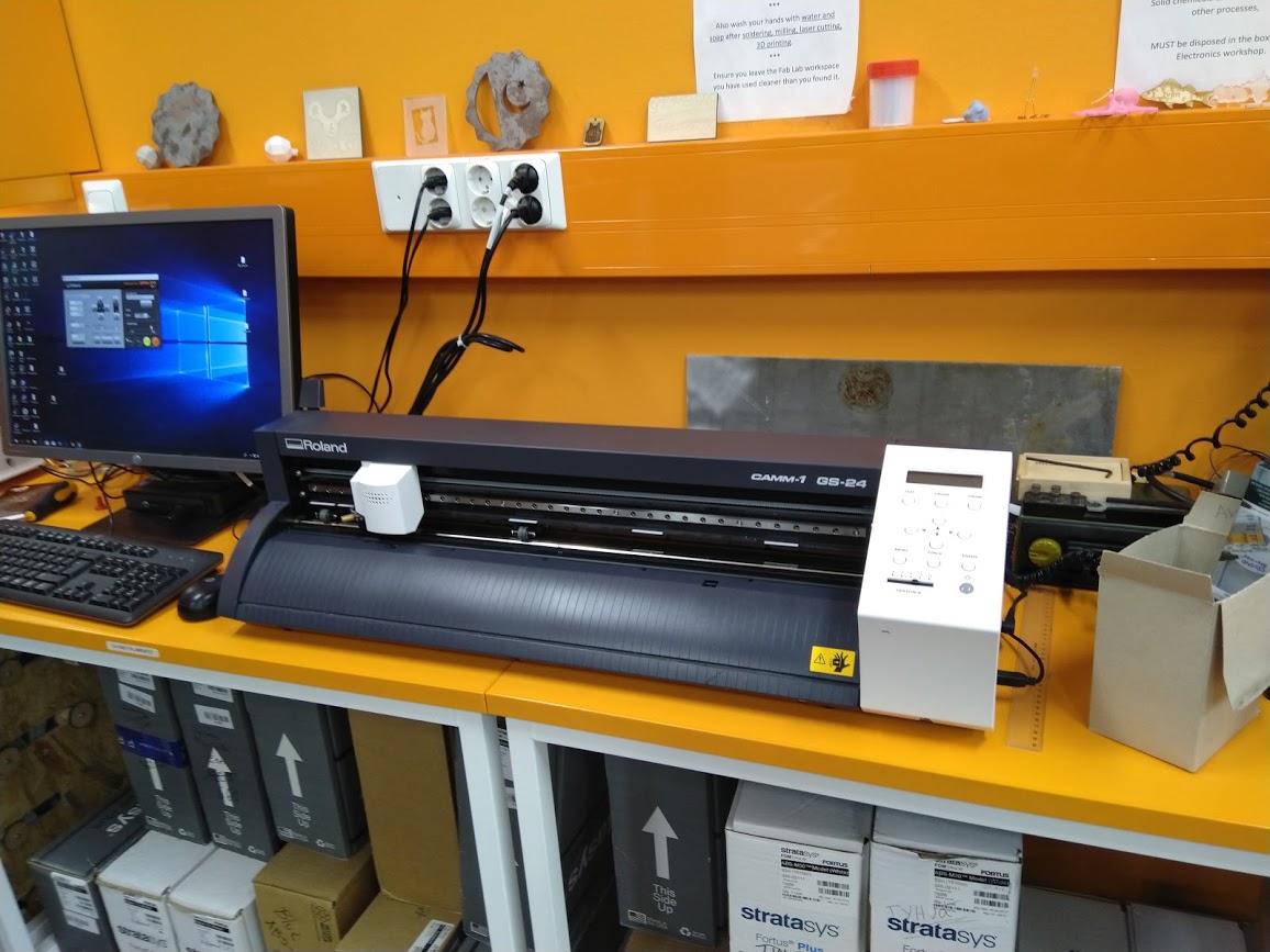
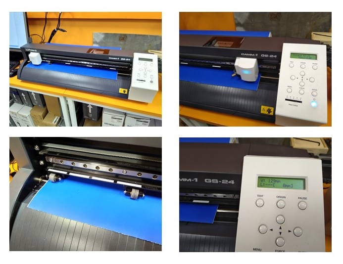
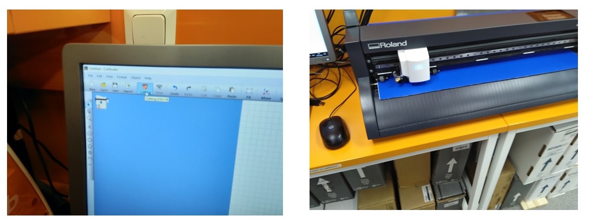
Vinyl cutting stations in Fab Lab Oulu consists of vinyl cutter Roland camm-1 gs-24, PC and cutting software Roland Cut Studio in PC.
To cut out a figure, a figure have to be in vector graphics format. It is not nesessary to design a figure in vector graphics format. Is possible design a figure in other formats at beginning and at last, when a figure is ready, to convert to vector graphics format by some software.
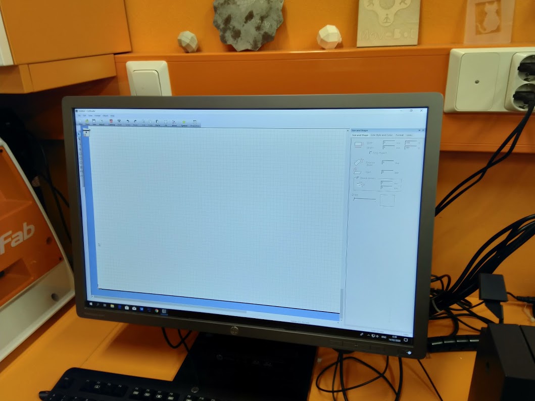
Roland Cut Studio
Roland Cut Studio, which converts, if necessary, a design to vector graphics format.
Open/Import/Export (ai, eps, bmp, jpg, stx)
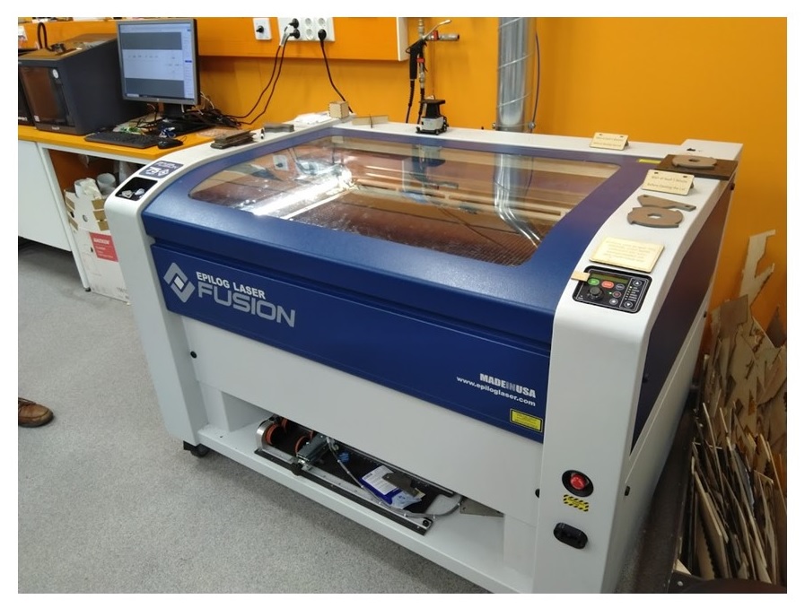
Laser cutting
Laser cutting station
https://ehs.mit.edu/workplace-safety-program/laser-cutter-safety/
Parametric design
I trained parametric design in these videos
https://www.youtube.com/embed/ISGSUHCexWc
https://www.youtube.com/embed/OBzcdgaa0n8
Vinylcutting
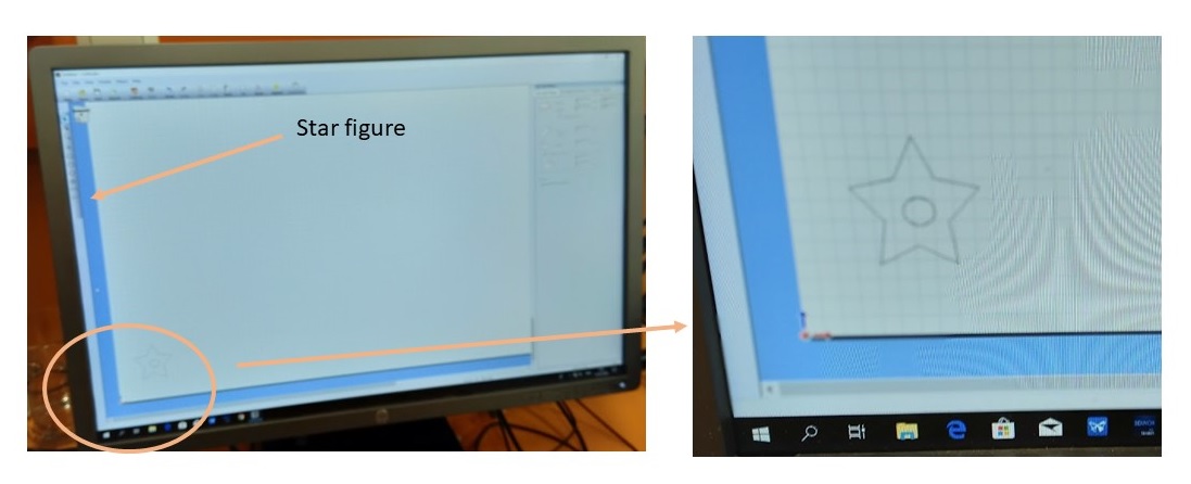
I decided to use Roland Cut Studio also for designing, not only to cut figure
Designing
I decided to design my star figure by using Roland Cut Studio:
I just picked star figure from left side tool bar, resized it and placed it right position on sheet to the bottom left. Cutting data was ready to cutting.
Some my student friends designed a figure by using other design program such as inkscape
Cutting
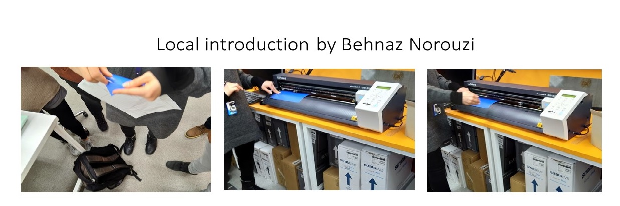
First I set cutter to wait cutting data.
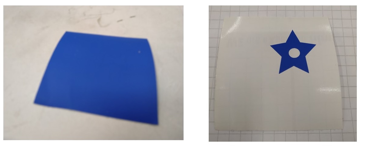
- I chose material from Stock of vinyls and placed it to behind cutter.
- I fed vinyl to by the back way to through cutting area.
- I placed pinch rollers onto left and right edges on your cutting area. That pinch rollers I set beside white grit marks.
- Then I turn on cutter.
- I selected roll and pressed enter button. Then cutter measure width.
- I moved blade to right position by using arrow buttons and then I set position by pressing and holding position button.
Then checked cut settings such as size of sheet and blade position on cutter.
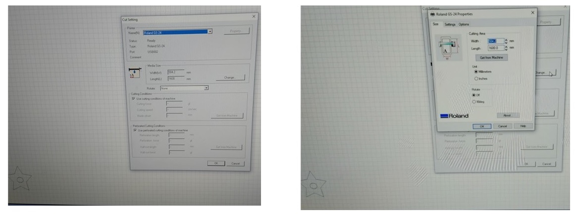
At last it was time to cutting. I started cutting to choose cutting tool from ribbon. Then I pressed OK button and cutting started. Cutting was running smoothly.
When cutter stop to cutting. I got just piece of vinyl. I started to peel that piece by using tweezers hook…then suddenly star was born.
Lasercutting
Generate an idea of a parametric construction kit
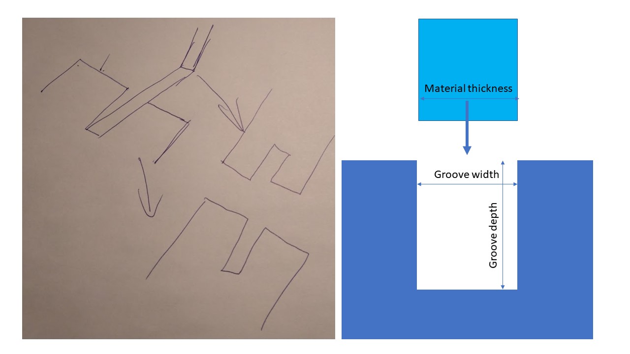
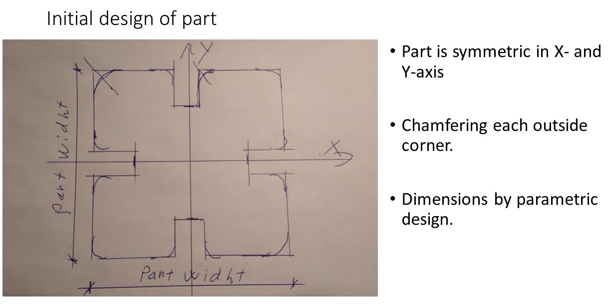
The first of all I explored sites of Fab Academy and discussed with my student friends in Fab Lab. Then I made my initial design to part of construction kit. Essential question was, how to connect parts to each other? So, I decided to make groove to connect part to each other.
I tried to all requirements for part in initial design. Dimensions of part took notice of kerf in designing. I calculated cutting data to using in parametric design.
Design of part of construction kit
This was first time when I use FreeCAD software.
“FreeCAD is an open-source parametric 3D modeler made primarily to design real-life objects of any size. Parametric modeling allows you to easily modify your design by going back into your model history and changing its parameters.”https://www.freecadweb.org/
Step 1:
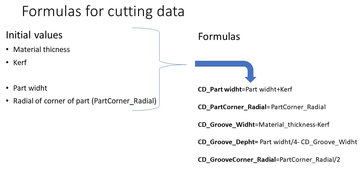
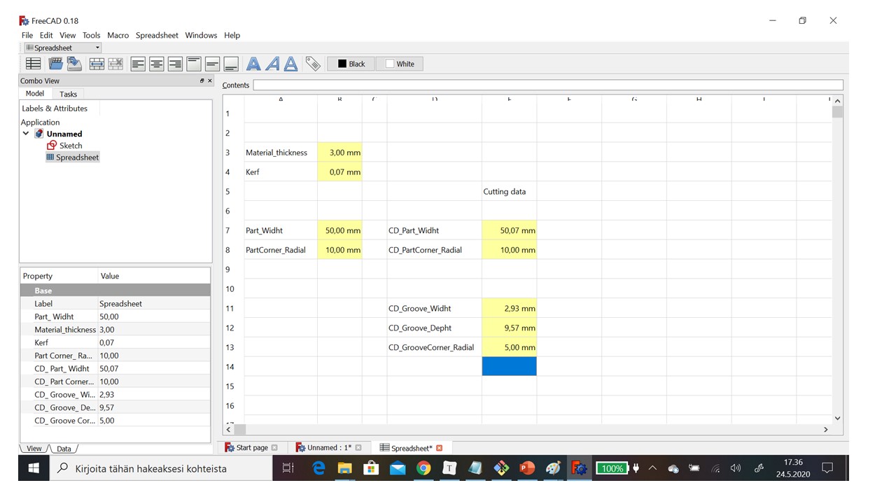
So, I determined cutting data for part in spreadsheet. You can see that cutting data is calculated based on initial values such as material thickness, kerf, part widht and radial of corner.
Step 2:
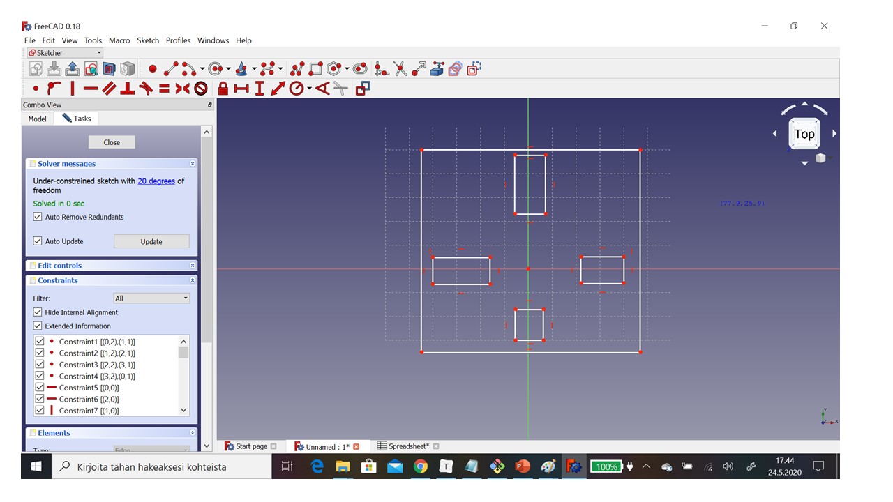
When cutting data was ready in Spreadsheet I started design part coarse geometry.
- I chose Sketcher workbench
- I started new sketch by pressing Create new sketch.
- Then I decided sketch orientation by chose XY-Plane and I got grid.
- First I drew outlines of part (big rectangle).
- I pressed Create new rectangle in the sketch (R).
- I pointed first point to the bottom left and next to the above right
- Then I I drew outlines of grooves (four small rectangles) same way as 4.
Step 3:
When initial geometry was ready I made chamfers at the corners and grooves by constraints.
-
First I tied groove rectangles to part rectangle by using constraint feature
-
I chose Fix a point onto an object (Shift+O)
-
I chose point of groove and then line of part.
-
Then I cut part lines by using Trim an edge with respect to the picked position (T, R)
-
I picked that part of line what I wanted remove.
-
Then I made fillets to corners by using Greate a fillet between two lines or at coincident point (F). At the corner I pointed both lines and I got curve.
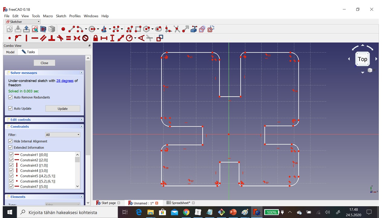
Step 4:
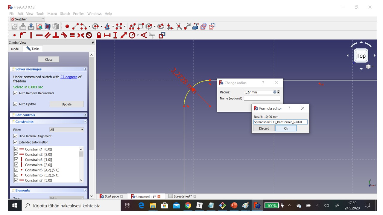
Now it was time to give dimensions for details of parts. In the picture you can see that I linked radius of corner to spreadsheet value Spreadsheet.CD_PartCorner_Radial. I used same method to define all dimensions of part.
-
First I defined radius of corners
-
I chose Constrain an arc or a circle.
- I pointed curve. Then I got Change radius box.
- I chose from raidus line fx symbol. The I go Formula editor.
-
Now I gave name of parmameter in spreadsheet by typing Spreadsheet.CD_PartCorner_Radial.
-
Then I defined similarly horizontal and vertical distances by using Fix the Horizontal distance between two point or line ends (Shift+H) and Fix the Vertical distance between two point or line ends (Shift+V)
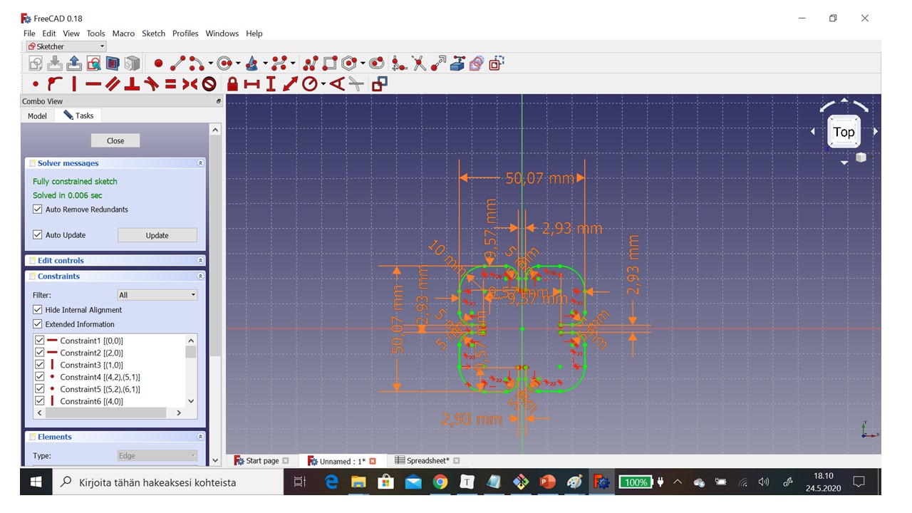
Step 5:
Result of defining constraints.
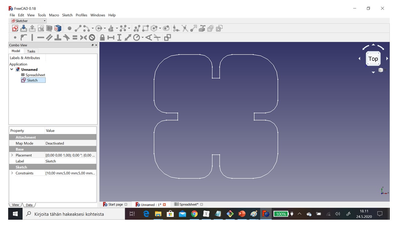
Step 6:
Now we have cutting data. I export this sketch to pdf format.
Cutting process
First of all safety instructions when you working with laser cutter.
- Follow local and universal instructions.
- If you are not sure ask first.
- Note that ventilaiton is on during cutting process
- Use only accepted materials. Not shining material for example mirror or steel,
- Watch over cutting process. It is possible that material start to burning.
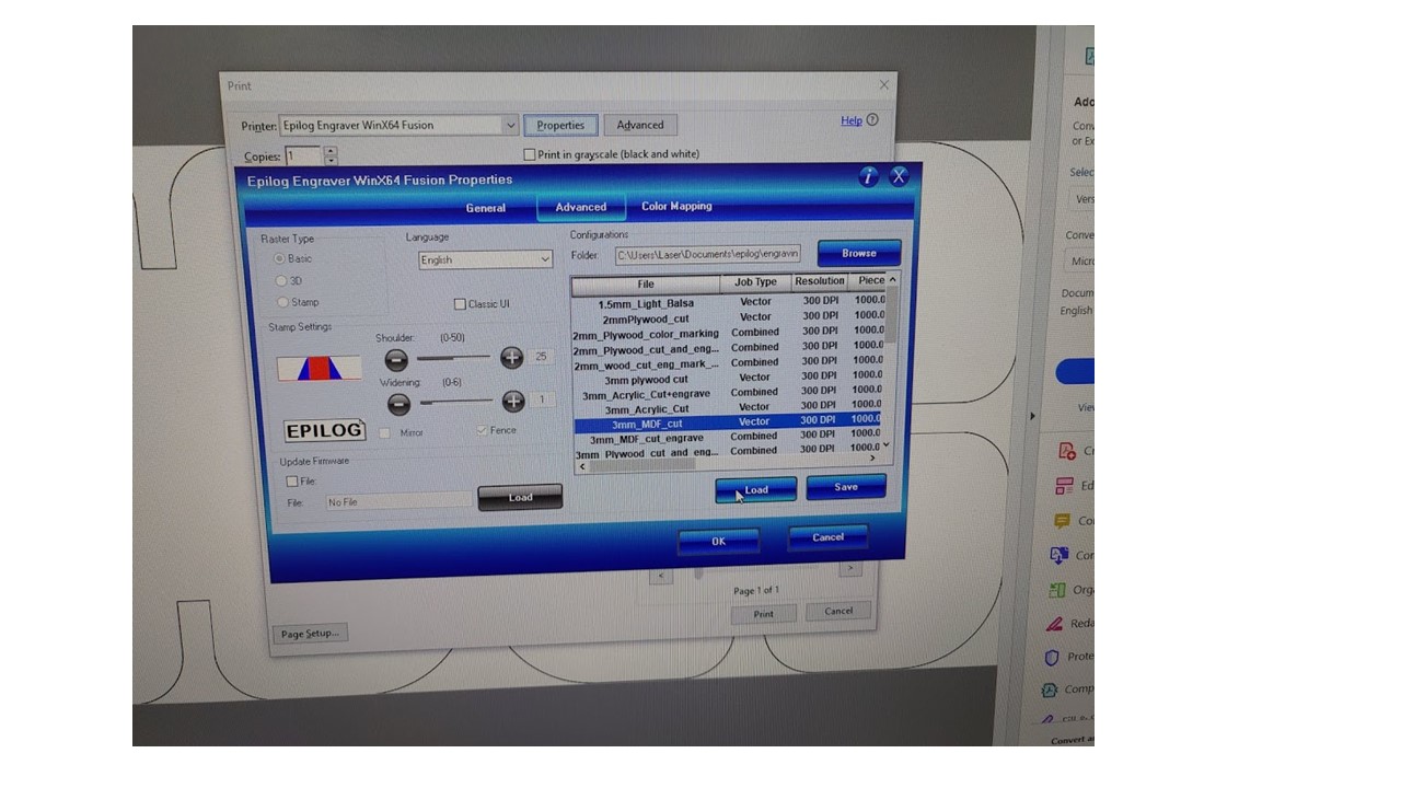
I open my cutting data file in PC of laser cutting station with Inkscape to edit line width 0.02mm. After that I
opened file with Adobe reader to cutting part.
- I chose Print
- I picked to printer Epilog Engrave Winx64 Fusion
- I cheked Properties. I chose right material file 3mm_MDF_Cut and loaded it.
- Then I sent cutting data to laser cutter to press print button.
Before cutting process we adadjusted laser ray to right distance from material. We use measure instrument for that.
- First we rised laser head up
- We put measure instrument to laser head
- Then we drove laser head slowly down
- When the measure instument touched material then distance was right
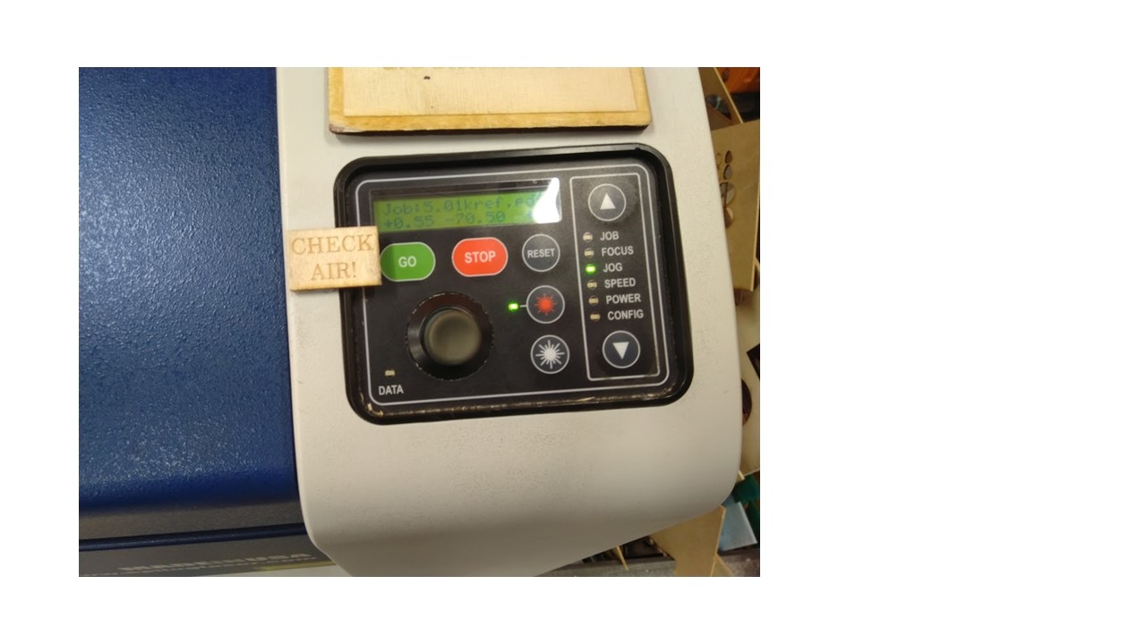
When cutting data was sent to laser cutter it was time to operated cutter. First I chosed my Job (cutting data). Then I moved laser to right position by using jog. I checked that ventilation was on and after that I started cutting by push button Go. Cutting process was successful. I got four perfect parts to my construction kit. I tested that it was easy connect parts to each other. After testing I cut more part.
Assembly of construction kit
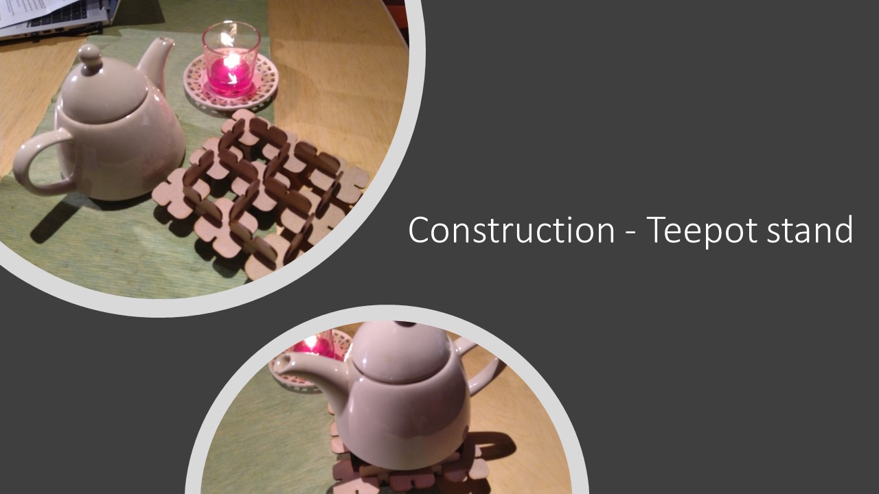
I assembled teepot stand by using 21 parts.
Construction - Teepot stand
Conclusion
- First of all it was nice to see how powefull parametric design is.
- I was happy with my laser cutting project.
Files
Vinyl cutting file:
Laser cutting file:
.FCStd file for ConstructionKitPart
.STL file for ConstructionKitPart
Useful links
- Fab Academy tutorials
- https://en.wikipedia.org/wiki/Vinyl_cutter
- Roland Cut Studio - Introduction - Video 1
- Roland Cut Studio - Importing a JPG - Video 2