9. Embedded programming
Reguirements
Group project
compare the performance and development workflows for other architectures
Individual project
read a microcontroller data sheet program your board to do something, with as many different programming languages and programming environments as possible
Individual project
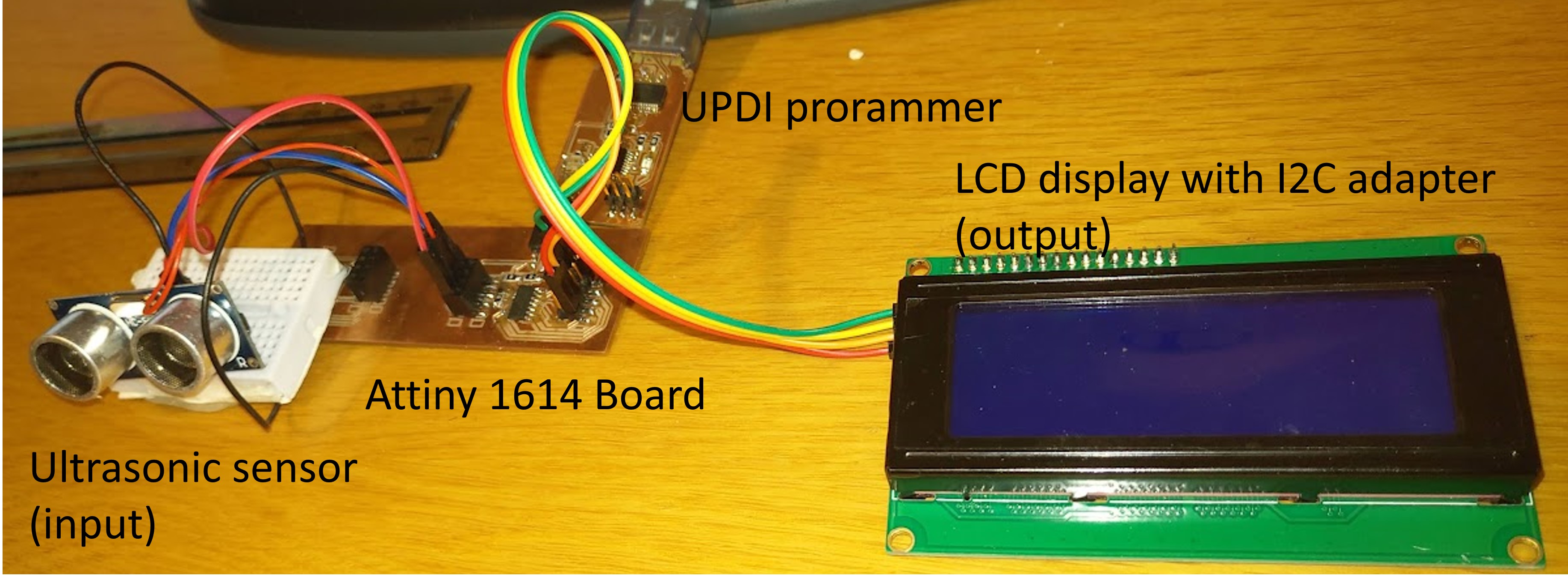
On this week I use my Final project board (version 2) On that board I have used ATtiny1614 microcontroller. On this week I have connected Ultrasonic sensor and LCD display to that board. I have documented Ultrasonic sensor on 10. Input devices week and LCD display on 12. Output devices week. On this week I show coding process.
Research
I have already used some microcontrollers on my boards such us:
- Electronics production week: ATmega328P (UPDI programmer)
- Electronics design week: ATtiny 412 (Echo board)
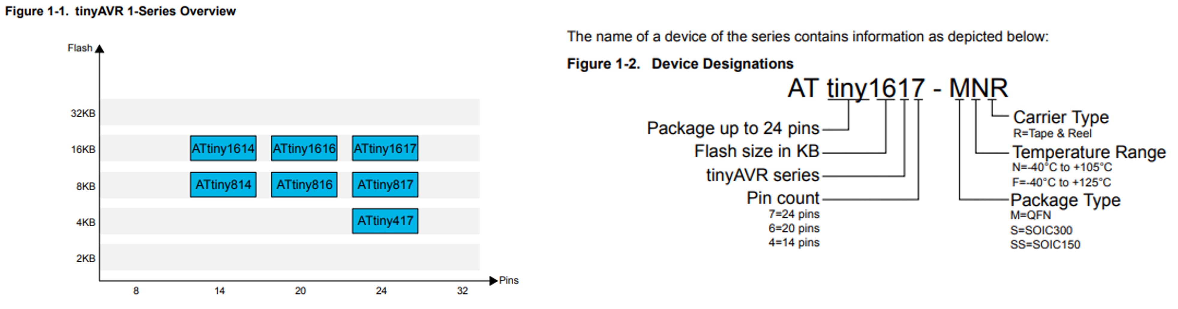
But now I introduce my final project microcontroller ATtiny1614 (Flash memory 16 kB and 14 pins).
Some Features and Parametrics of ATtiny 1614:
- Single pin programming and debugging interface (UPDI)
- 8-bit Digital to Analog Converter (DAC)
- SPI / I2C / USART
- 16 pins
- Program Memory Type: Flash
- Program Memory Size 16 KB
- CPU Speed (MIPS/DMIPS): 20 MHz
- Data EEPROM: 256 bytes
- Temperature Range Min: - 40 Celsius
- Temperature Range Max: + 125 Celsius
- Operation Voltage Max.: 5.5 V
- Operation Voltage Min.: 1.8 V
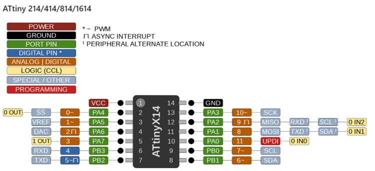
The pinout of ATtiny1614
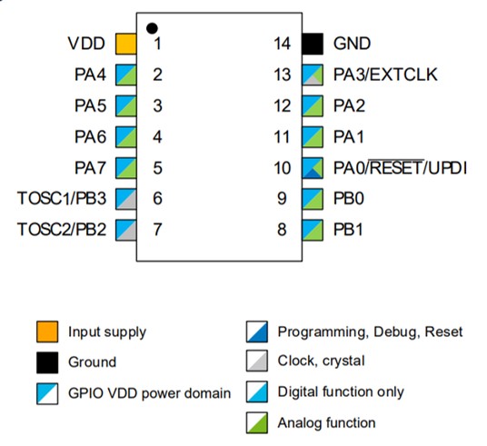
The pinout of ATtiny1614 is
Block Diagram
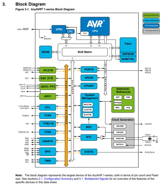
ATtiny1614/1616/1617 Data Sheet
UPDI
In ATtiny 1614 has one pin for UPDI (Unifield Program and Debug Interface). UPDI is an proprietary interface for external programming and on-chip debugging of a device. I fabricated my own UPDI programmer in week Electronics productions.
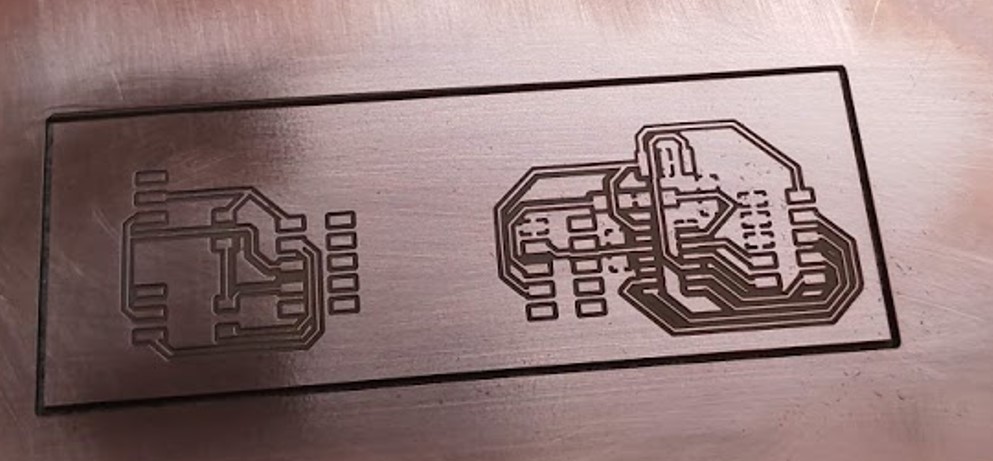
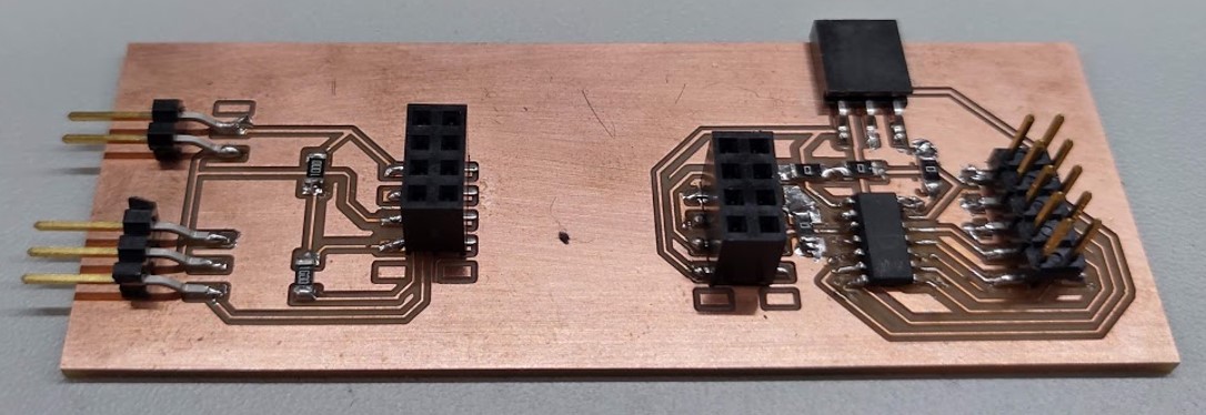
Board
I fabricated two board version in Final project. Now I use version 2. Now I use only right side of board. There are connetions to sensors (input) and display (output).
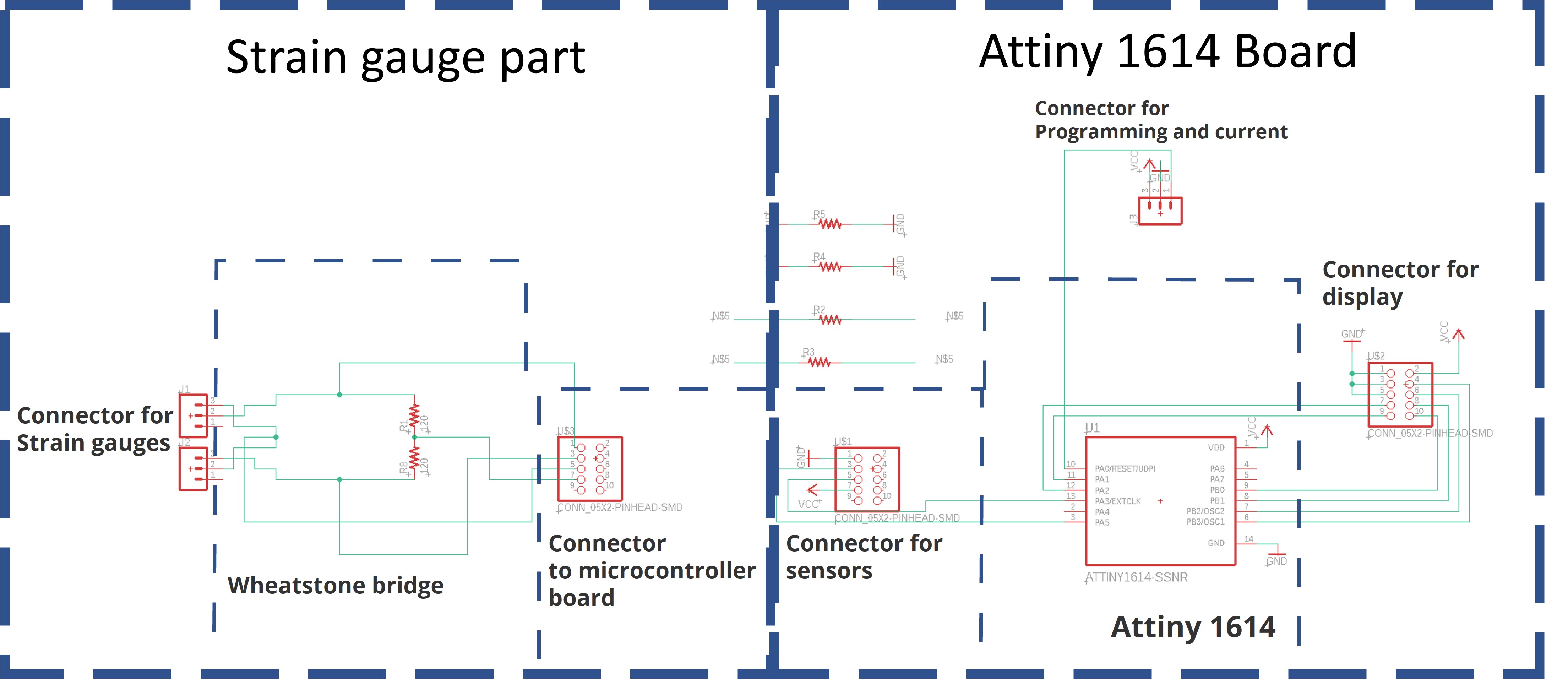
The pinout of my board
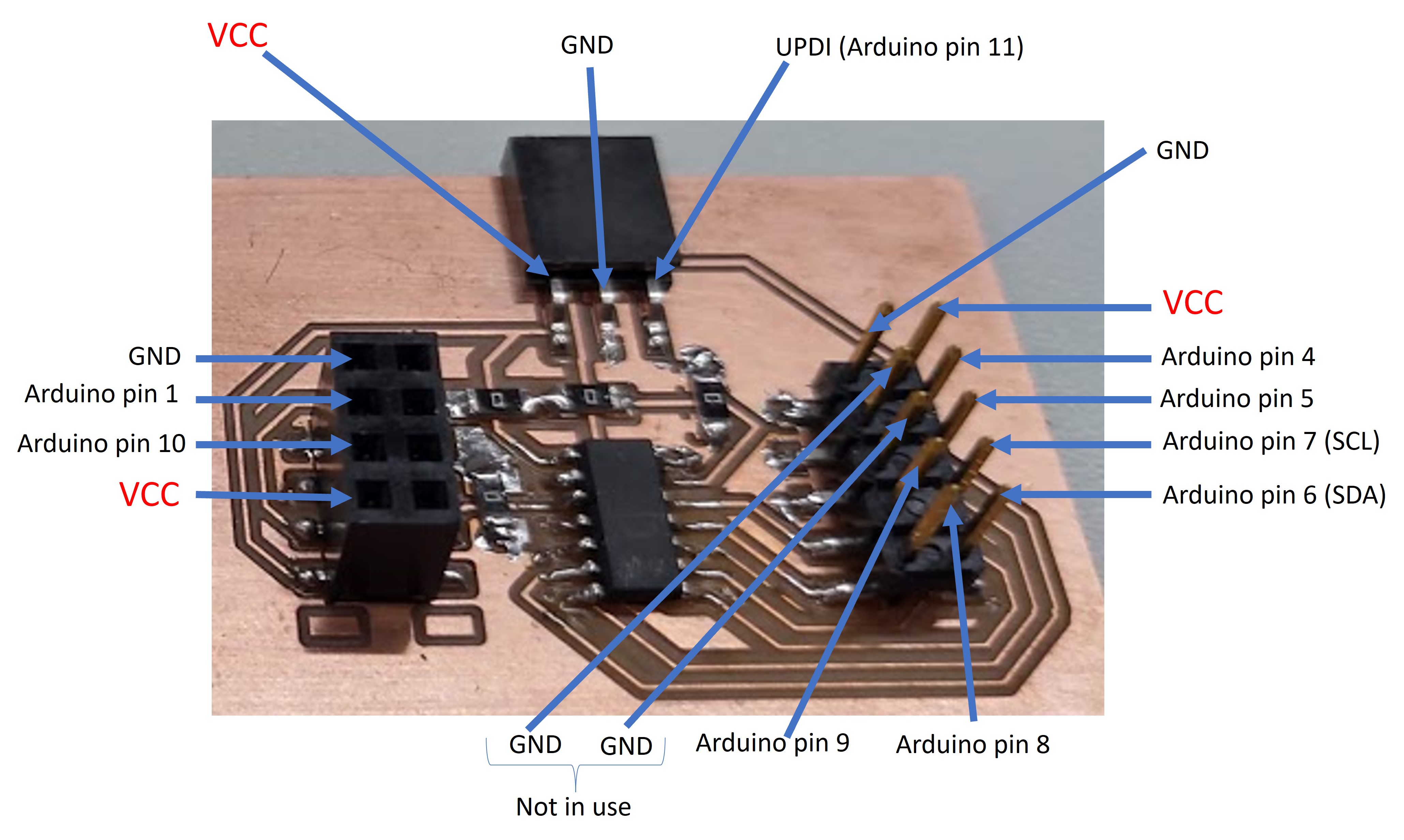
Input and output devices conneted to ATtiny 1614 board
Programming
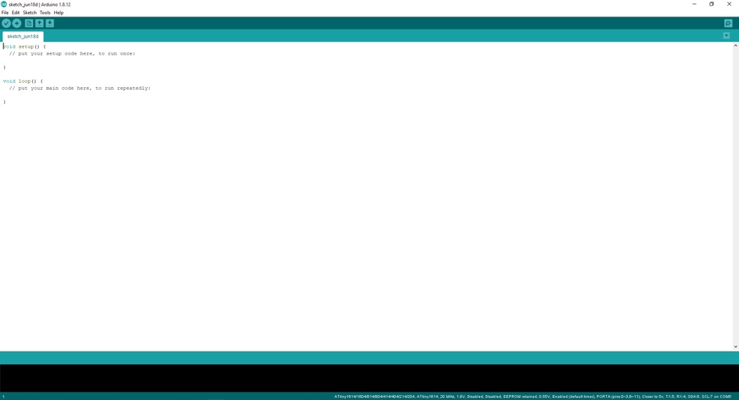
Step 1. I started programmin to open Arduino IDE. I open new programmin project.
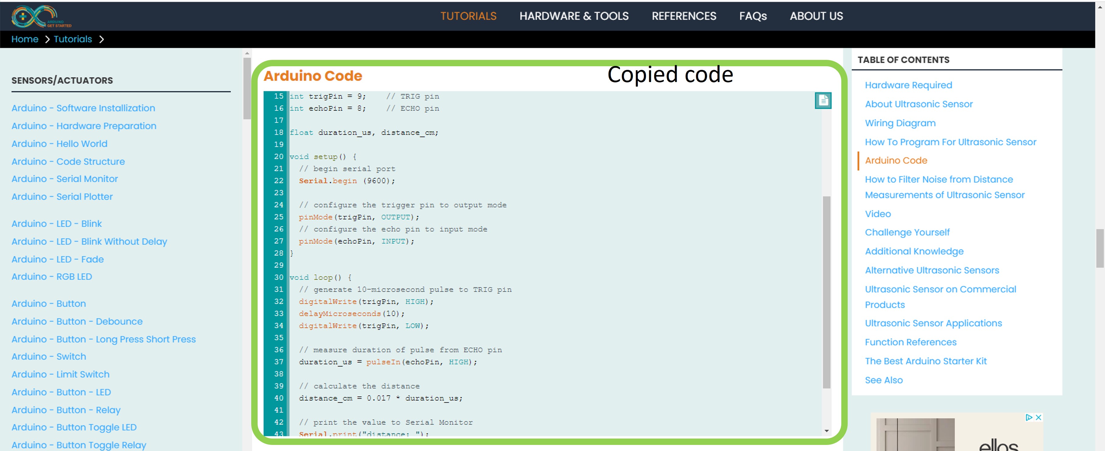
Step 2. I copied from Arduino site example code to edit.
Arduino.GetStarted.com / Arduino-Ultrasonic Sensor
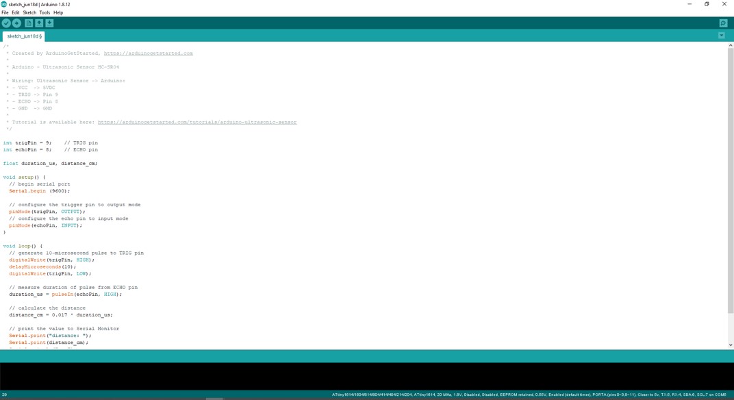
Step 3. I pasted example code to template.
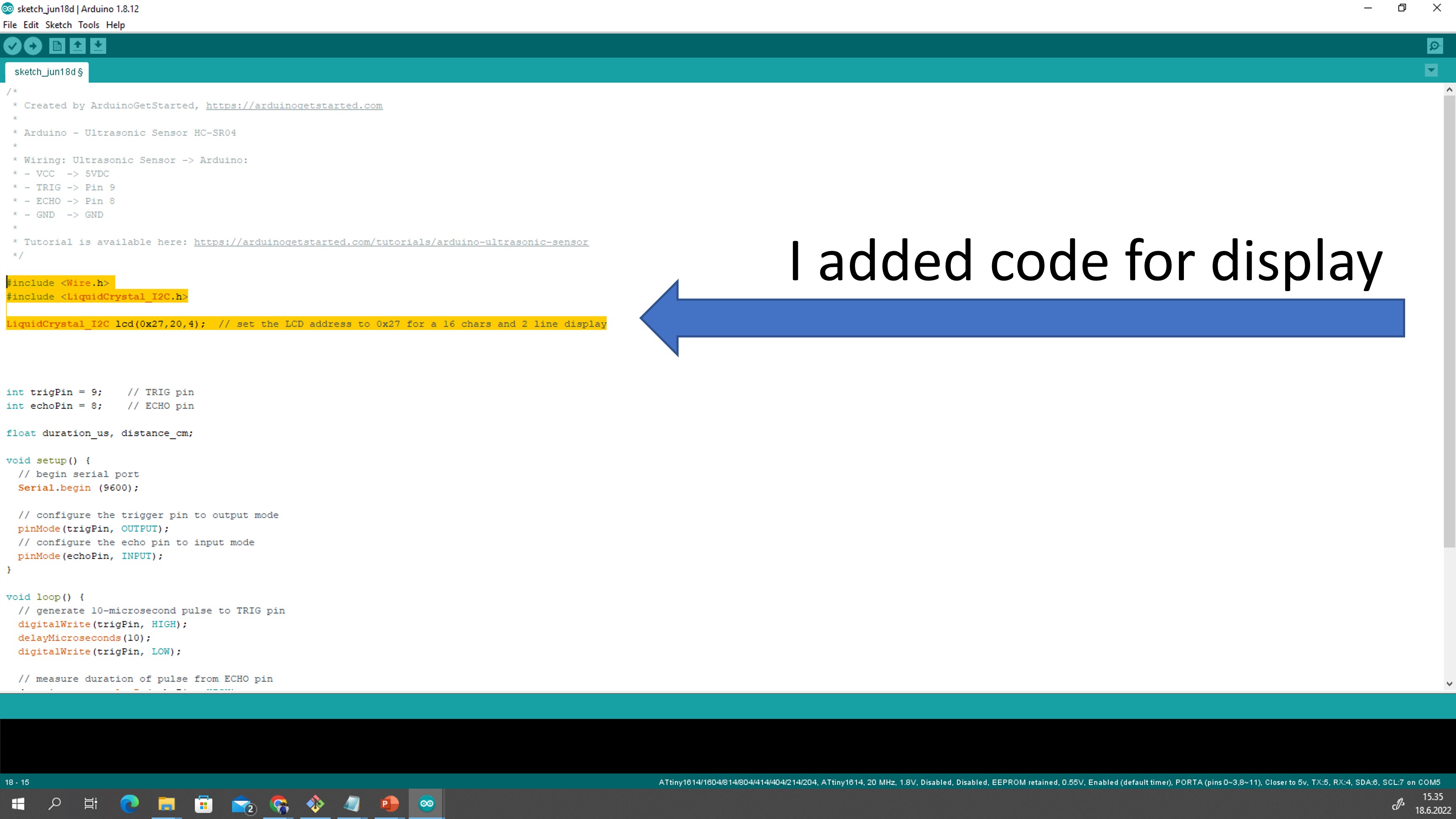
Step 4. I added code for display:
#include <Wire.h>
#include <LiquidCrystal_I2C.h>

LiquidCrystal_I2C lcd(0x27,20,4);  // set the LCD address to 0x27 for a 16 chars and 2 line display
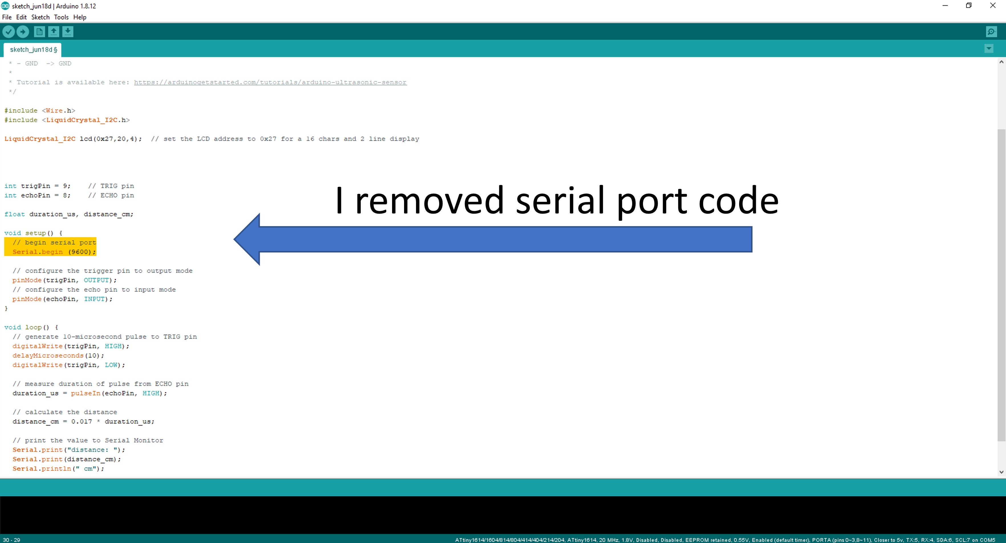
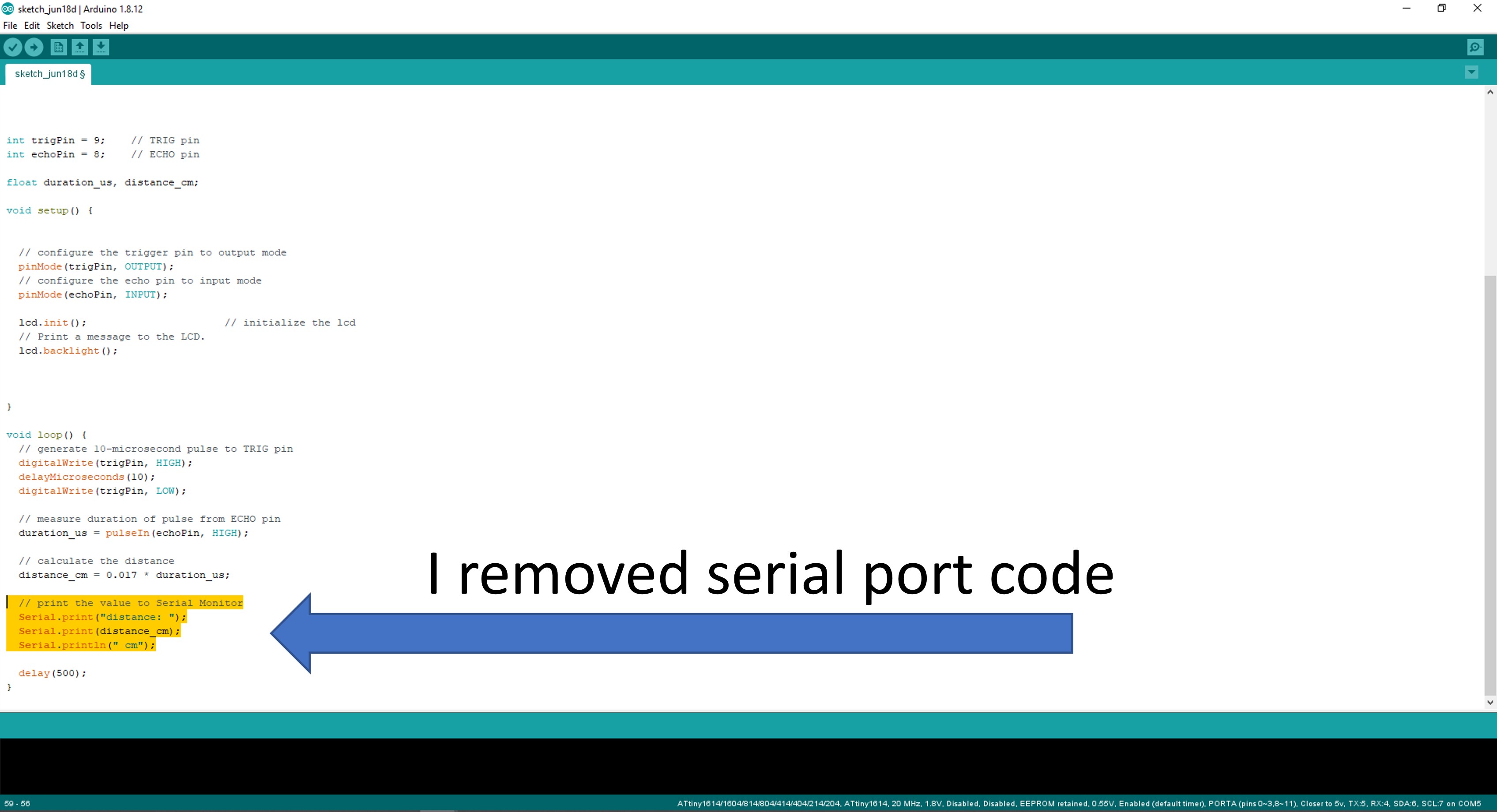
Step 5. I removed useless serial prot code
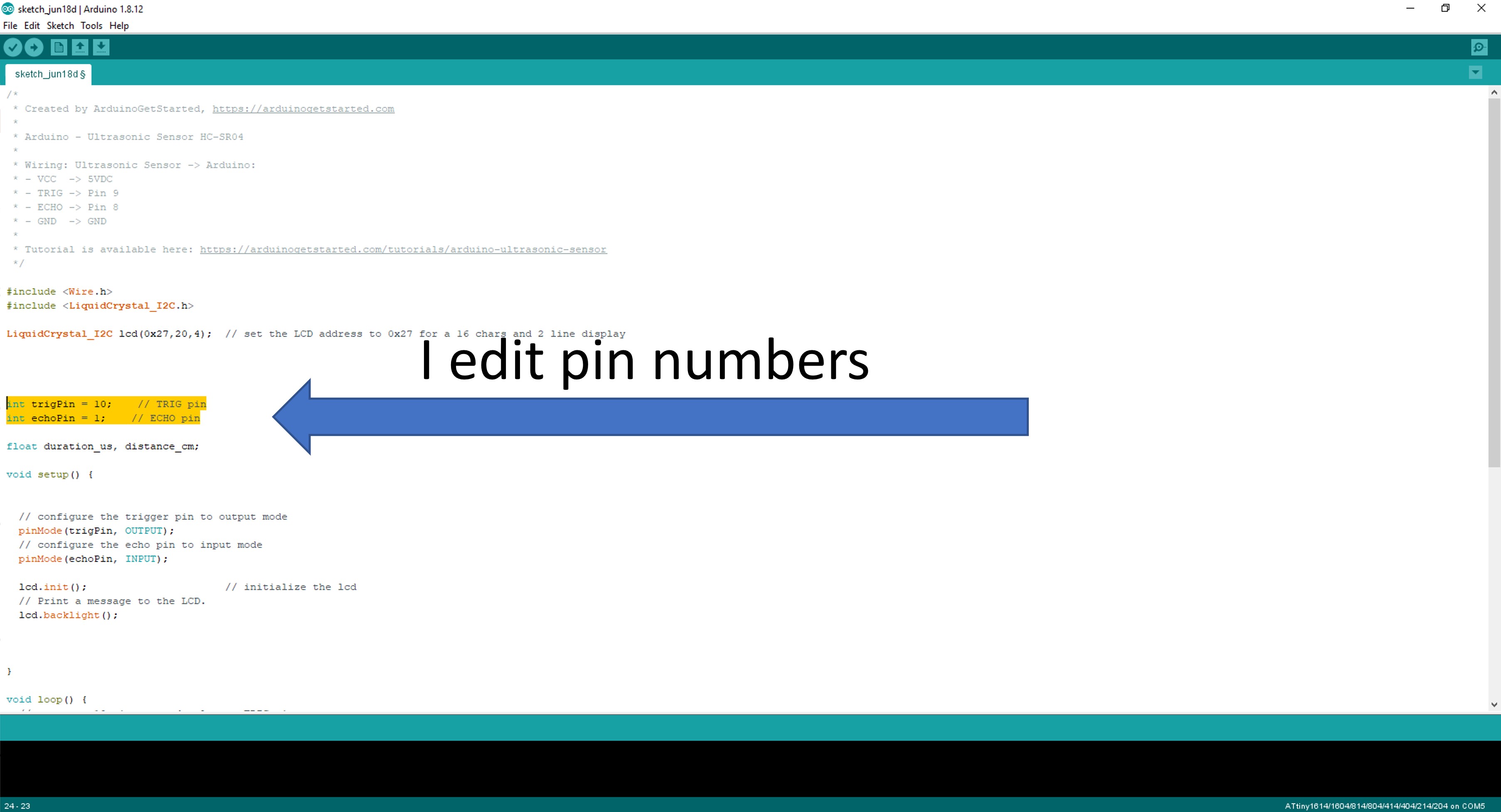
Step 6. I edited pin numbers
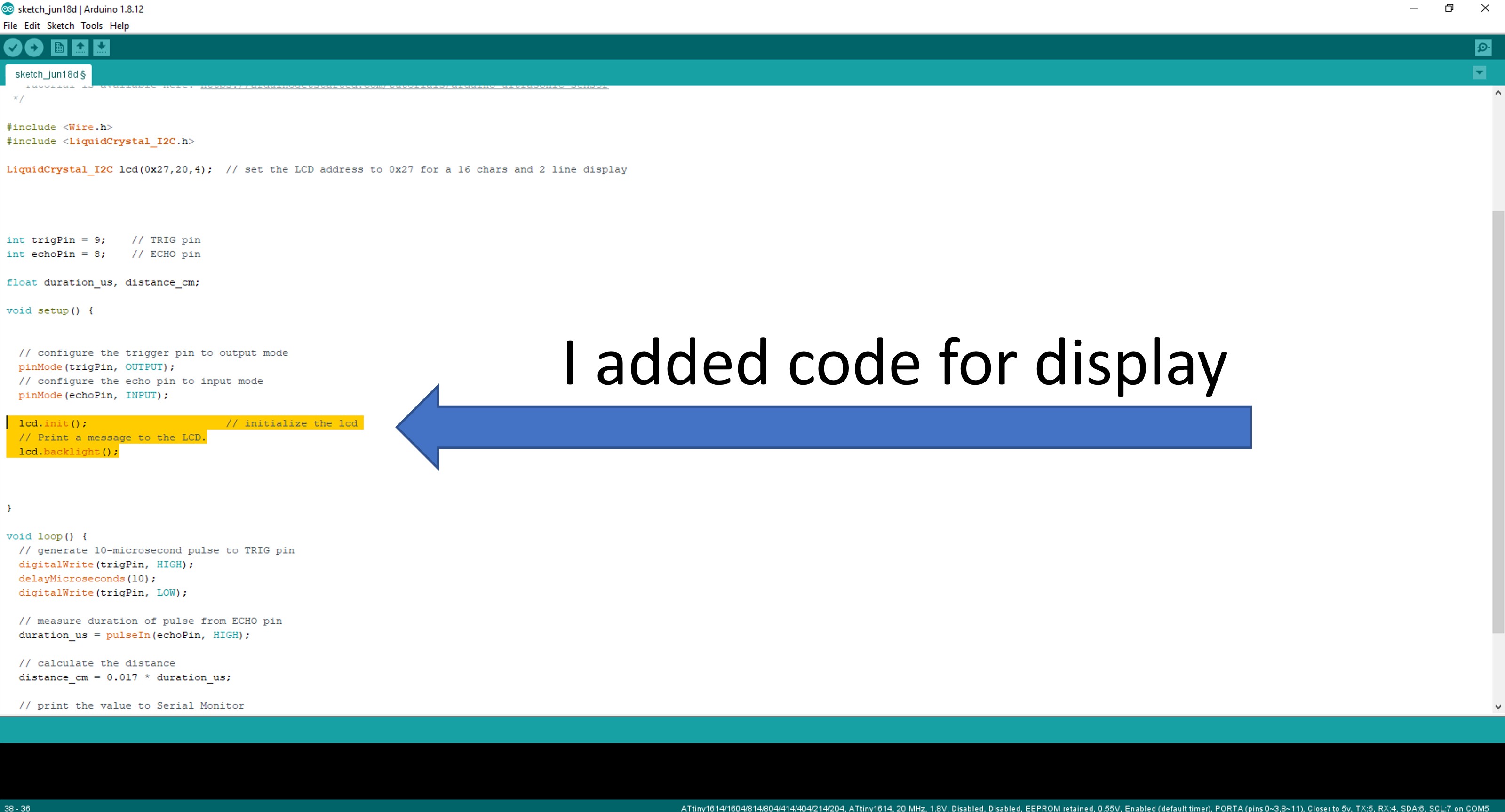
Step 7. I added code for display:
  lcd.init();                      // initialize the lcd
  // Print a message to the LCD.
  lcd.backlight();
Step 8. I removed useless serial port code
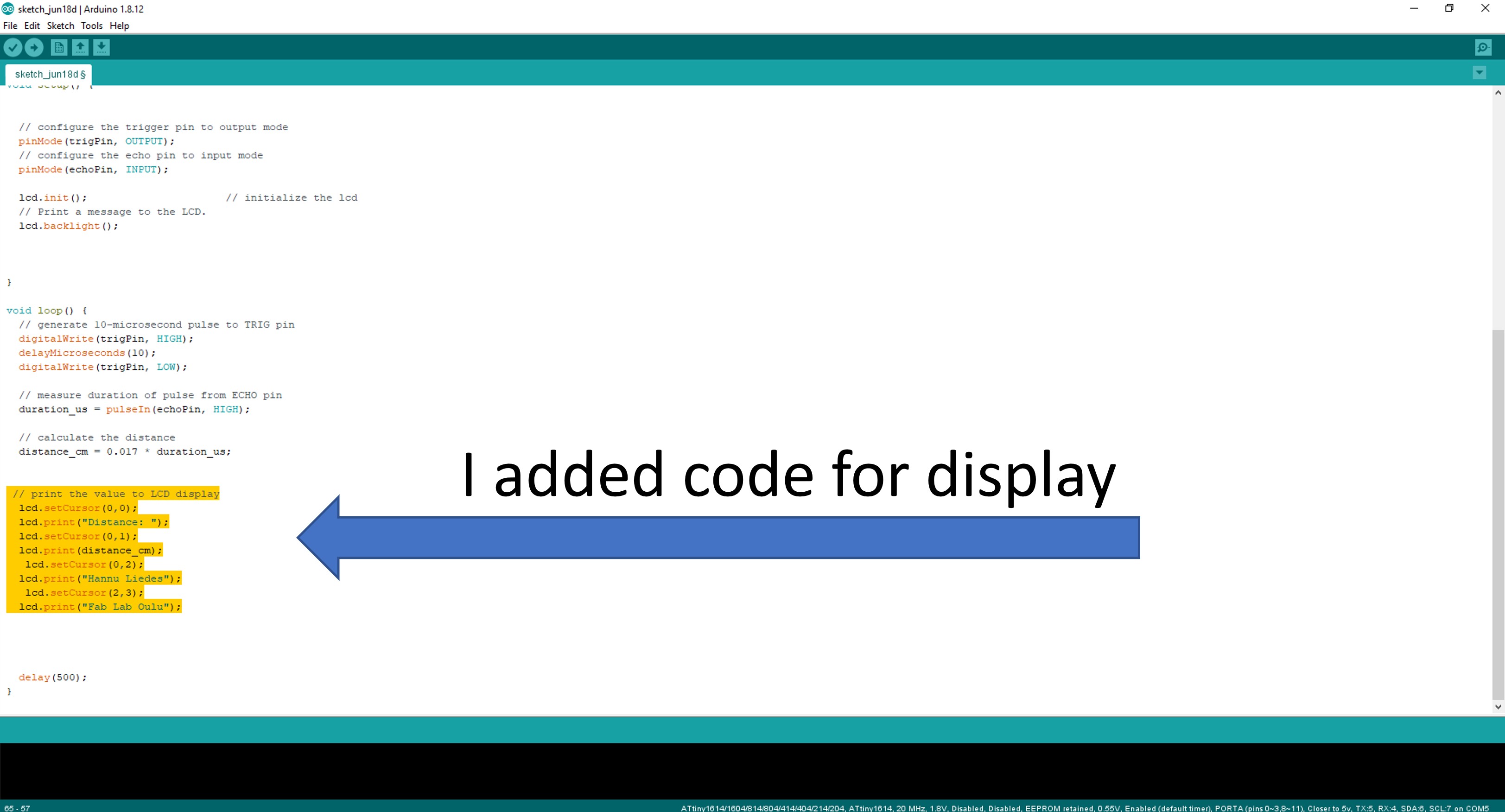
Step 9. I added code for display:
 // print distance to LCD display
  lcd.setCursor(0,0);
  lcd.print("Distance: ");
  lcd.setCursor(0,1);
  lcd.print(distance_cm);
   lcd.setCursor(0,2);
  lcd.print("Hannu Liedes");
   lcd.setCursor(2,3);
  lcd.print("Fab Lab Oulu");
Now my code is finish, but I have must add LiquidCrystal_I2C.h library
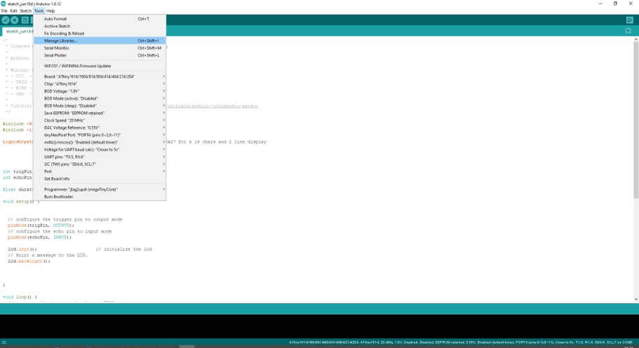
Step 10. I opened Tools / Manage Libraries…
Step 11. I
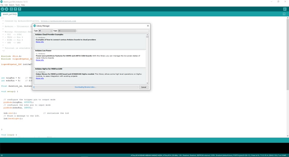
Step 12. I typed library name to field. Then I installed library.
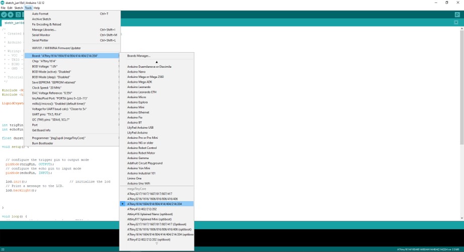
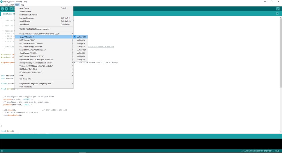
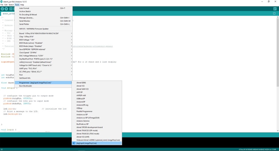
Step 13. Next I checked that microcotloller and programmer values were correct. Board: ATtiny 1614 .... Chip: ATtiny 1614 Programme: jtag2updi(medaTinyCore)
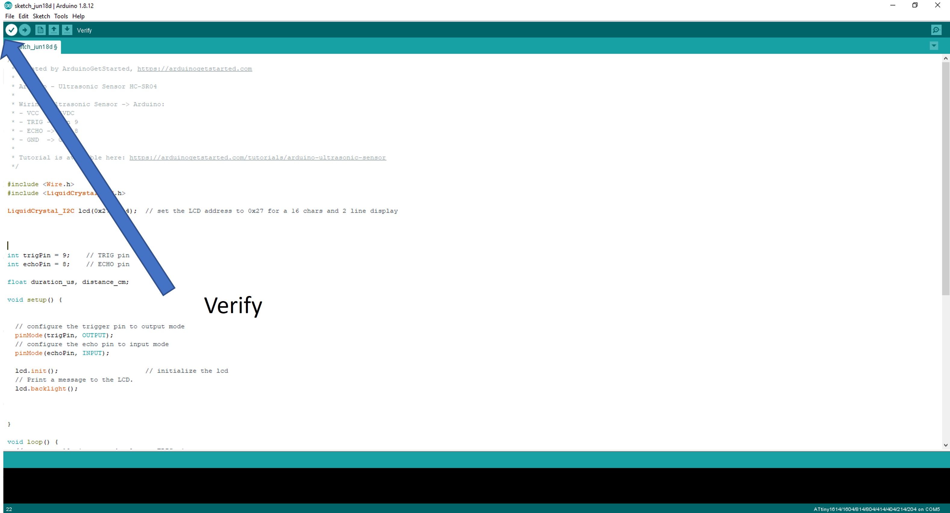
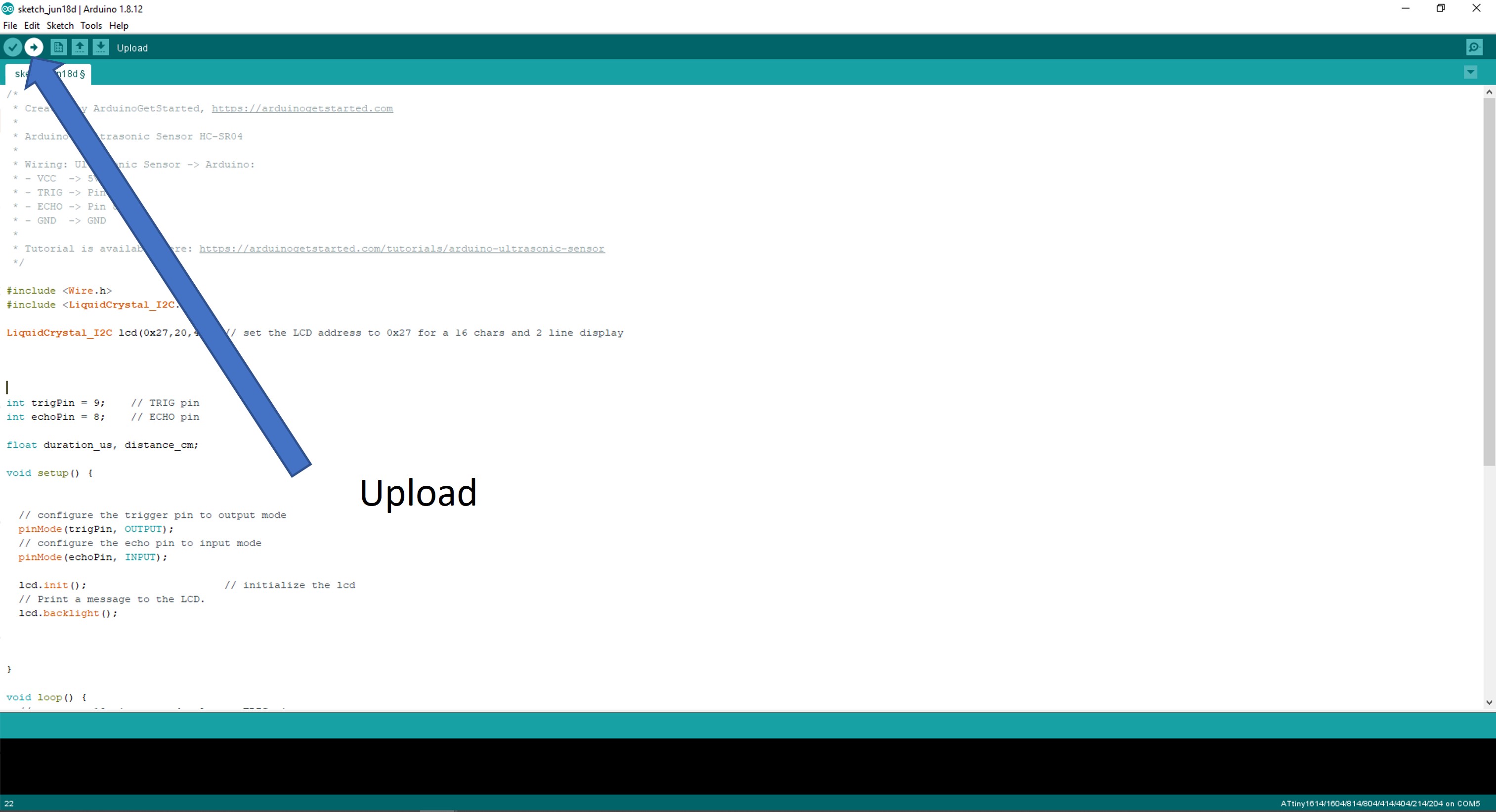
At last I veryfied code and then I uploaded code to board.
/*
 * Created by ArduinoGetStarted, https://arduinogetstarted.com
 *
 * Arduino - Ultrasonic Sensor HC-SR04
 *
 * Wiring: Ultrasonic Sensor -> Arduino:
 * - VCC  -> 5VDC
 * - TRIG -> Pin 9
 * - ECHO -> Pin 8
 * - GND  -> GND
 *
 * Tutorial is available here: https://arduinogetstarted.com/tutorials/arduino-ultrasonic-sensor
 * Hannu Liedes edit code 18.6.2022
 */

#include <Wire.h>
#include <LiquidCrystal_I2C.h>

LiquidCrystal_I2C lcd(0x27,20,4);  // set the LCD address to 0x27 for a 20 chars and 4 line display


int trigPin = 10;    // TRIG pin
int echoPin = 1;    // ECHO pin

float duration_us, distance_cm;

void setup() {

  // configure the trigger pin to output mode
  pinMode(trigPin, OUTPUT);
  // configure the echo pin to input mode
  pinMode(echoPin, INPUT);

    lcd.init();                      // initialize the lcd
      // Print a message to the LCD.
    lcd.backlight();


}

void loop() {
  // generate 10-microsecond pulse to TRIG pin
  digitalWrite(trigPin, HIGH);
  delayMicroseconds(100);
  digitalWrite(trigPin, LOW);

  // measure duration of pulse from ECHO pin
  duration_us = pulseIn(echoPin, HIGH);

  // calculate the distance
  distance_cm = 0.017 * duration_us;

 // print distance to LCD display
  lcd.setCursor(0,0);
  lcd.print("Distance: ");
  lcd.setCursor(0,1);
  lcd.print(distance_cm);
   lcd.setCursor(0,2);
  lcd.print("Hannu Liedes");
   lcd.setCursor(2,3);
  lcd.print("Fab Lab Oulu");


  delay(500);
}
Test is documented in 10. Input devices week
Group project
The members of the group:
- Achille Achille’s site
- Anssi Anssi’s site
- Jari Jari’s site
- Hannu
Our group compared the performance and development workflows for Arduino Uno and Atmel Nucleo STM32F401 microcontroller boards
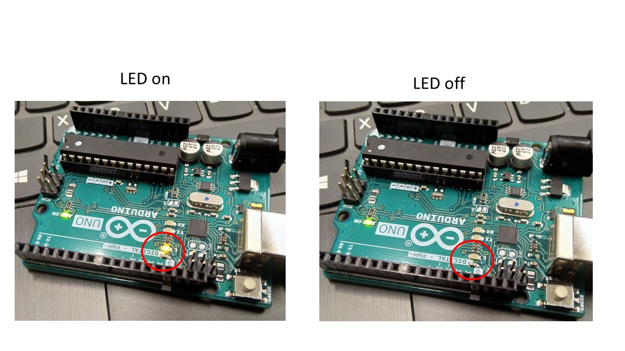
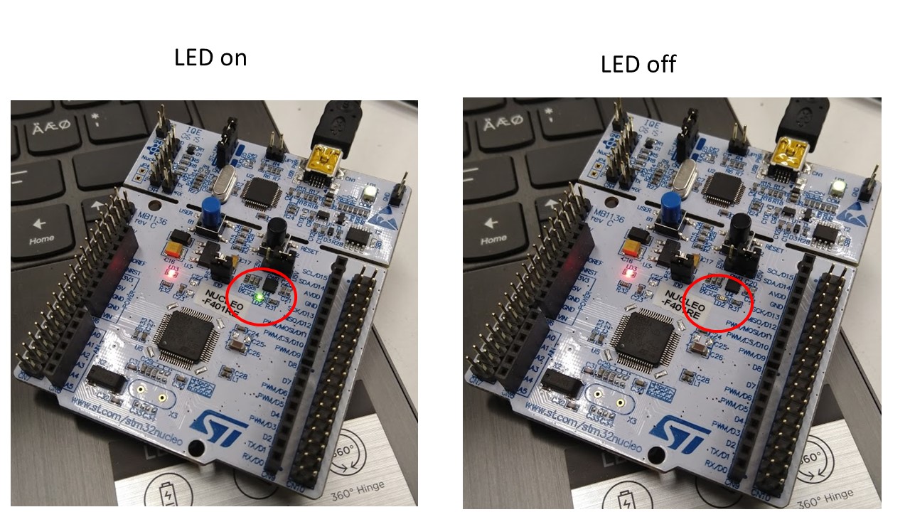
We tested development workflow to making an LED-blinking test. In test we blinked inside LED in microcontroller board. (5 seconds on, 5 seconds off, 5 seconds on .... )
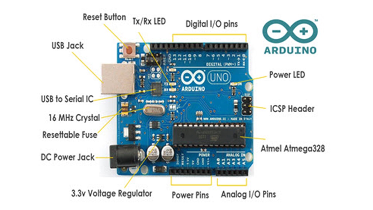
Arduino Uno
Arduino Uno base on the ATmega328P microconroller, which base on Harvard architecture 8-bit RISC processor core.
You can simulate small Arduino Uno projects in https://www.tinkercad.com/
An LED-blinking test in Arduino Uno
Step 1: First we connected Arduino Uno a standard USB cabel (Connector A to PC and connector B to Arduino Uno)
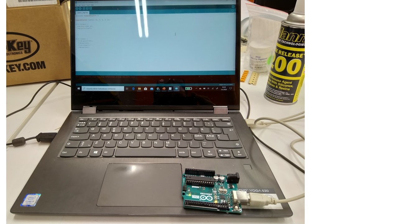
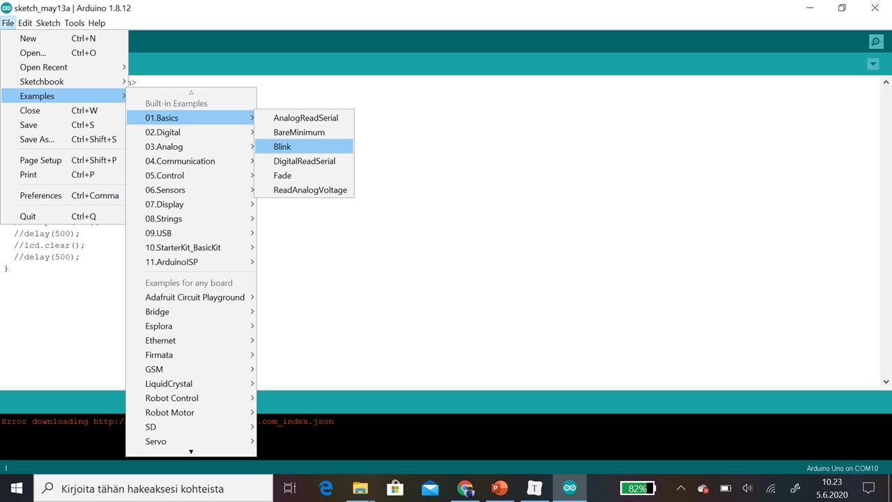
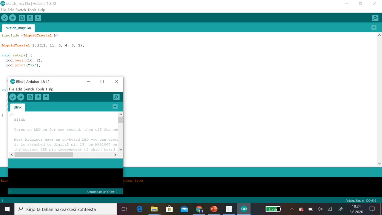
Step 2: Then we open Arduino Software (IDE). First we loaded Blink code:
1) File-Examples
2) 01.Basics
3) Blink
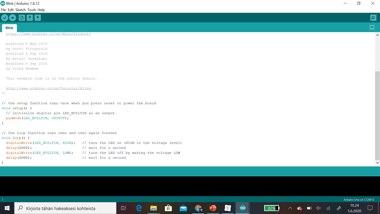
Step 2: Then loaded code opened in windows.
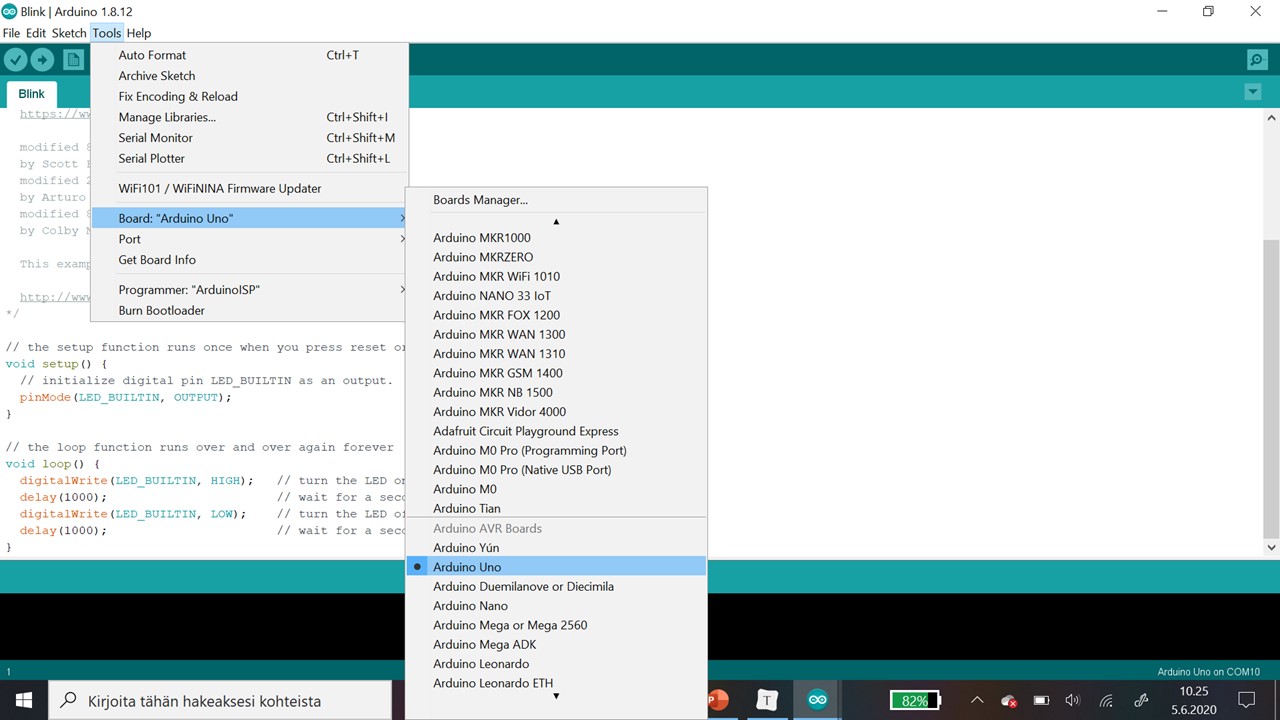
Step 3: Then we chose Arduino Uno board by picking Tools - Board - Arduino Uno.
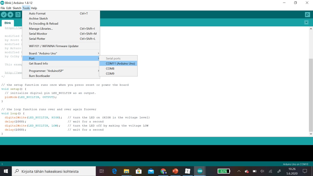
Step 4: Then we checked Port by Tools - Port.
Step 5: Then we uploaded code to Arduino Uno by pressing upload button (arrow to right)
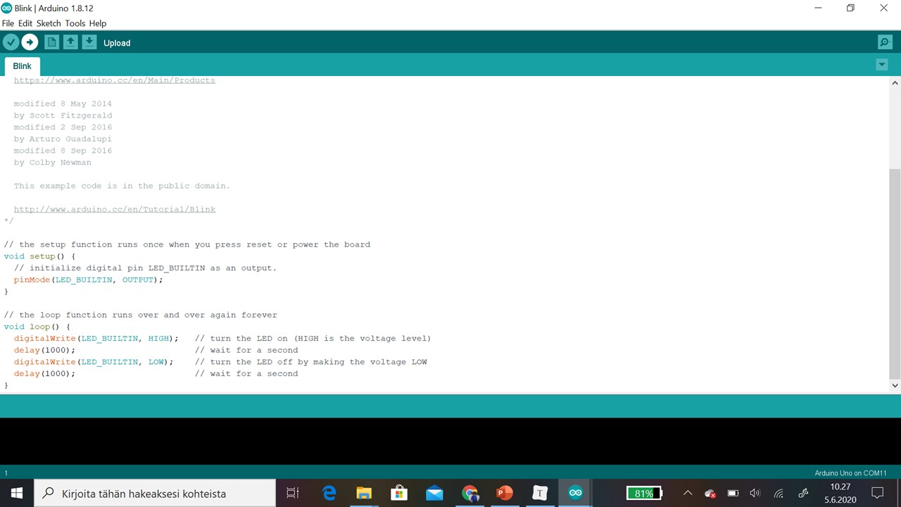
Step 6: On the while inside LED start to blink (5 seconds on, 5 seconds off .... )
/*
  Blink

  Turns an LED on for one second, then off for one second, repeatedly.

  Most Arduinos have an on-board LED you can control. On the UNO, MEGA and ZERO
  it is attached to digital pin 13, on MKR1000 on pin 6. LED_BUILTIN is set to
  the correct LED pin independent of which board is used.
  If you want to know what pin the on-board LED is connected to on your Arduino
  model, check the Technical Specs of your board at:
  https://www.arduino.cc/en/Main/Products

  modified 8 May 2014
  by Scott Fitzgerald
  modified 2 Sep 2016
  by Arturo Guadalupi
  modified 8 Sep 2016
  by Colby Newman

  This example code is in the public domain.

  http://www.arduino.cc/en/Tutorial/Blink
*/

// the setup function runs once when you press reset or power the board
void setup() {
  // initialize digital pin LED_BUILTIN as an output.
  pinMode(LED_BUILTIN, OUTPUT);
}

// the loop function runs over and over again forever
void loop() {
  digitalWrite(LED_BUILTIN, HIGH);   // turn the LED on (HIGH is the voltage level)
  delay(5000);                       // wait for 5 seconds
  digitalWrite(LED_BUILTIN, LOW);    // turn the LED off by making the voltage LOW
  delay(5000);                       // wait for 5 seconds
}
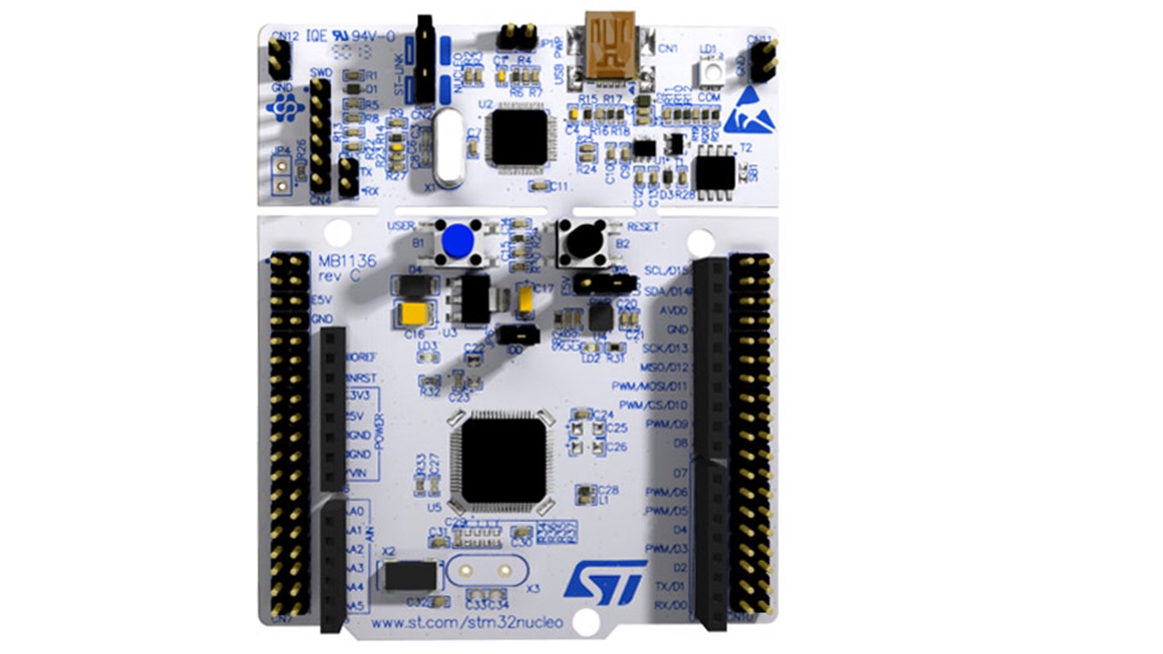
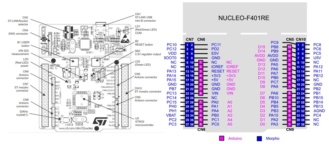
Atmel Nucleo STM32F401
ATMEL
Atmel Nucleo STM32F401
https://os.mbed.com/docs/mbed-os/v6.0/quick-start/build-with-the-online-compiler.html
http://ww1.microchip.com/downloads/en/DeviceDoc/Atmel-7810-Automotive-Microcontrollers-ATmega328P_Datasheet.pdf
An LED-blinking test in Atmel Nucleo STM32F401
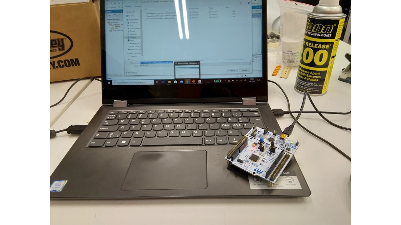
Step 1: First we connected Atmel Nucleo STM32F401 a standard USB cabel (Connector A to PC and connector mini B to Arduino Uno)
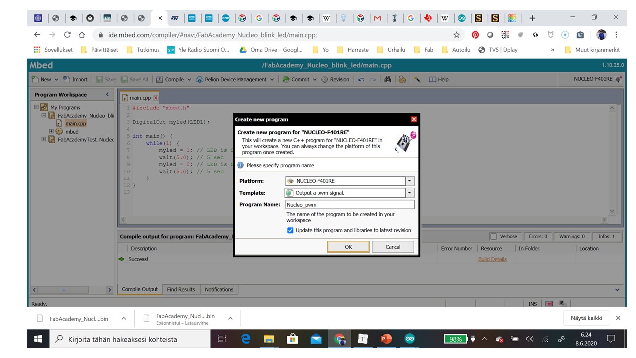
Step 2: First we chose Blink code by picking code from New… /New Program …
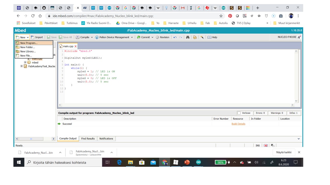
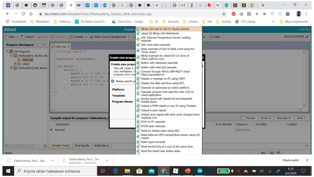
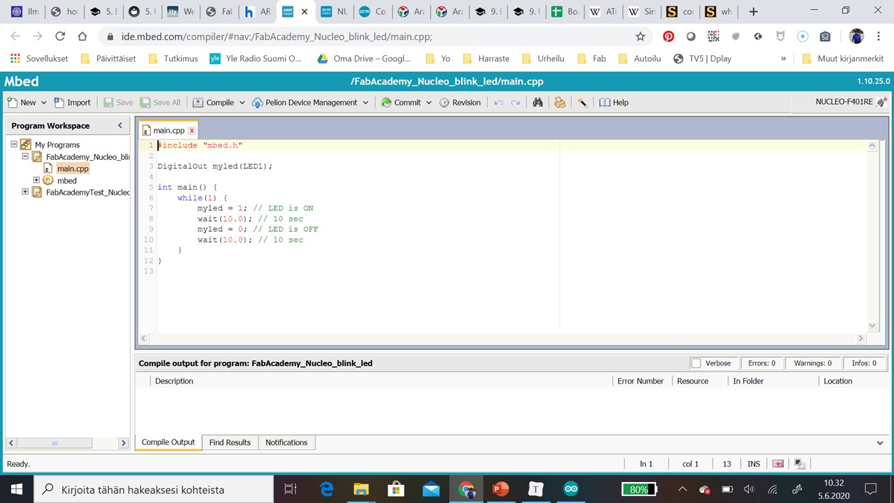
Step 3: Then we picked code from Template Blinky LED test for the ST Nucleo board
Step 4: Then we got template code
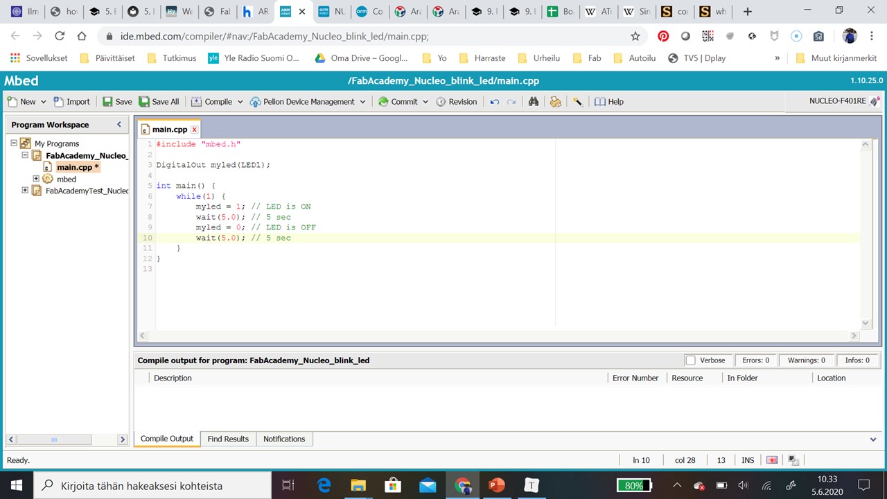
Step 4: Then we changed light on and light off times
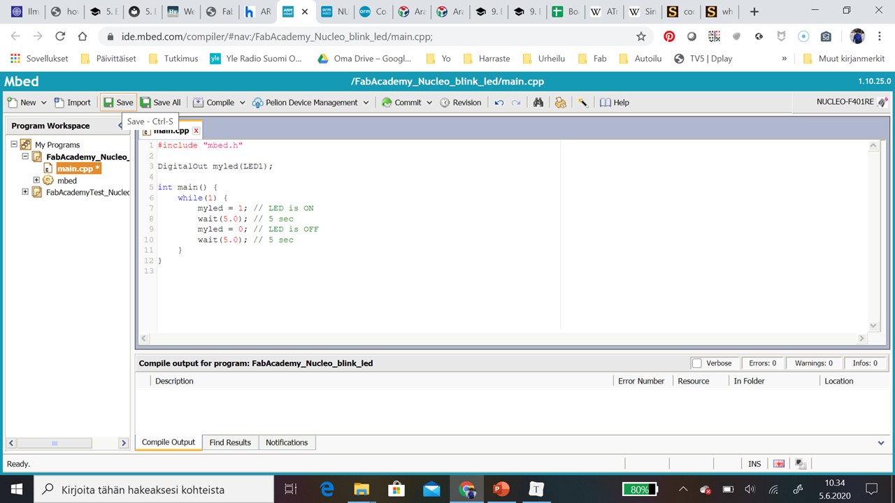
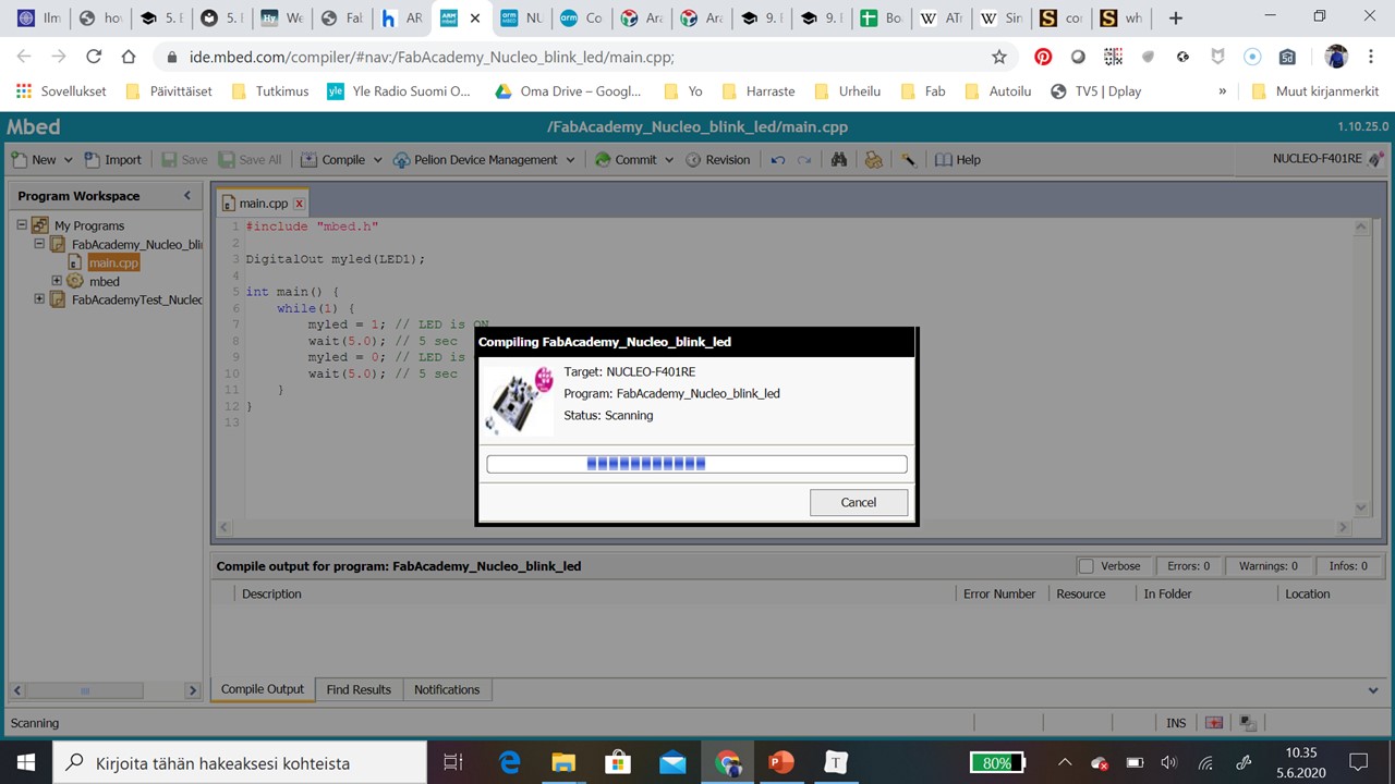
Step 5: Then we compiled code
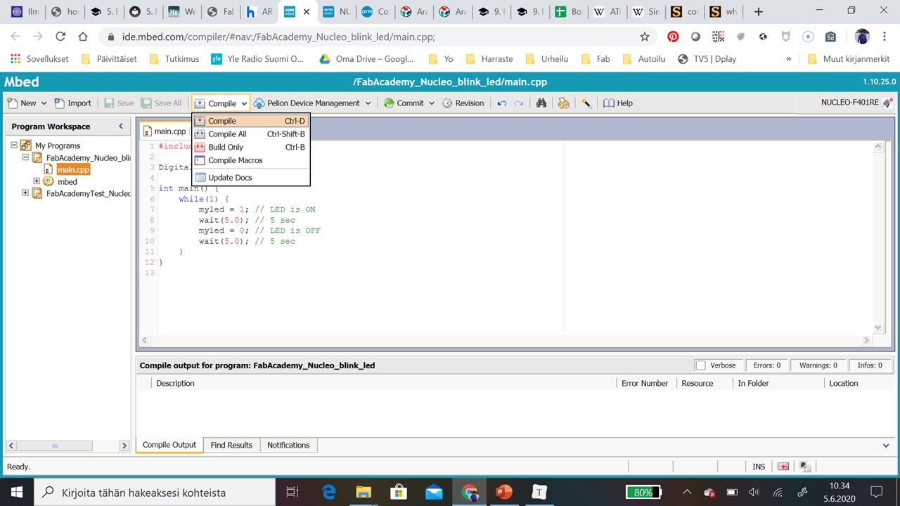
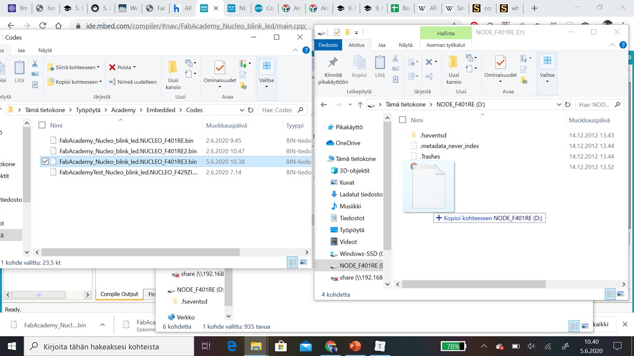
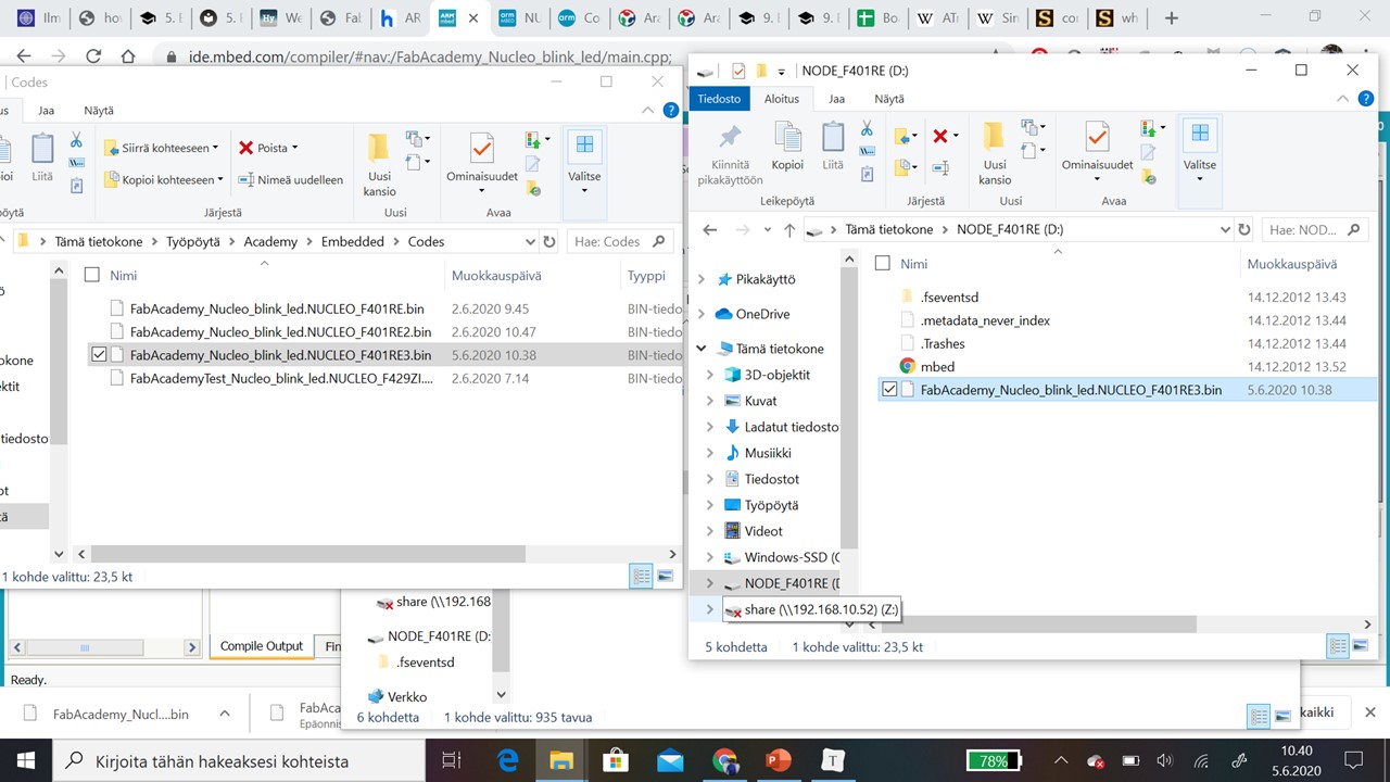
Step 6: Then we just copied compiled code to Node_F401RE.
Step 7: On the while LED started blinking.
#include "mbed.h"

DigitalOut myled(LED1);

int main() {
    while(1) {
        myled = 1; // LED is ON
        wait(5.0); // 5 sec
        myled = 0; // LED is OFF
        wait(5.0); // 5 sec
    }
}
Summary
| Arduino Uno | Atmel Nucleo STM32F401 | |
|---|---|---|
| Manufacturer | Atmel Corporation | Arm Holdings |
| Communication interface | *14 digital input/output pins (of which 6 can be used as PWM outputs), * 6 analog inputs, | * 4 pins for Digital Input/Output protocol 4 pins for PWM protocol * 3 pins for UART protocol * 3 pins for SPI protocol * 3 pins for I2C protocol 3 analog digital converter *2 analog inputs |
| Microcontroller | ATmega328P | |
| Processor | 8-bit RISC processor core | ARM®32-bit Cortex®-M4 CPU with FPU, RISC |
| Architecture | Harvard | Harvard |
| CPU Frequency | 84 MHz | |
| VDD (MCU) | 1.7V to 3.6V | |
| VIN (BOARD) | 6V to 20V | 7V to 15V |
| Flash Memory | 32Kb (bootloader use 0.5Kb) | 512Kb |
| SRAM | 2 kb (ATmega328) | 96Kb |
Useful links
https://www.espruino.com/ReferenceNUCLEOF401RE
https://microcontrollerslab.com/stm32-nucleo-board-pinout-features-applications-programming-peripherals/
Hero Video
This video is hero video for weeks: Embedded programming, Output device and Input device