15. Networking and communications
Reguirements
individual assignment:
  design, build, and connect wired or wireless node(s)
  with network or bus addresses
group assignment:
send a message between two projects
individual project
This week individual assignment: design, build, and connect wired or wireless node(s) with network or bus addresses
Research
The main idea of serial communication is that one device is master device and rest of devices are sub devices. Every Sub device have to have own individual address. In this case addresses are node numbers.
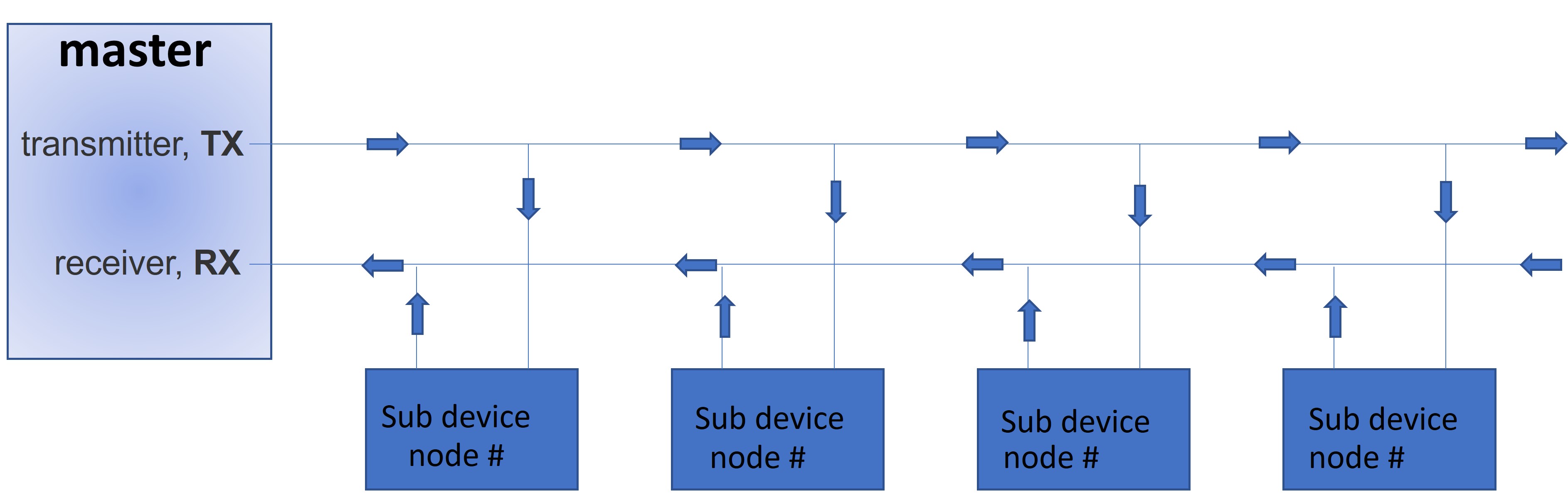
When master device send message. Every sub sevices got that same message and read it, but only that board reacts where incomingByte match node number of board. In if-statement block of code to be executed if the condition is true.
    incomingByte = mySerial.read();
if (incomingByte == node) {

// block of code


}
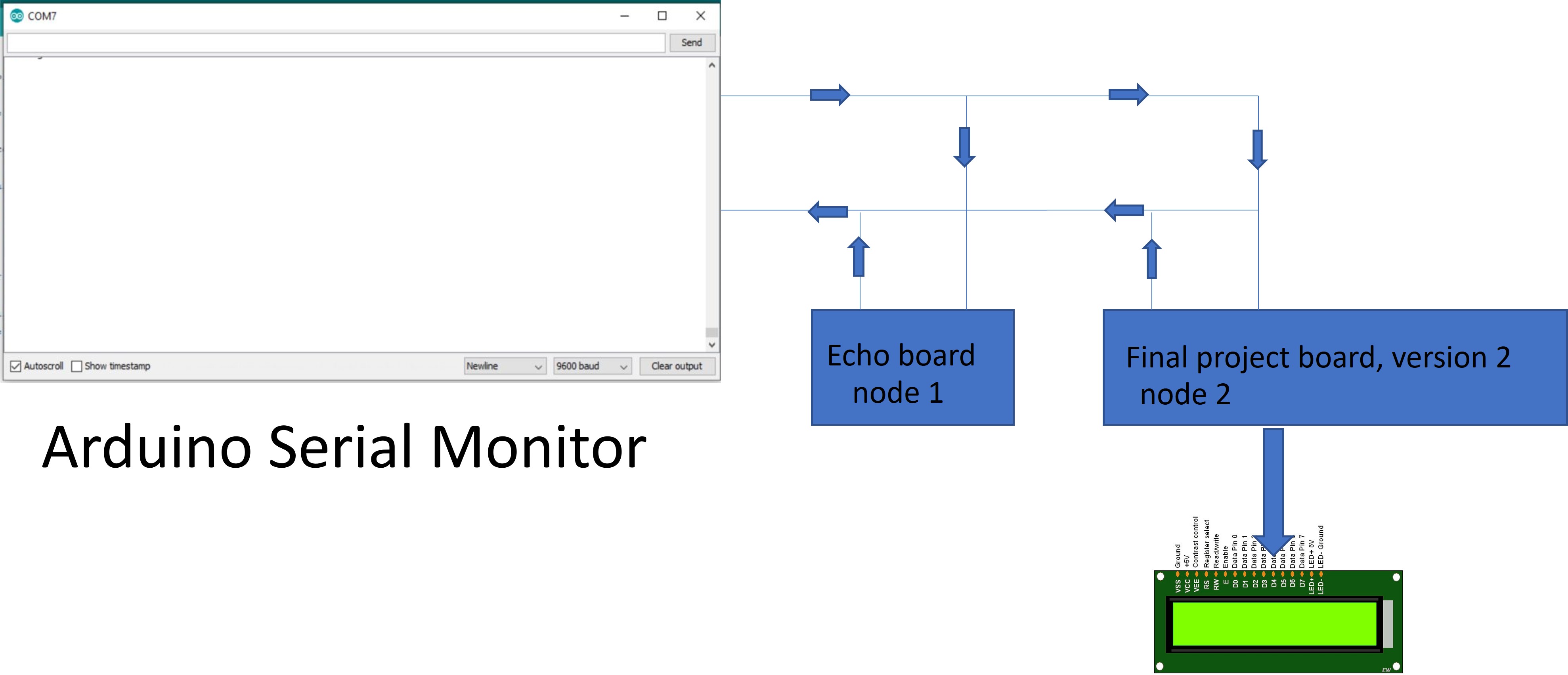
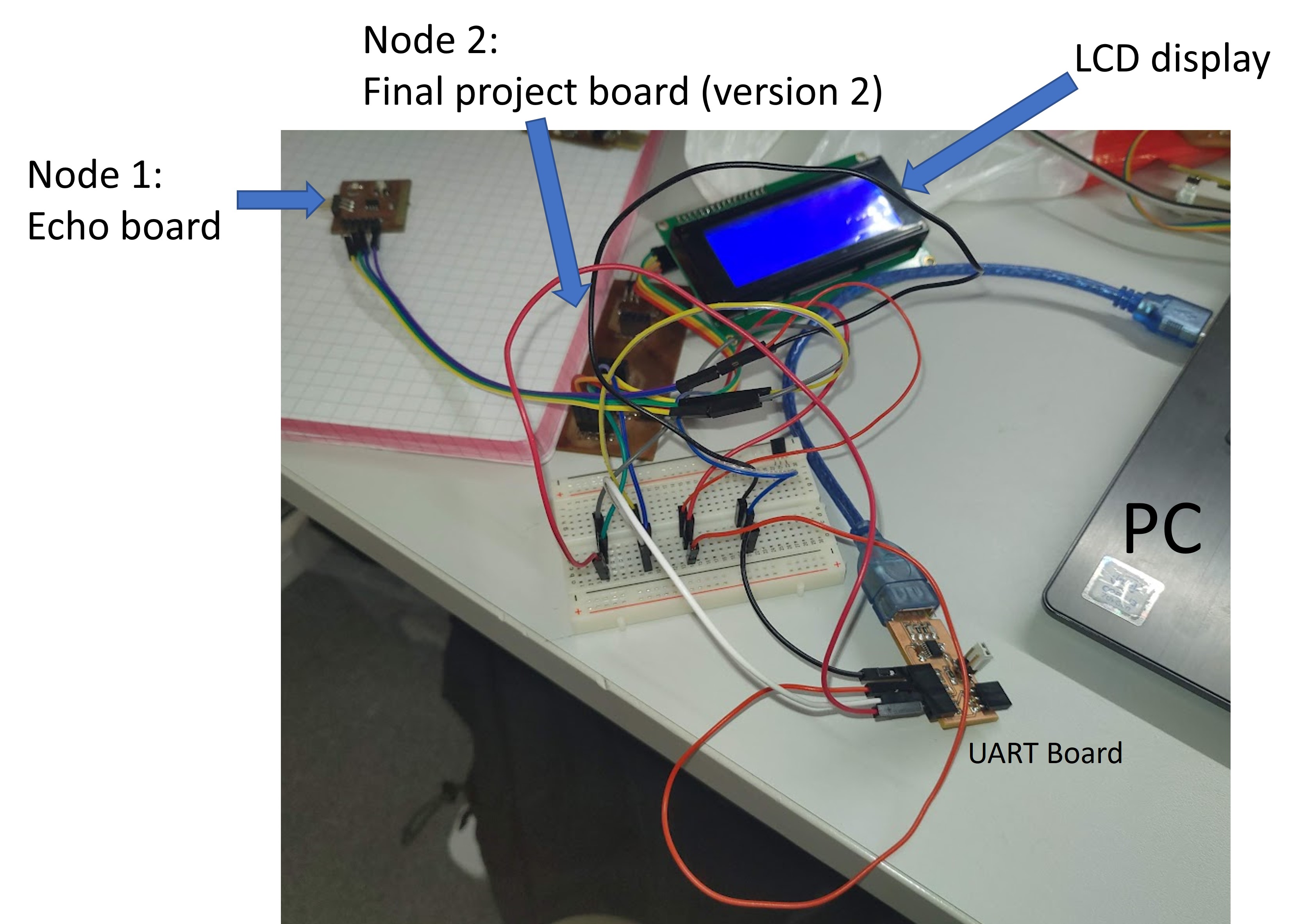
My test system consist of two devices systems:
- Node 1: Echo board. LED blinking
- Node 2: Final project board, version 2. Message on LCD display.
Architechture of network
On Actual network, I made connections with jumper wires on breadboard.
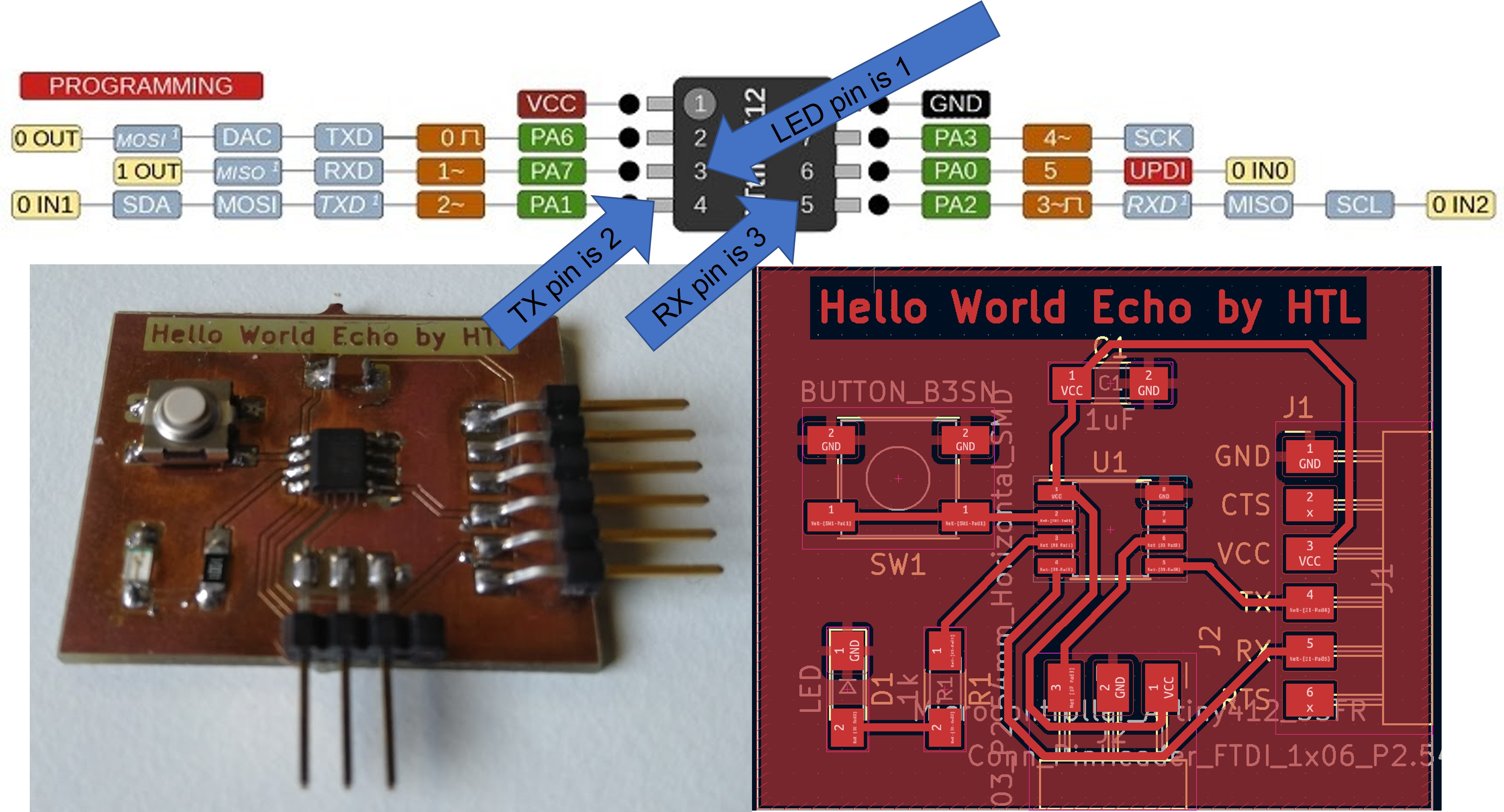
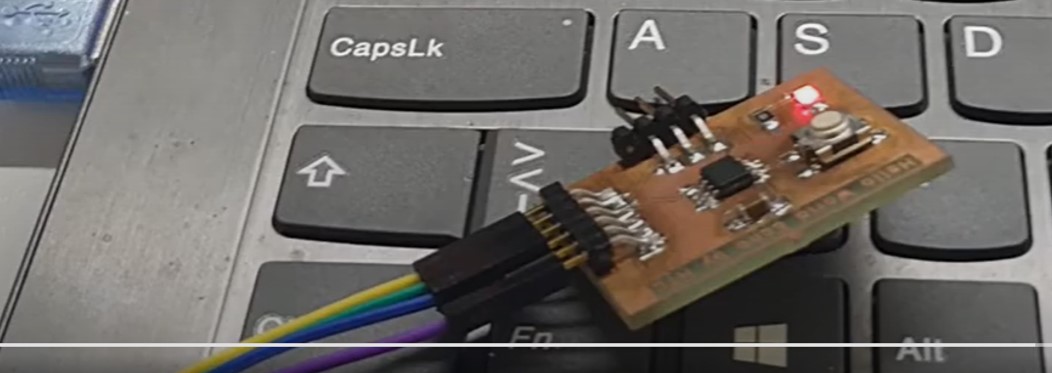
Node 1: Echo board.
On node 1 board blinked LED when message ‘1’ was sended on Arduino Serial Monitor
I copied example code from Noora Nyberg’s page. I checked and edited code:
SoftwareSerial mySerial(3, 2); // RX, TX (ATTiny DIGITAL/ANALOG pin number)

const char node = '1'; // network address
const int ledPin = 1; // the number of the LED pin
Node 1 code (Tested)
#include <SoftwareSerial.h>
SoftwareSerial mySerial(3, 2); // RX, TX (ATTiny DIGITAL/ANALOG pin number)

const char node = '1'; // network address
const int ledPin = 1; // the number of the LED pin
int incomingByte;

void setup() {
  mySerial.begin(9600);
  pinMode(ledPin, OUTPUT);
  pinMode(3, INPUT);
}

void loop() {
  if (mySerial.available() > 0) {
    digitalWrite(ledPin, HIGH);
    delay(200);
    digitalWrite(ledPin, LOW);
    delay(200);
    incomingByte = mySerial.read();
    if (incomingByte == node) {
      digitalWrite(ledPin, HIGH);
      pinMode(3, OUTPUT); // open line to write
      mySerial.print("node ");
      mySerial.println(node);
      pinMode(3, INPUT);
      delay(1000);
      digitalWrite(ledPin, LOW);
    }
  }
}
Node 1 board reaction when number 1 was typed on Serial Monitor
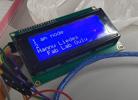
Node 2: Final project board, version 2.
I connected LCD display to board such as I have documented on Output devices week.
I used same code such as Node 1. I checked and edited code:
SoftwareSerial mySerial(4, 5); // RX, TX (ATTiny DIGITAL/ANALOG pin number)
I added code for LCD display
#include <Wire.h>
#include <LiquidCrystal_I2C.h>

LiquidCrystal_I2C lcd(0x27,20,4);  // set the LCD address to 0x27 for a 20 chars and 4 line display
and to void setup()-statement
 lcd.init();                      // initialize the lcd
      // Print a message to the LCD.
 lcd.backlight();
Node 2 code (Tested)
#include <SoftwareSerial.h>
SoftwareSerial mySerial(4, 5); // RX, TX (ATTiny DIGITAL/ANALOG pin number)

#include <Wire.h>
#include <LiquidCrystal_I2C.h>

LiquidCrystal_I2C lcd(0x27,20,4);  // set the LCD address to 0x27 for a 20 chars and 4 line display


const char node = '2'; // network address
const int ledPin = 1; // the number of the LED pin
int incomingByte;

void setup() {
  mySerial.begin(9600);
  pinMode(ledPin, OUTPUT);
  pinMode(3, INPUT);

 lcd.init();                      // initialize the lcd
      // Print a message to the LCD.
 lcd.backlight();


}

void loop() {
  if (mySerial.available() > 0) {
    digitalWrite(ledPin, HIGH);
    delay(200);
    digitalWrite(ledPin, LOW);
    delay(200);
    incomingByte = mySerial.read();
    if (incomingByte == node) {
      //digitalWrite(ledPin, HIGH);
      //pinMode(3, OUTPUT); // open line to write
      mySerial.print("node ");
      mySerial.println(node);
      //pinMode(3, INPUT);
      //delay(1000);
      //digitalWrite(ledPin, LOW);

      // print distance to LCD display
        lcd.setCursor(0,0);
        lcd.print("I am node ");
        lcd.setCursor(0,1);
        lcd.print(node);
         lcd.setCursor(0,2);
        lcd.print("Hannu Liedes");
         lcd.setCursor(2,3);
        lcd.print("Fab Lab Oulu");
        delay(2000);
        lcd.clear();

    }
  }
}
Node 2 board reaction when number 2 was typed on Serial Monitor
Conclusion
- First, breadboard is little bit Unstable platform. One wire was unfastened on while.
- MIT App Inventor was very interesting app. “I’ll be back”
- Note: It coud be possible send tex using html site on your PC.