Week14 Networking and Communications
I2C communication on ATtiny85
First, upload ArduinoISP code to Arduino UNO
Then I connected ATtiny85 with Arduino and upload the I2C-slave code to ATtiny85.
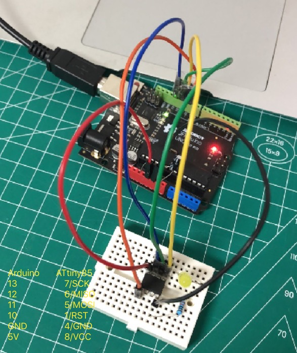
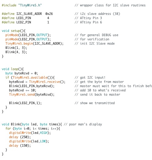
Add the TinyWireS library and upload the example code.
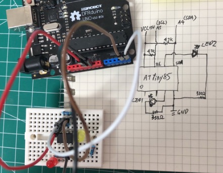
The circuit is as below:
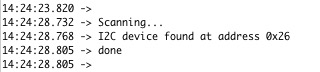
Use the I2CScan code in week11’s assignment to check the I2C address, it was 0x26 as expected.
Then wrote the ArduinoI2C code and upload to Arduino.
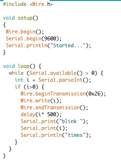
Tested and it worked fine. Use Serial Monitor to send 3 to Arduino, Arduino read and forward the number to ATtiny85. The LED1 blinked 3 times, then LED2 blink once. Then send 5 and LED1 blinked 5 times and LED2 blinked once.
Then I write code to let ATtiny85 send data and Arduino read data:
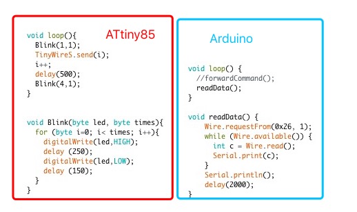
It worked, but sometime there is no output, although the LED kept blinking. I’ve no idea about this problem yet.

P.S. before this success run, I had followed the tutorial. To my surprise, the bytes read from ATtiny85 is always 255. Not quite sure about the reason either. Maybe there was somthing wrong in the library.

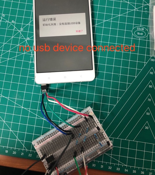
Android communicate with Arduino via USB-OTG cable
On Week12, I failed to make Android talk with Arduino. Then I realized that OTG is slightly different from normal usb cable, that the ID pin need to connect with ground.
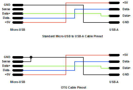
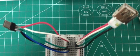
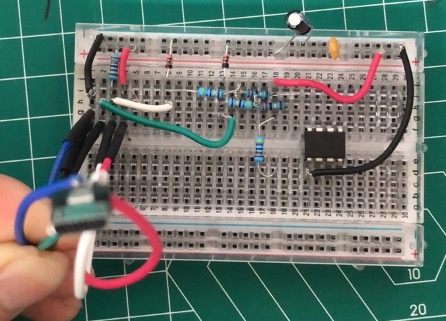
I make some usb headers and use bread-board to connect a mini-male with typeA-female. The ID pin (blue) is connect with ground pin. That makes a USB-OTG cable.
I tried with my Huawei Honor, but still failed. I did a search, and sadly to find Honor did not support OTG, and it could not be rooted.
Then I found my old android phone, and it can talk with Arduino now. Android played as the USB host.
Then I tried with Arduino’s other pins, rather than use the USB port directly. And they could not talk then. Then I realized that there was more to do on the USB device side.
I read the articles in V-USB and also another different approach, create circuits accrodingly, but they all failed. One possible reason is I didn’t use the right diode. Actually I’m still quite understand zener diode, and I need to learn more about it.
The first approach
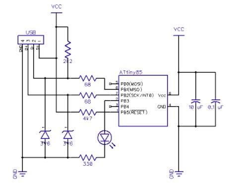
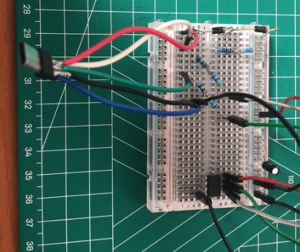
The second approach
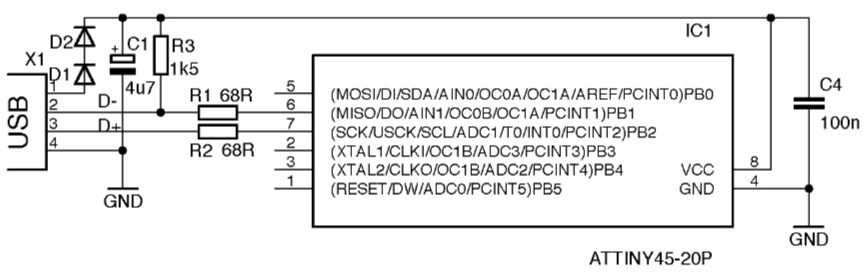
Although for the second approach, I checked the voltage and it was 3.6v as required. So I think another reason was on the software side. I didn’t quite understand the v-usb code either. Also need to learn this.
For final project: detect if smart phone is removed from the lamp.
At first I wanted to use the USB port to detect if phone is connected or not, and also use phone to play music. I even searched and learned approach to do OTG and charging simultaneously.
However, as my daily used Honor phone did not support OTG and cannot be rooted, I had to gave up this idea.
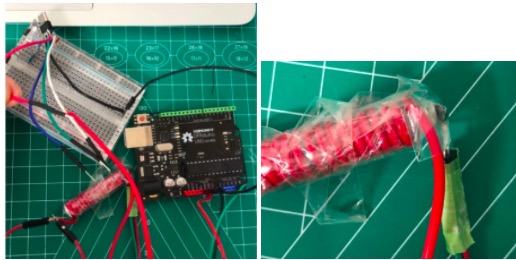
Then I decided to use current detection.
I wrapped the wire around a iron nail, and use tape to attach a A324 hall sensor with it.
Use the analogRead code:
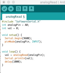
And can find the output changed slightly when plug on/off (off–509, on–502).
Seems it can work, but still have two problems:
1. it’s not sensitive enough. I will buy a high accurate current sensor instead.
2. What if the phone is full of charge? Will their be no current then? I need to do further experiment.