Week09. Input Devices
1. Understand analog value
1.1 Use micro:bit to check the photoresistor
I have a micro:bit kit with lots of sensors, which I bought several years ago. So first of all, I need to make sure the they work fine. I use micro:bit to check the photoresistor.
GND–GND
VCC–5V VCC
AO – P1
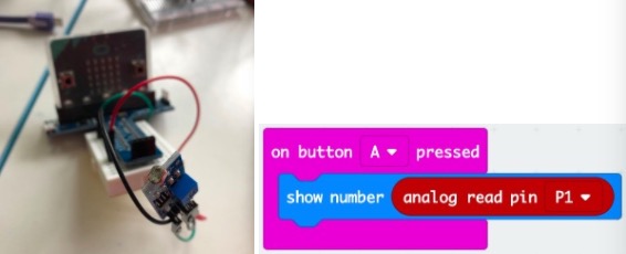
Move the light sensor to different places, and press buttonA on microbit. The output is:
vary dark: ~900
dark: ~500
little light: ~100
very strong light: ~20
1.2 Use Arduino UNO to learn the C programming library for analog input
What does the analog value mean? I found answer from the analogRead() function reference.
Arduino boards contain a multichannel, 10-bit analog to digital converter. This means that it will map input voltages between 0 and the operating voltage(5V or 3.3V) into integer values between 0 and 1023. On an Arduino UNO, for example, this yields a resolution between readings of: 5 volts / 1024 units or, 0.0049 volts (4.9 mV) per unit. See the table below for the usable pins, operating voltage and maximum resolution for some Arduino boards.
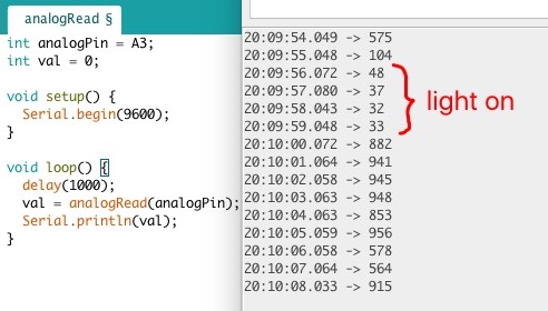
Uno has 6 analog input pins (A0~A5). I connect photoresistor’s AO pin to Arduino’s Pin3. Use analogRead() to get the value.
1.3 Try ATtiny85 with analog input feature
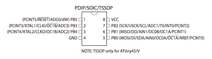
From the datasheet, we can know that pb2, pb3, pb4 can be used as analog input.
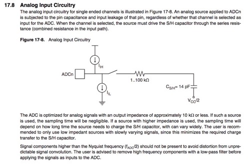
The datasheet also explains how analog input works.
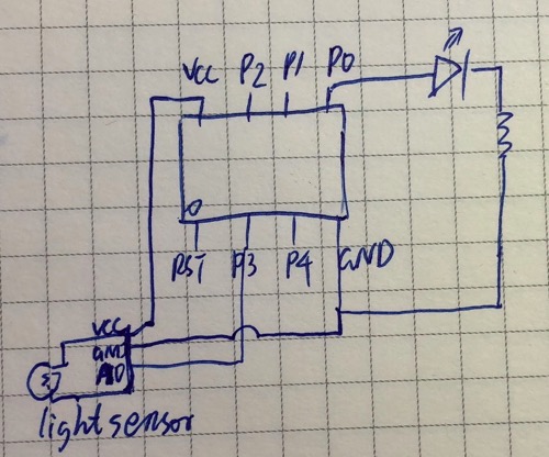
I connect photoresistor, LED and a resistor with ATtiny85 as below:
And the code as below:
The result:
1.4 What if I use non-analog input pin?
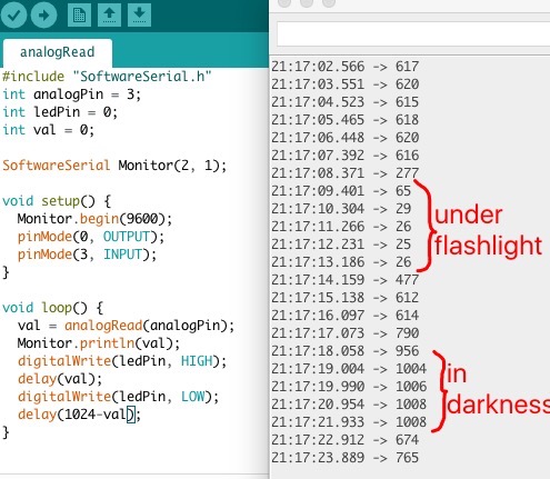
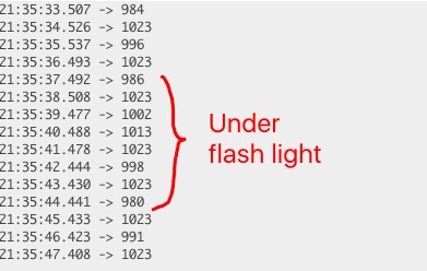
I switch P0 and P3, connect photoresistor to P0 and LED to P3, and got very weak light.
Serial monitor indicated that even when it is under flash light, the value is still around 1000 (the digital HIGH).
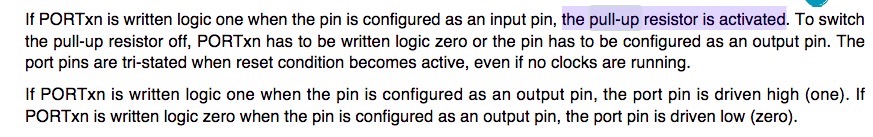
Why? We can find the answer from datasheet.
2. Compare different light sensors
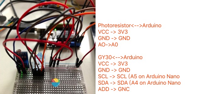
2.1 the experiment with photoresistor and GY30(BH1750)
I connect both photoresistor and a GY30 light sensor to arduino.
The connection:
I followed the BH1750 github repro to use GY30.
The code (need to download and include the BH1750 zip file from github repo:
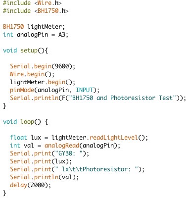
The result:
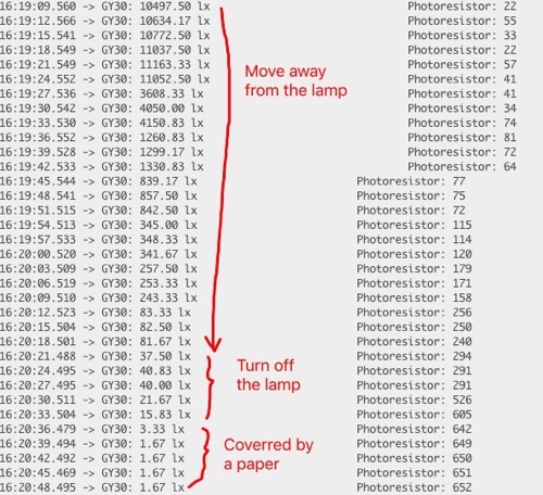
From the result, we can find the GY30 sensor has a more wide range of vlues, and is more stable.
2.2 Understand GY30(BH1750)
What are SCL and SDA pins? The most important component in GY30 is BH1750. I found the answer from BH1750 datasheet.
The BH1750 has a Logic + I²C interface:
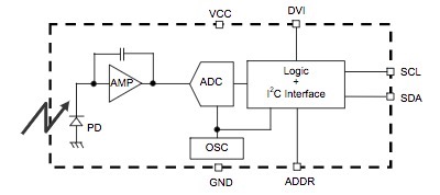
The I²C (Inter-Integrated Circuit) uses two bidirectional open collector or open drain lines, Serial Data Line (SDA) and Serial Clock Line (SCL).
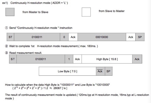
How to read the light level by SDA and SCL?
The sample in datasheet indicates how BH1750 works with master (here is Arduino)
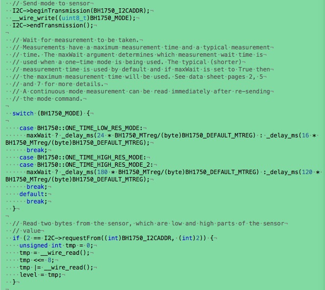
Go through the code in BH1750.cpp (https://github.com/claws/BH1750/blob/master/BH1750.cpp) with the datasheet helped a lot.
3. Compare different tempreature sensors
3.1 The Thermistor
Use the same connection and code as the photoresistor
What does these value mean? Need to calculate according to resistor values.
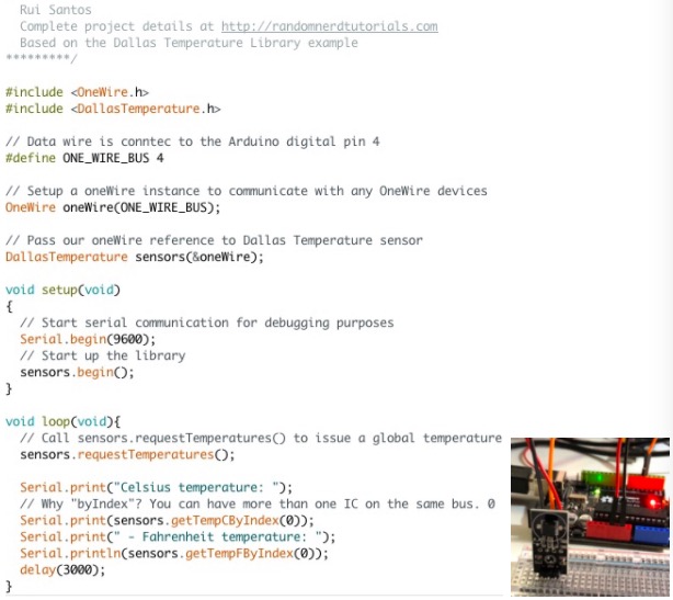
3.2 The DS18B20
I followed this tutorial to use DS18B20.
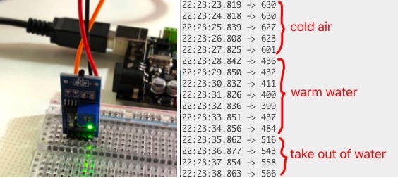
The result:
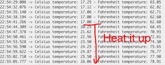
Similar as BH1750 to photoresistor, the DS18B20 provides more accurate result than thermistor. It also provides digital values, but use only one wire. The datasheet provides more detail information.
4. Play with other sensors
4.1 he Hall Sensor
The hall sensor component is similar as the photoresistor, so I use the same connection and code.
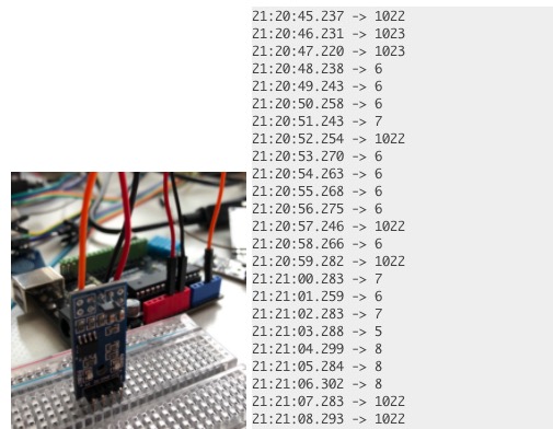
The component has an AO and an DO, however, for both pins the result seems like YES/NO value. I doubt if both the AO and DO pins are DO by mistake. It was not very sensitive either, that I must move the magnet very close to the sensor (<1cm). The earth’s magnet doesn’t have effect at all. I will try to connect the 3144 directly.
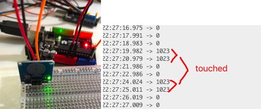
4.2 The touch sensor
The touch sensor has only on/off digital output.
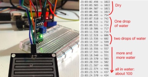
4.3 The rain-drop sensor
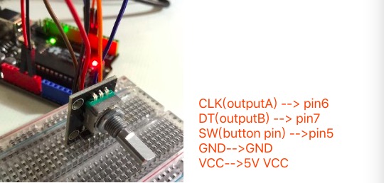
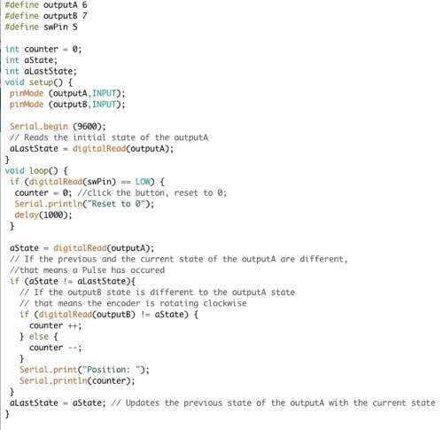
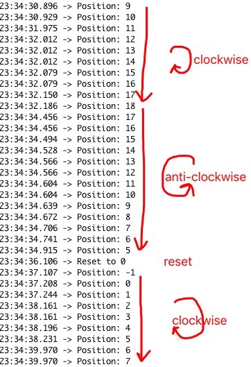
5. The Rotary Encoder
5.1 The experiment
I followed this toturial to play with the rotary encoder:
The connection:
The code (I modified a little to take usage of the button):
The output:
5.2 Understand how Rotary encoder works
I read the introduction about rotary encoder on wiki.
Below is the conceptual diagram. Inner is outputA, and outter is outputB. Black=0 and White=1.
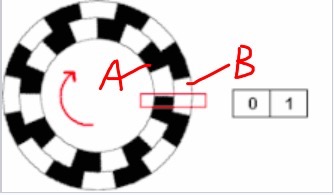
You can find the state change sequences are as below. The row1 and row 3 are detected as aState <> aLastState.And we can see for clockwise, stateB=stateA in row1/3; for anti-clockwise, they are different.
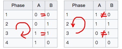
What a clever design! It is REALLY FUN!
6. The Capacity Sensor
The capacitive touchpad inspired me to make an Android style password pad.
I found CapacitiveSensor library in Arduino and learnt the usage from this article.
I didn’t have lab access and had to make the pad by hand.
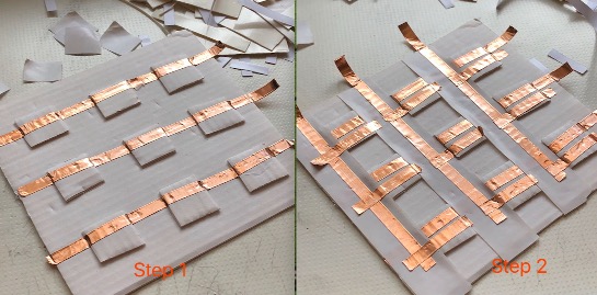
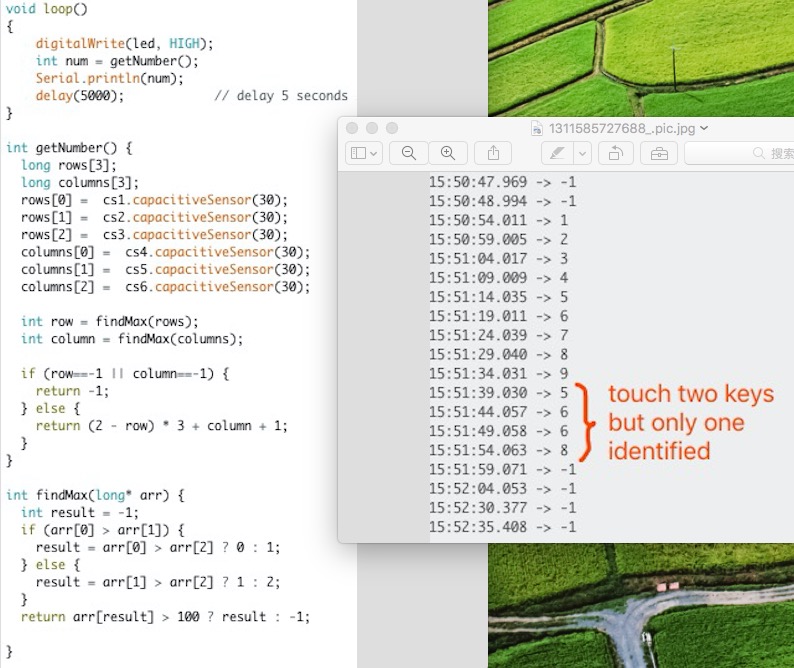
4 pins would be enough for 9 keys. However, as I made the pad by hand, I didn’t want it to be too hard, so I choosed to use 6 pins: 3 for rows and 3 for columns, with connections as below:
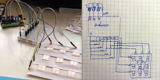
Unfortunately the biggest resistor I have is 680k, but the suggested value is 10M. I tested the resistor value between my fingures, and it was 20M. This is much large than 680. Thus my pad is not very sensitive, however, I found it is still good enough for the code to tell which key is touched. I use the code below to test the pad.
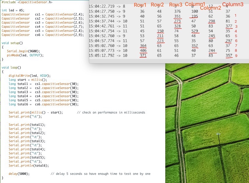
Then I used the code below to convert sensor values to key numbers. If you touch two keys at the same time, the code only detects one. It is good enough for password pad scenario.
Then I added the logic for check password and turn on or off corresponding LED. The password was hard-coded for now, but I will add the persist setting logic later.
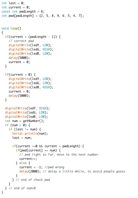
Here is the result. I drew the right password (25896547), the green LED is on. I drew a wrong password, the red LED is on.