Week08. Embedded Programming
This week, I stayed at hom, don’t have PCB board, so can only use bread board to do my experiments. I have an Arduino Uno, an ATtiny85, and a USB converter. I’m using Arduino IDE to simplify the task. Later I will try assembly programming for fun.
Play with ATtiny85 on bread board
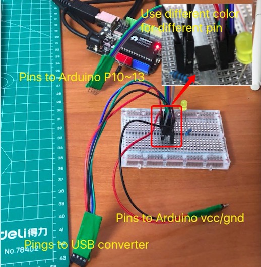
A tip to arrange wires nicely in bread board: different color for different pin, and put them close to the chip. Use tape to group them together. It would be super helpful when you need to plug on and off the wires a lot.
Serial monitor control
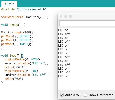
The first experiment I did, was to use Serial Monitor to control LED on and off.
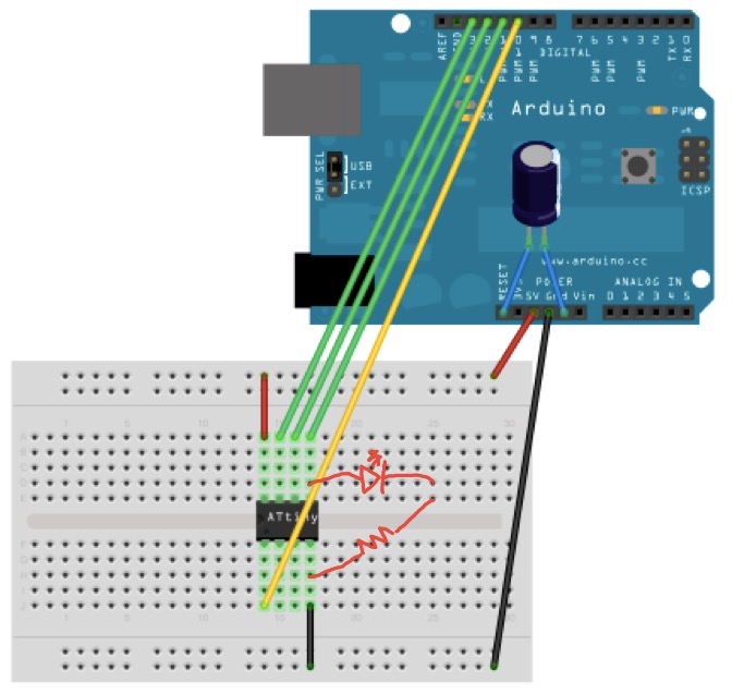
Connect wires as below:
At first the LED was always on. I checked the monitor, and found there was extra character sent after the command char.
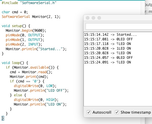
Changed the setting to “No line ending” and it worked fine then.

Three LEDs for fun
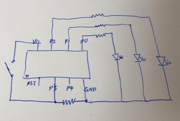
Then I made a program, use a button to control 3 leds.
The circuit:
The code:
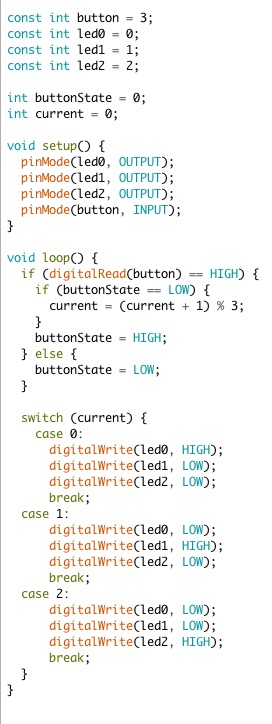
The result:
Work with the datasheet
Three ways to get familiar with ATtiny:
1. follow tutorial and code samples to do the experiments.
2. read header files and even source code. The files are in ~/Library/Arduino15/packages/. You might need “show hidden files” option to find them. For example, the iotn85.h, which provides the definition for ATtiny85, is in ~/Library/Arduino15/packages/arduino/tools/avr-gcc/7.3.0-atmel3.6.1-arduino5/avr/include/avr/iotn85.h; the serial source code can be found in ~/Library/Arduino15/packages/ATTinyCore/hardware/avr/1.3.3/libraries/SoftwareSerial/
3. read the datasheet.
The datasheet for ATtiny25/45/85 is 234 pages long. It’s a heavy task to read it word by word. A better way is to have a glance on the index first, then raise questions and try to find answers from the document.
Below are my questions and answers.
Must Rx/Tx be pin5/pin4? NO!
I followed the step by step tutorial when I play ATtiny85 for the first time. The tutorial uses pin5 for Rx and pin4 for Tx. I found in Arduino, special pins are marked as Rx/Tx. But there is no special Tx/Rx in ATtiny85’s pin configurations.
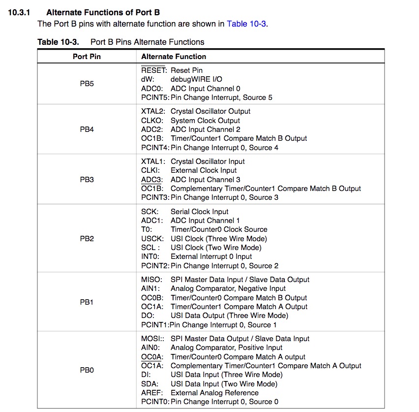
Is it OK to use other pins for Rx/Tx? I modified the pins and the result is YES.
Persist data after power off? Doable!
In my final project, I need to persist data after power off for my clock. Otherwise, people need to set the alarm every time it get plugged out.
So I checked Chapter5, AVR memories, and found it has 512 bytes of data EEPROM memory. It can be write/erase for at least 100000 times, enough to use for setting alarm.
The first thing need to do is to understand the registers. The EEAR/EECR/EEPE/EERE are defined in iotnx5.h, which is used for ATtiny25/45/85 IOs.
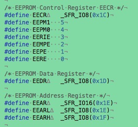
The datasheet specifies the usage of every bit of these registers.
- EEAR: The EEPROM addresses. ATtiny85 has 9 bits for the address (EEAR8 in EEARH and EEAR7:0 in EEARL), so it is 2^9 = 512 bytes.
- EEDR: The EEPROM data register. For write operation, contains the data to be written to EEPROM; For read operation, contains the data read out from EEPROM.
- EECR: The control register.
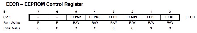
- EEPM1 and EEPM0: 0,0 means erase and write; 0,1 means erase only; 1, 0 means write only.
- EEMPE & EEPE: 1, 1 means EEPROM program enabled. EEMPE is used to control EEPE. They will be reset by hardware after few clock cycles.
- EERE: The read enable signal. (I believe it will be reset by hardware too)
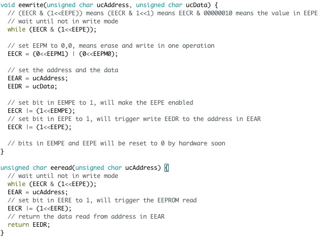
Read the bitwise operators in C to understand the meaning of these operators.
The code to read/write EEPROM is explained as below:..
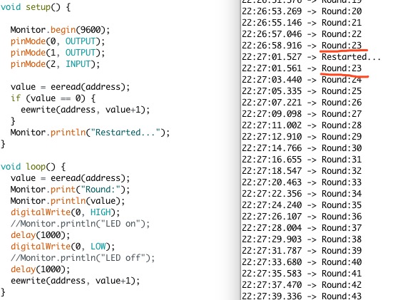
I use these functions to read and write a char value, to record how many times the LED had been turned on and off. I plugged out the battery and put back again after round23, and the Serial Monitor showed that it restarted with 23, which means the value is persisted after power off.
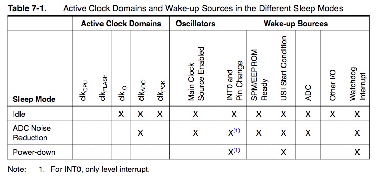
Use sleep mode to save power? Doable!
In my final project, I would like it consumes less power, so I was excited when I found the Sleep Mode chapter in the datasheet.
However, there was no sample code in this chapter. I searched and found this example, modified a little bit, as below:
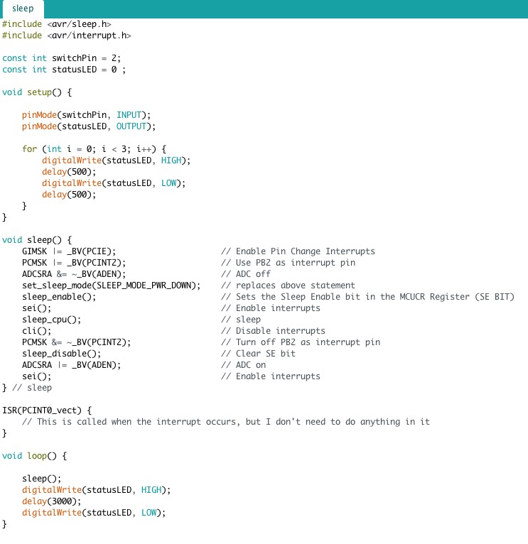
Then I read the head files of sleep.h and interrupt.h, which can be found in ~/Library/Arduino15/packages/arduino/tools/avr-gcc/7.3.0-atmel3.6.1-arduino5/avr/include/avr.
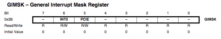
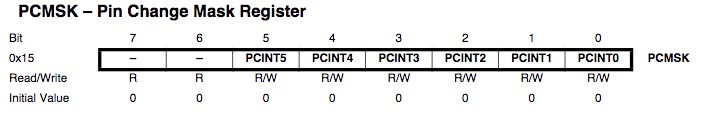
The register description in datasheet chapter 9-interrupts are useful.
The circuit is as below, button in pin2 and led in pin0:
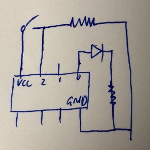
The result: at the beginning, the LED flashed three times. The the chip went to sleep. Touched pin2 with wire from vcc, the chip waked up and LED turned on for 3 seconds, then went to sleep again.