Week04. Electronics Production
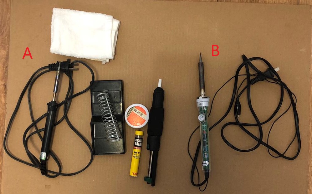
Still unable to go to lab this week. Lucky I found two soldering irons and some other tools at home, so I decided to postpond the PCB cutting task, doing the solder tasks, and learn more electronic knowledge in advanced.
What to solder? I ordered many components, a few practice board, and also a few DIY sets from taobao. Unfortunately, due to the Coronavirus disease, the delivery is super slow, and they are still not arrived yet. So I have to find something in my home to solder.
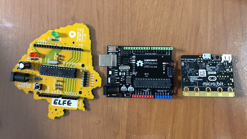
I found some components in an Arduino set, but there is no PCB board. Then I decided to desolder something and solder back again. I have a Shanghaino which I made last December in Fab’s workshop. However, I don’t want to repeat the work. The other boards such as UNO and micro:bit are too small. The electoric components in household electrical appliances are also too small.
Finally, I decided to use soldering iron A (20W simple iron) to disassemble iron B (60W Adjustable Electric Soldering iron), and assemble back again. Using a soldering iron to solder a soldering iron, it sounds cool, right? And this was a good opportunity for me to learn real electronic ciruits.
Use a soldering iron to solder a soldering iron
STEP 1
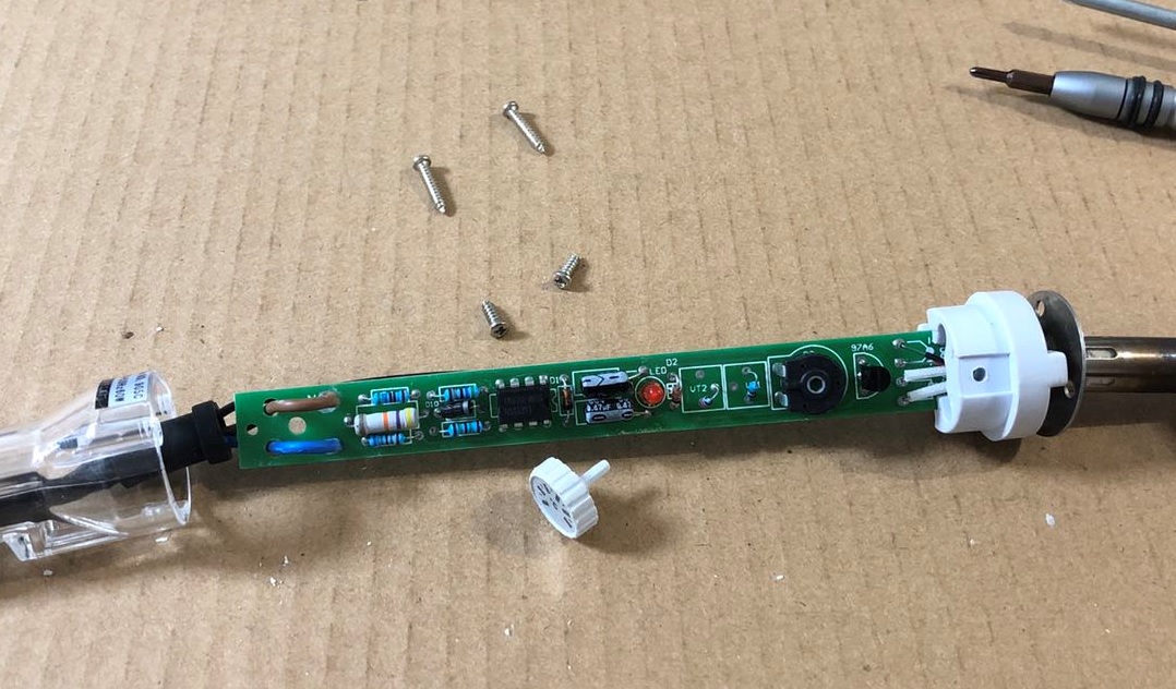
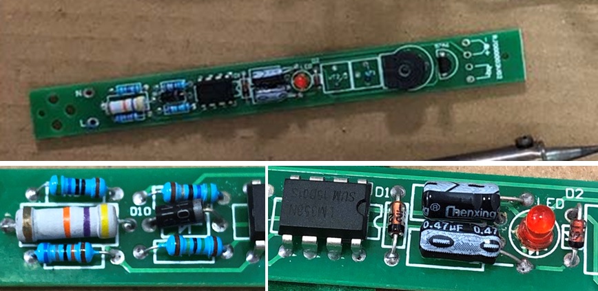
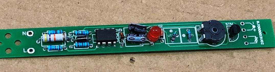
Unscrewed the shell and took a close look at the board. Google these components, to get a brief understanding about how the adjustable iron work. However, some traces were under the components, and cannot be seen clearly. I didn’t got a complete picture of the circuit until I removed all components.)
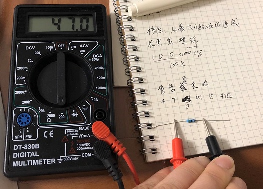
I leart how to use digital multimeter, and I also leart how to tell the resistance from colored circles.
STEP 2
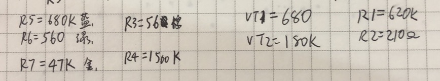
Desoldered the wires first, then desoldered each components, from side to the middle. It’s very importanat to capture record the positions of resistances, and also the directions of the diode and capacitances. So I took more close photoes, and also recorded the values on paper.
It took a while to get the components off. The desoldering pump was too big and I can hardly operator with it by single hand. I found using tweezer together with iron to pull the components out were easier.
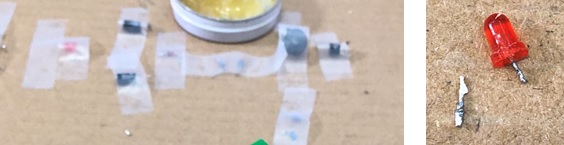
Finally, the 9 resistances, 2 capacitances, 3 diodes, 1 bidirectional thyristor, 1 regulation resistance, were all desoldered successfully. I use tapes to keep their position. One of the LED’s leg is broken. Lucky that I have new LED. Then I didn’t desassamble the IC, as some of its legs also seemed to be fragile, and I didn’t have a new one.
STEP 3
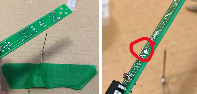
The pump did not remove all the tin, and some holes were blocked. So I have to clear the board before re-soldering. Tried several ways and I invented this method:
- fixed a pin on the table, the sharp pinpoint facing upwards.
- hold the board above the pin, carefully aim the blocked hole on the pinpoint. Then put the iron above the board to desolder the blocked hole.
- As the heat makes desoldering, the pinpoint drills the blocked hole.
- Raise the board quickly, and it will leave the tin above the hole (red circle below), and can be cut easily.
STEP 4
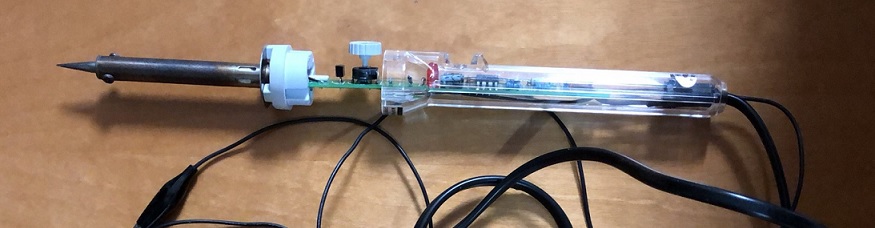
Soldered the components back.
It was harder than soldering a new component, as the legs were cut already, and there were tins left on the legs too. However, I managed to do this
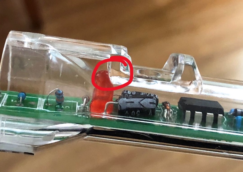
The only problem was: the new LED was too large, and I cannot put the board back into shell:
STEP 5
Test!
Pluged in the socket, the LED turned on, and the iron was hot a few seconds later. Seems everything is fine. I will try to find a smaller LED to replace this, and make the iron usable again.
Learn the circuits of Adjustable Electric Soldering iron
I found the circuits from this artile.
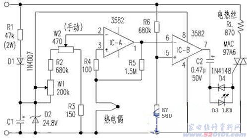
Comparing with the drafts I draw while desassambling the iron, I learnt how the adjustable electric soldering iron works.
The next stpe is to draw the PCB design file. I’m learning the electronic design now, and I will try make the file by EAGLE later.