11. Input devices
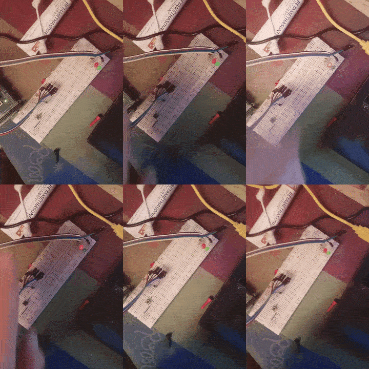
For this input project, we are going to plug 2 LEDs to the digital outputs of the Arduino and have them turn on dependings on the light level in the room.
If the potentiometer gives a dark value (high resistance) then the red LED will blink. If not, then the green one will turn on.
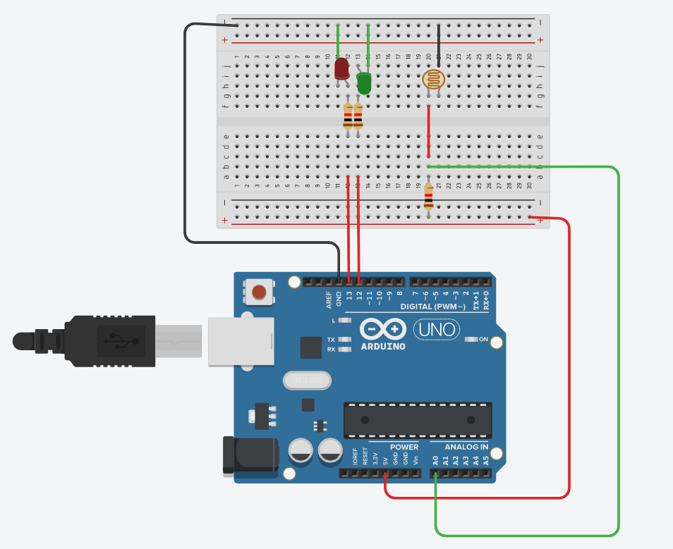
We have made the following connections:
We have added another resistor in series to the photoresistor because this is the only way to measure the voltage. The Arduino does not give us the option to measure the intensity of the current, so we will deduct it from adding the extra resistor
We write our code
int red=13;
int green=12;
int sensor=A0;
int voltage;

void setup() {
  pinMode(red, OUTPUT);
  pinMode(green, OUTPUT);
  pinMode(sensor, INPUT);
  Serial.begin(9600);

}

void loop() {


  voltage=analogRead(sensor);
  Serial.println(voltage);
  if (voltage > 800) {
      digitalWrite(red, HIGH);
    } else {
        digitalWrite(green, HIGH);
      }

  delay(250);
  digitalWrite(green, LOW);
  digitalWrite(red,LOW);
}
And it works 
Remote control
Let’s try to use remote controls with our projects.
For this project, we will connect the IR sensor to the Arduino - the 3 letters on the PCB mean: G = Ground, R = Red = VCC, Y = S = Signal. We just connect 5v, Ground and the signal pin to the 7th pin.
We write our code :
#include <IRremote.h>
float value;

// Define sensor pin
const int RECV_PIN = 7;

// Define IR Receiver and Results Objects
// IRrecv irrecv(RECV_PIN);
// decode_results results;


void setup(){
  // Serial Monitor @ 9600 baud
  Serial.begin(9600);
  pinMode(RECV_PIN, INPUT);
  // Enable the IR Receiver
  // irrecv.enableIRIn();
}

void loop(){
  value = digitalRead(RECV_PIN);
  Serial.println(value);
  delay(500);
//    if (irrecv.decode(&results)){
  //      Serial.println(results.value, HEX);
    //    irrecv.resume();
  //}

}
Now the Serial Monitor shows us the signal received from IR remotes.
Tilt switch
We use a tilt switch. The connections are the same: G = ground, R = red = VCC, Y = S = signal
Our code:
const int pin=2;
int value;

void setup() {
  Serial.begin(9600);
  pinMode(pin, INPUT);
  digitalWrite(pin, HIGH);
}

void loop() {
  value = digitalRead(pin);
  Serial.println(value);
  delay(250);
}
Now the serial monitor can show us when the switch is tilted
