# Group assignment
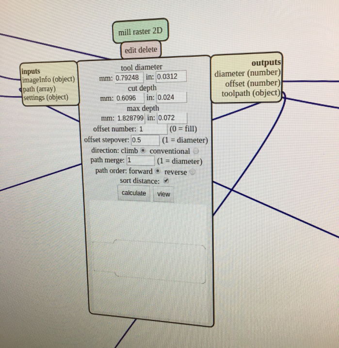
This week's group assignment was to characterize the design rules for our PCB process. We made a few attempts at milling the provided line test on our Roland SRM-20, using these settings:
Pretty standard: 1/64th inch bit for milling traces...
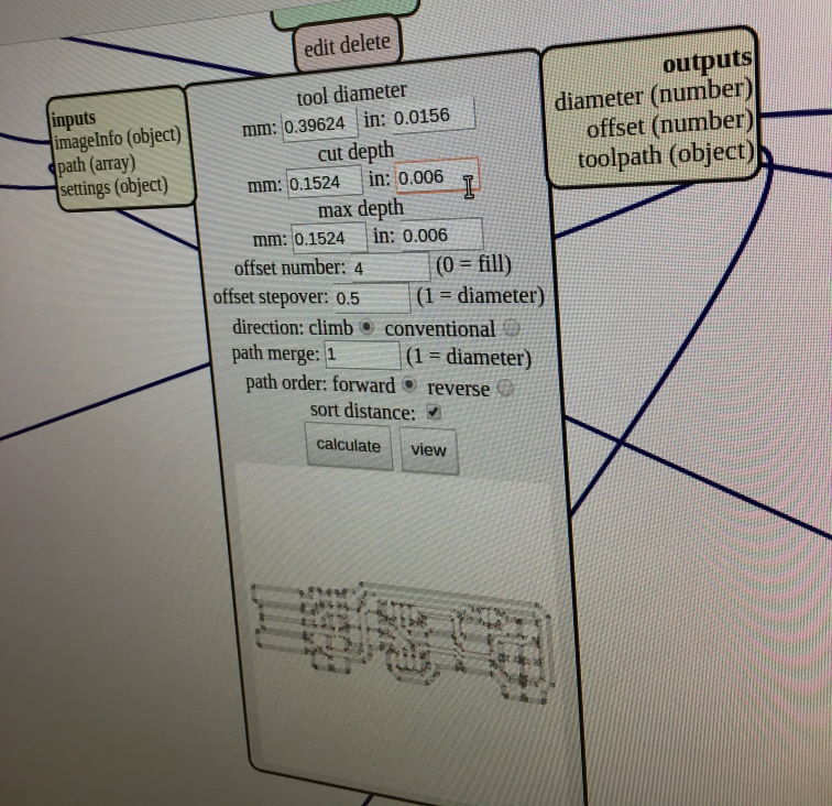
and 1/32th for cutting the outline.
Inital results with both bits for comparison:
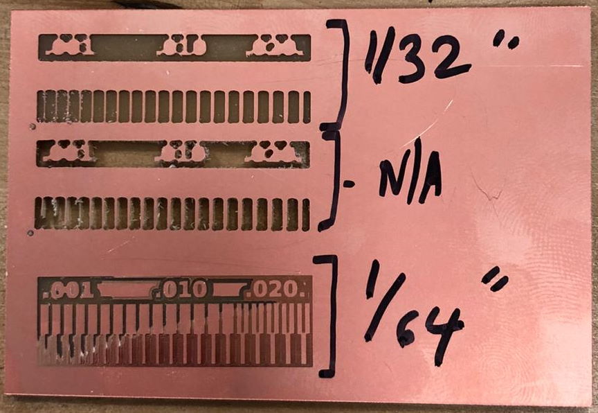
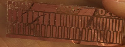
This was a decent first try but we eventually tested the 0.01" bit for added precision. After a few false start and broken bits, turning down the speed (to "2" - what is the unit here?) in Mods helped and we eventually got some pretty good results! (excuse the terrible picture here!)
# Individual assignment
This week's individual assigment was to make an ISP (In System Programmer).
# Exploration
I already have some amount of experience with both circuit design and PCB production, namely while building this kludgy mess:
Which did give some pretty nice results:

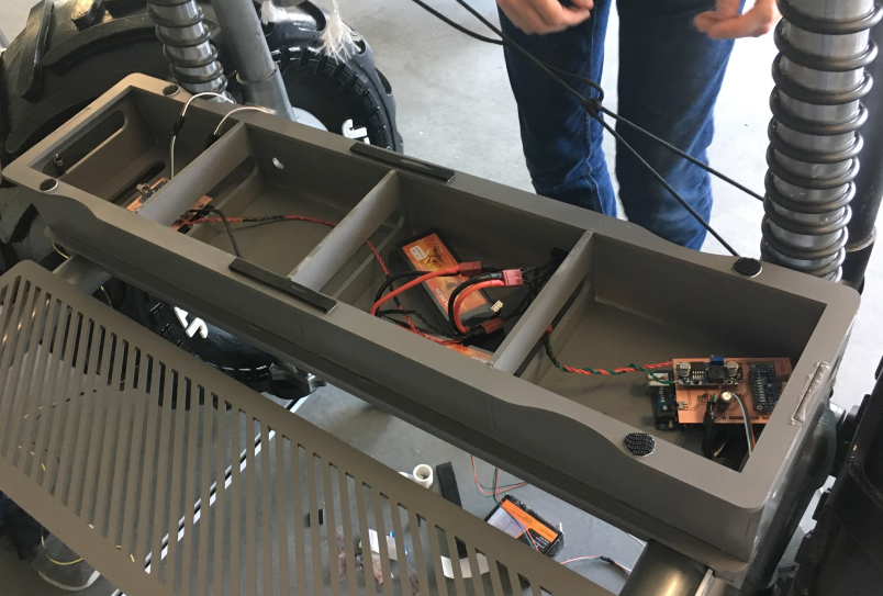
And this slightly less hackish design:
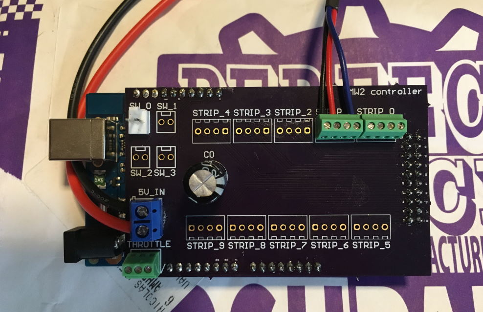
to power our second Magic Wheelchair build:
Based on this, I figured I would use this week (and, as it turned out, the next week!) to explore a little beyond the standard FabISP so I went looking for information about UPDI ISPs.
First, why UPDI instead of the usual AVR ISP? It looks like UPDI is used by the newer generation of ATTiny microcontrollers. Why would we want to use those? E.g., why go for a newer generation ATTiny over the classic ATMega328p around which the Arduino Uno R3 is built?
Figuring this out without spending countless hours reading datasheets turned out to be less obvious than one might hope. I finally landed on some useful resources:
- http://www.technoblogy.com/show?2OCH
- https://jaycarlson.net/pf/atmel-microchip-tinyavr-1-series/
- https://hackaday.io/project/165881-attiny-1-series-with-arduino-support
To summarize some of those resources, my impression is that the new 0-series and 1-series ATTiny range provides micro-controllers that are:
- cheaper (under $1 each even in low volumes)
- smaller (as in a physically smaller package)
- easier to integrate
- the internal clock seems to be way more accurate, removing the need for an external crystal - in fact, the ability to connect an external clock seems to have been removed entirely
- the peripherals are more consistent across the range of chips, and more numerous (i.e. more timers, capacitive touch sensing controller built it, etc.)
Based on this, I figured it would be worth making a simple UPDI ISP. This week's recitation offered this simple design: http://academy.cba.mit.edu/classes/embedded_programming/FTDI/USB-FT230XS-UPDI.png http://academy.cba.mit.edu/classes/embedded_programming/FTDI/USB-FT230XS-UPDI.traces.png http://academy.cba.mit.edu/classes/embedded_programming/FTDI/USB-FT230XS-UPDI.interior.png
The BOM is extremely simple, which was also attractive:
- 1x FT230XS IC (datasheet) - an all-in-one USB-serial UART
- 1x 2 pin header
- 1x 1uF capacitor
- 2x 10pF capacitor
- 2x 49Ohm resistor
- 1x 4.99kOhm resistor
The FT230XS is a 16 pin SSOP packaged IC, which might be a little fiddly to solder. Thankfully, most of the pins are actually not connected. No schematic is provided (that I could find?) but a quick glance at the board layout shows that only VCC, ground, USB+, USB-, transmit and receive are used. Furthermore, connecting the output of the board is even simpler; since UPDI is a one-wire protocol, TX and RX are simply connected together to the single UPDI data line!
I spent a little time exploring the datasheet and looking at the application notes, mostly so I could figure out what these components do and if they are the right values, or if they can be replaced with something close based on availability.
Here's what that investigation turned up:
- 1x 1uF capacitor => de-coupling for VCC; the datasheet seems to sort of disagree on that value, more below
- 2x 10pF capacitor => de-coupling for data lines (USB+, USB-). The datasheet suggests 47pf, it's likely that anything in the 10-100pF range will do
- 2x 49 Ohm resistor => current limiting on data lines; datasheet suggests 27 Ohm, anything below 400 is probably fine
- 1x 4.99k Ohm resistor => used to tie TX to the single data line in UPDI (RX uses no resistor). Why? I'm not sure, but the tiny bit of documentation for pyUPDI seems to agree (at 4.7k Ohm) so let's do that!
TIP
All of the SMD resistors and capacitors in the lab appear to be 1206 packages. This will become important for electronics production when picking components in ECAD!
There are also several design decisions that might be worth investigating in this tiny example board, as compared to the datasheet, specifically the "USB power configuration" section on page 22:
- as always with ICs in electronics, in my experience, the power part is the real challenge here. The datasheet uses a significantly more complex configuration than the single 1uF capacitor:
- a 10nF capacitor in front of a ferrite bead
- a 100nF capacitor and a 4.7uF capacitor in parallel between VCC and GND after the ferrite bead. I'm assuming the datasheet expects these to be power and ground planes in a more complex design
- the reset, VCCIO and 3V3OUT pins are tied together, and then de-coupled from GND through a 100nF capacitor
The simplifications made on this design should probably be okay. I was a little concerned with RESET being unconnected, which I assumed could lead to spurious resets, but page 15 of the data sheet actually says that it can also be left unconnected (as an alternative to tying it to VCC) if unused, so we should be fine!
With all of this investigation done, it seemed like this design (which has a lot less documentation on the FabLab side) was reasonable and stood a chance of working, so off to manufacture it we went!
Even though I've milled PCBs on our Roland SRM-20 before, this was still a learning experience due to the small size of the traces... and due to forgetting lessons of the past, to be honest, which this detailed log will hopefully remedy for the future:
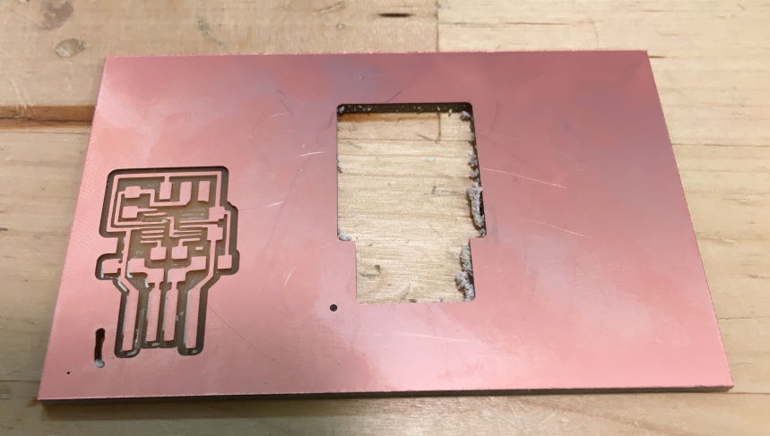
- 1st attempt, 1/32" bit: fixture not sufficient, straight lines came out blurry; lifted off during outline cut
- 2nd attempt, 0.010 bit: bit appears broken, results were worse than a bigger bit. Broke another bit (new, better looking) bit despite reduced cut depth... may need to reduce speed but I don't want to break yet another bit.
- 3nd attempt, back to 1/32": stock held to spoil board better, okay results despite very fine traces on this design. Tried conventional cutting instead of climb, reduced speed to 2mm/s; this appears to have limited the issue with traces being ripped from the board
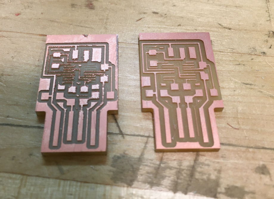
The 3rd attempt is hopefully good enough to solder!
I was initially hoping to avoid hand soldering most of the components on since I own a reflow station. Unfortunately, I had forgotten one small detail: solder paste expires. I'm actually quite amazed this worked for the Magic Wheelchair electronics last year, considering:
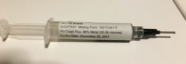
Thankfully, hand soldering this board was still reasonably doable:
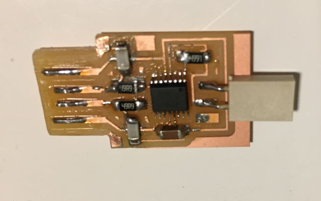
With the board populated, it was time to actually test it!
The board was immediately detected by Windows, which was encouraging. Some drivers were needed for the UART chip but they were easily found on FTDI's website.
TIP
On Windows, I actually had to manually install the drivers twice from the Device Manager; once for a deice detected as a USB-serial converter, and then once for the COM port that showed up.
The next step was to install pyUPDI, as suggested in the course material. Note here that the dependency to install for it is PySerial, not just Serial, i.e. pip install pyserial, NOT pip install serial!
Finally, since I don't actually have an ATTiny board to program, the best I was able to do so far was to run pyUPDI while hooked up to an oscilloscope:
It's alive! More testing is needed but at least something is happening on the UPDI pin.
# Learning results
- I'm quite proud of the results of the laser cut PCB attempt. It remains to be seen if the board actually works (electrical continuity testing seems to say it should - my inability to program the ATTiny for now may be the result of user error, poor circuit design, etc) but the results are quite promising!
- I'm excited to explore vinyl cutting as a future option, especially for simple but large PCBs. I have a project idea I've been meaning to work on for a while (an updated version of a Word Clock design I made years ago) that would really benefit from the ability to make a PCB at a size that would be prohibitively expensive to have professionally fabed.
- I am also extremely interested in exploring 2 layer board fabrication in the future; some of the ideas raised in the lecture (rivets for vias, registration for double sided milling) are intriguing and will need further work!
For future investigation, here are a collection of links and information I want to dig deeper on:
Investigate:
- programming: https://hackaday.io/project/165439-attiny-0-series-programming-on-the-cheap
- Different UPDI programmer, much more complex, based on a full ATMega328p instead of just a USB-serial UART; uses jtag2updi
- Programming from an Arduino Nano + debugging: https://github.com/SpenceKonde/megaTinyCore/blob/master/MakeUPDIProgrammer.md
Things to try:
- Double sided PCBs: http://sibusaman.fabcloud.io/doublepcb/
- Laser cutter: http://fabacademy.org/2019/docs/FabAcademy-Tutorials/week04_electronic_production/fiber_laser_pcb.html
- PCB rivets basics: http://fab.cba.mit.edu/classes/863.16/doc/tutorials/PCB_Rivets/
- More info on rivets to buy (I got some really basic ones from Amazon for now, this looks like a better process though): http://www.oz4.us/2017/07/howto-rivets-for-double-sided-PCB.html
- Update: rivets from the internet either take too long to get here for my patience, or are only available in inconvenient sizes; try this instead? https://retromaster.wordpress.com/2009/08/18/the-pcb-via-press/
Possible sources for PCB designs for an ATTiny412 breakout board:
- datasheet
- https://github.com/vladbelous/avr-attiny412-boosted
- https://www.tindie.com/products/leonerd/attiny412-development-board/
- https://www.tindie.com/products/drazzy/attiny412similar-breakout-board-bare-board/
Useful finds:
- One of the articles linked above led me to this interesting blog about micro-controllers that goes beyond the basics of Arduino (which is a great platform but also full of vague, incredibly basic content sometimes). In particular, this post https://jaycarlson.net/microcontrollers details some of the modern options for microcontrollers under $1.
- This interesting application note for the ATTiny1617 drives some WS2812B (NeoPixels, i.e. programmable RBG LED strips) directly from the MCU by using its integrated CCL (Configurable Custom Logic), which sounds like a promising way to drive these at the lowest possible cost and power requirement (which might be moot considering that the power requirements of LEDs would dwarf that of pretty much any MCU anyway, but still)