18 & 19. Machine Design and Mechanical Design
Group Assignment
- Design a machine that includes mechanism+actuation+automation
- Build the mechanical parts and operate it manually
- Document the group project and your individual contribution
- Actuate and automate your machine
- Document the group project and your individual contribution
We decided collectively to make a CNC capcake batter machine that would automatically filled the molds of the capcake tray. I was tasked with designing and producing the mounting system to hold the capcake batter dispenser and actuate the trigger to open the dispenser. Since the fab lab wasn’t open yet, I could only produce a rough CAD model. The design is fully parametric, allowing me to adjust the model to real life parameters.
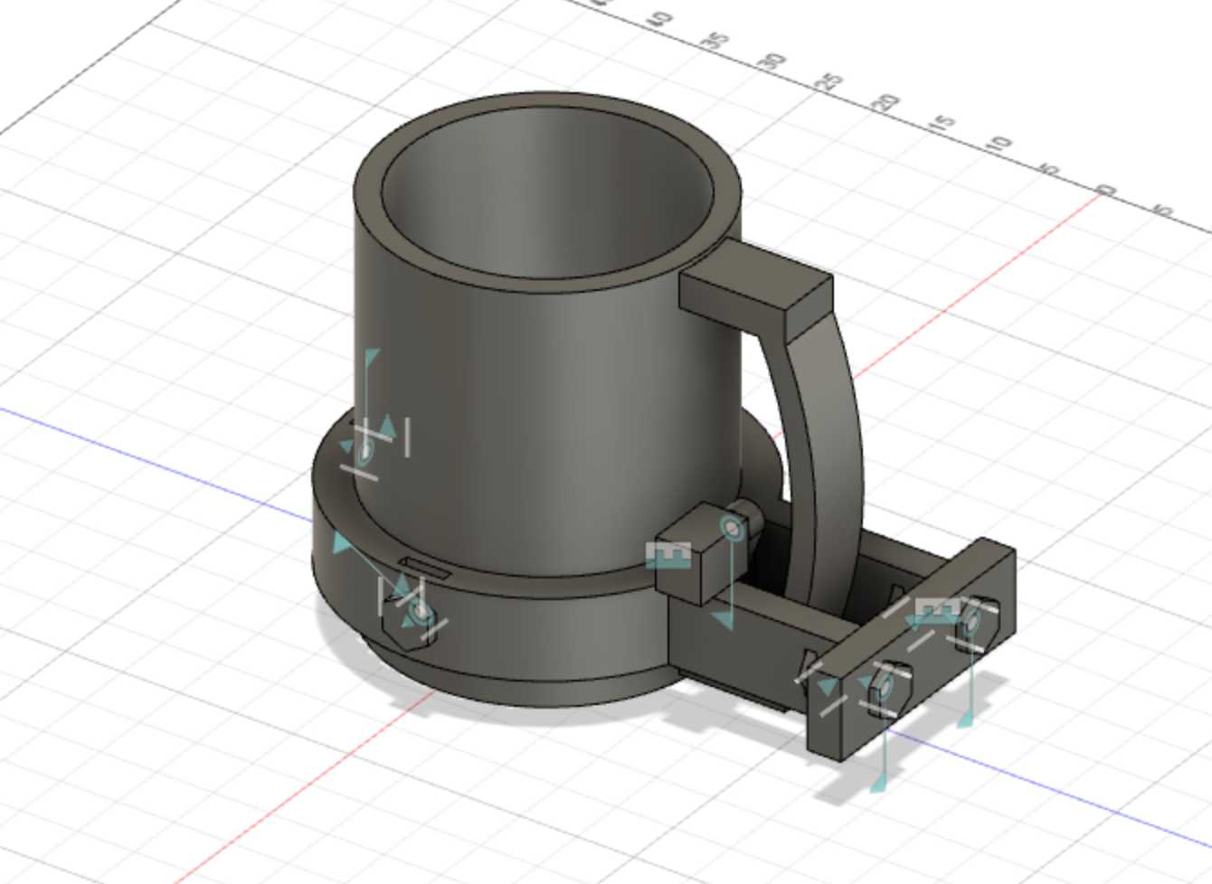
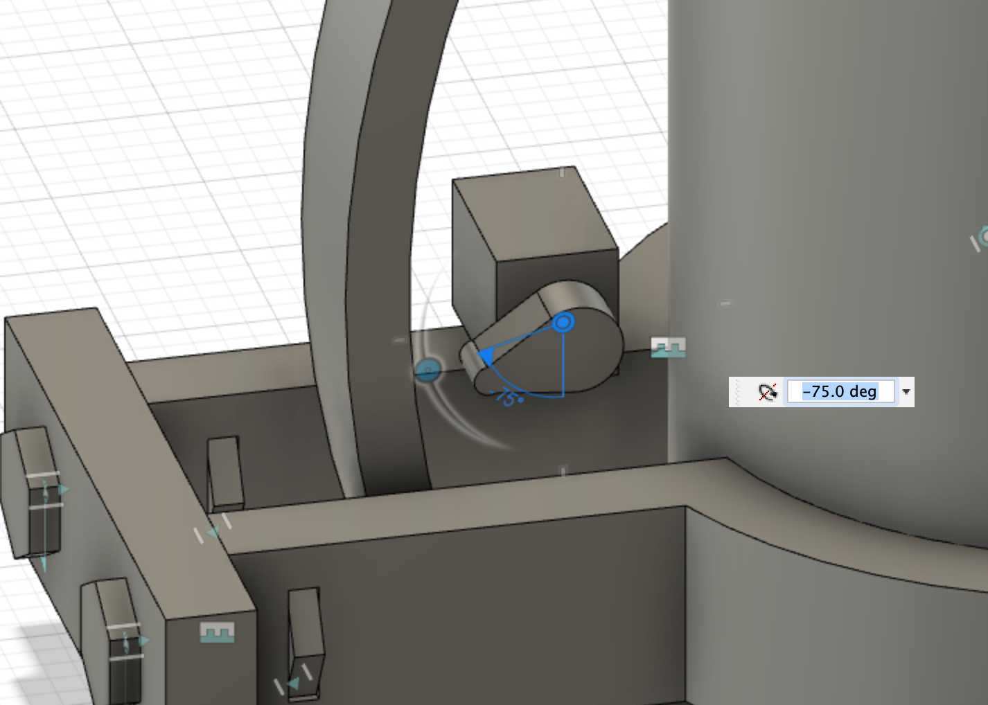
I decided that having a servo that pushes the trigger in would be a very simple actuation mechanism. However, Dr. Fagan brought valid concerns about the strength of the servo and, instead, recommended that a motor turn a pipe fastener to pull the trigger.
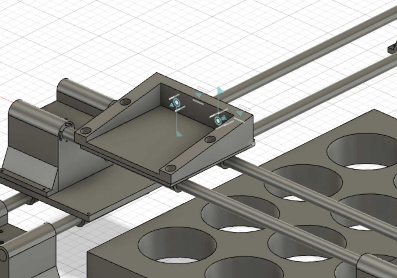
To attach the mount to the gantry, I decided to add a base plate near the baack of the handle and used a mounting mechanism that I used when I built a 3d printer from scratch. Dr. Fagan told me that this method was quite common to attach two things together. However, the group members responsible for greating the gantry system are were still working on the gantry system and could not provide a mounting mechanism for the base plate.
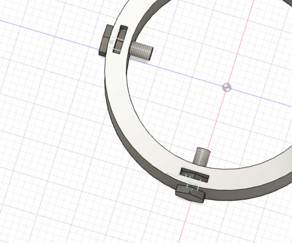
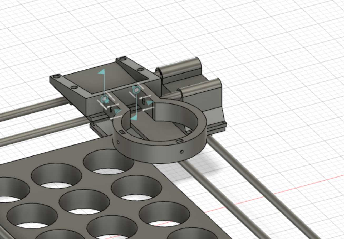
Since the mount would not be exactly the radius of the capcake dispenser due to overhead and tolerances, I added two bolts that would clamp down towards the cupcake dispenser. This mechanism was another mechanism that I had observed in real life applications.
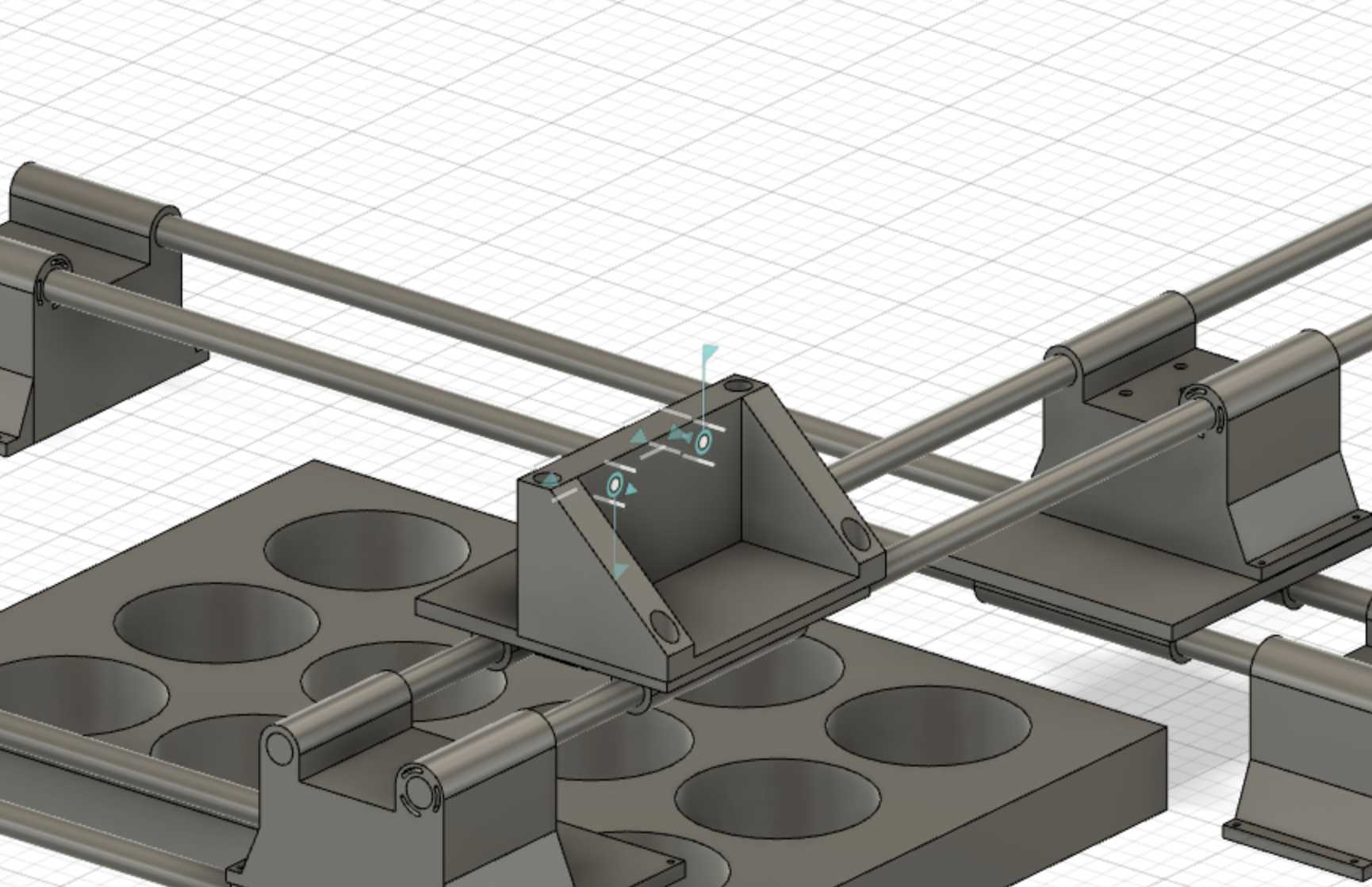
Now, I had to design the adapter to connect the mount to the gantry plates. I imported the gantry CAD files from my other team mates, however, I realized that the gantry model was not an assembly. This would make it harder to emulate real life constraints and model my adapter. I reconstructed the gantry model as components with realistic joints and built my adapter on the the new assembly,
I jointed my mount model to the adapter to ensure a perfect fit.
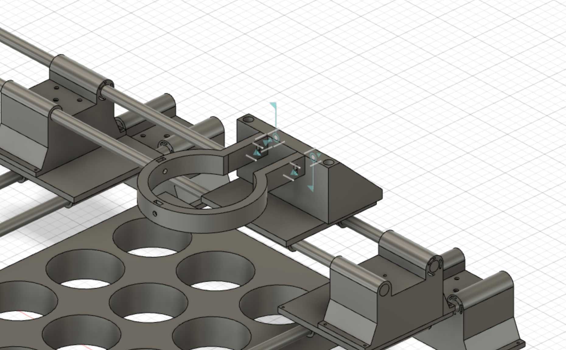
However, my team members advised that the adapter was backwards as the dispenser would be mounted on the side of the plate with the mounting holes further away. I redesigned the adapter with the changes in mind. I had to increase the height of the adapter because the recessed nature of the adapter meant that space was requried for the dispenser handle.
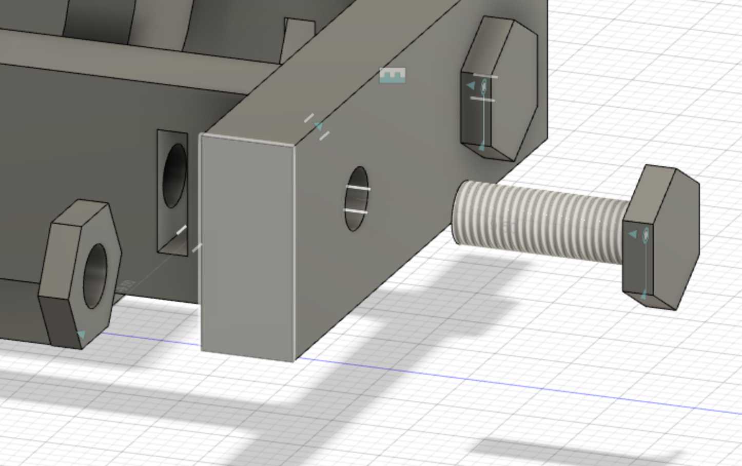
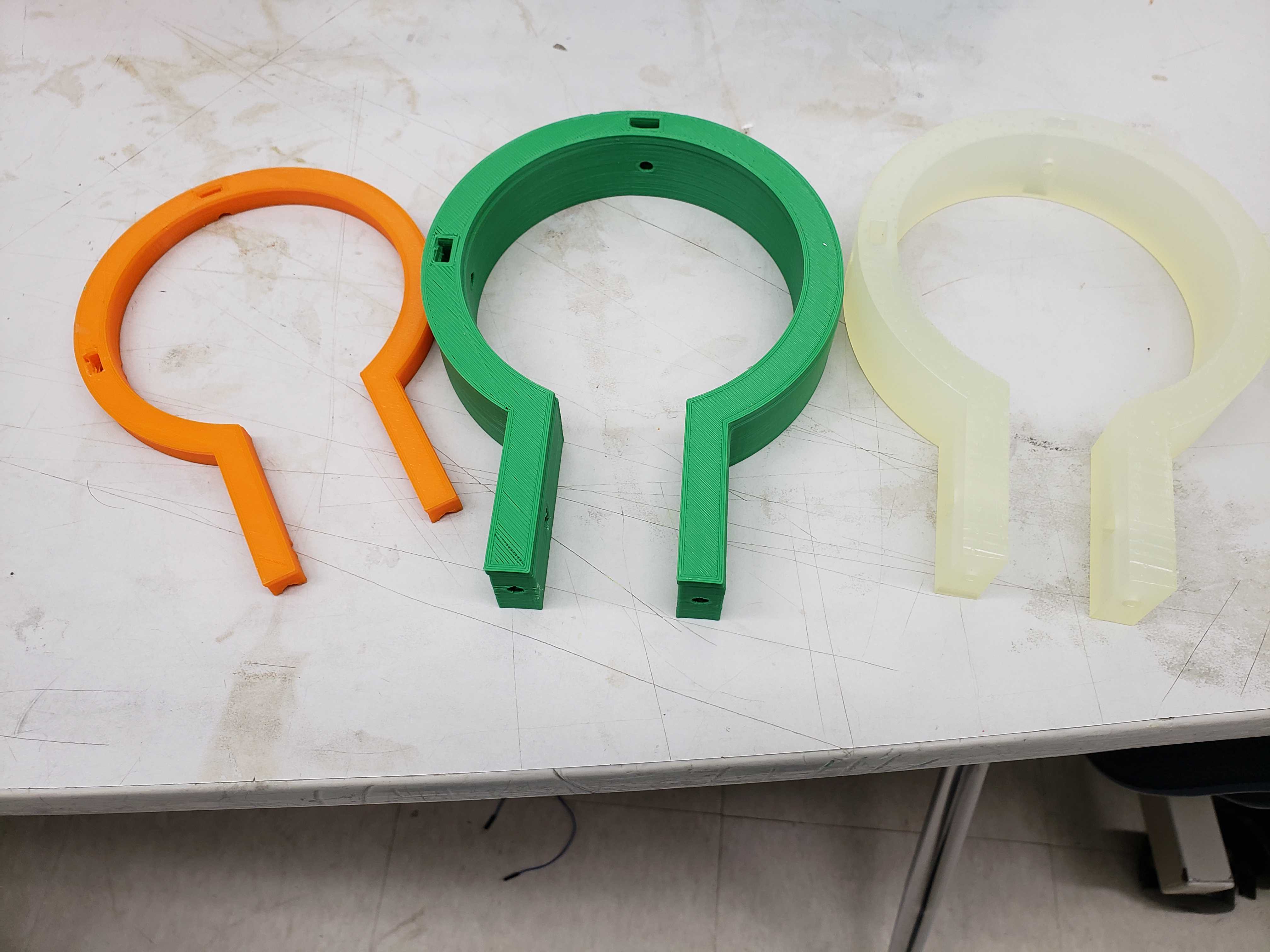
With the CAD models doen, 3D printing the mounts with the correct tolerances proved to be another challenge. The first print was found to have slot too big for the nut to reasonably fit snugly into the slot. In addition the first print took about one day to print. The second print was found to have a slot too small for the nut. However, the printing time was reduced to 4 hours due to reduction of height, thickness, and diameter parameters of the mount. Only on the third print, did the print contain the correct tolerances.
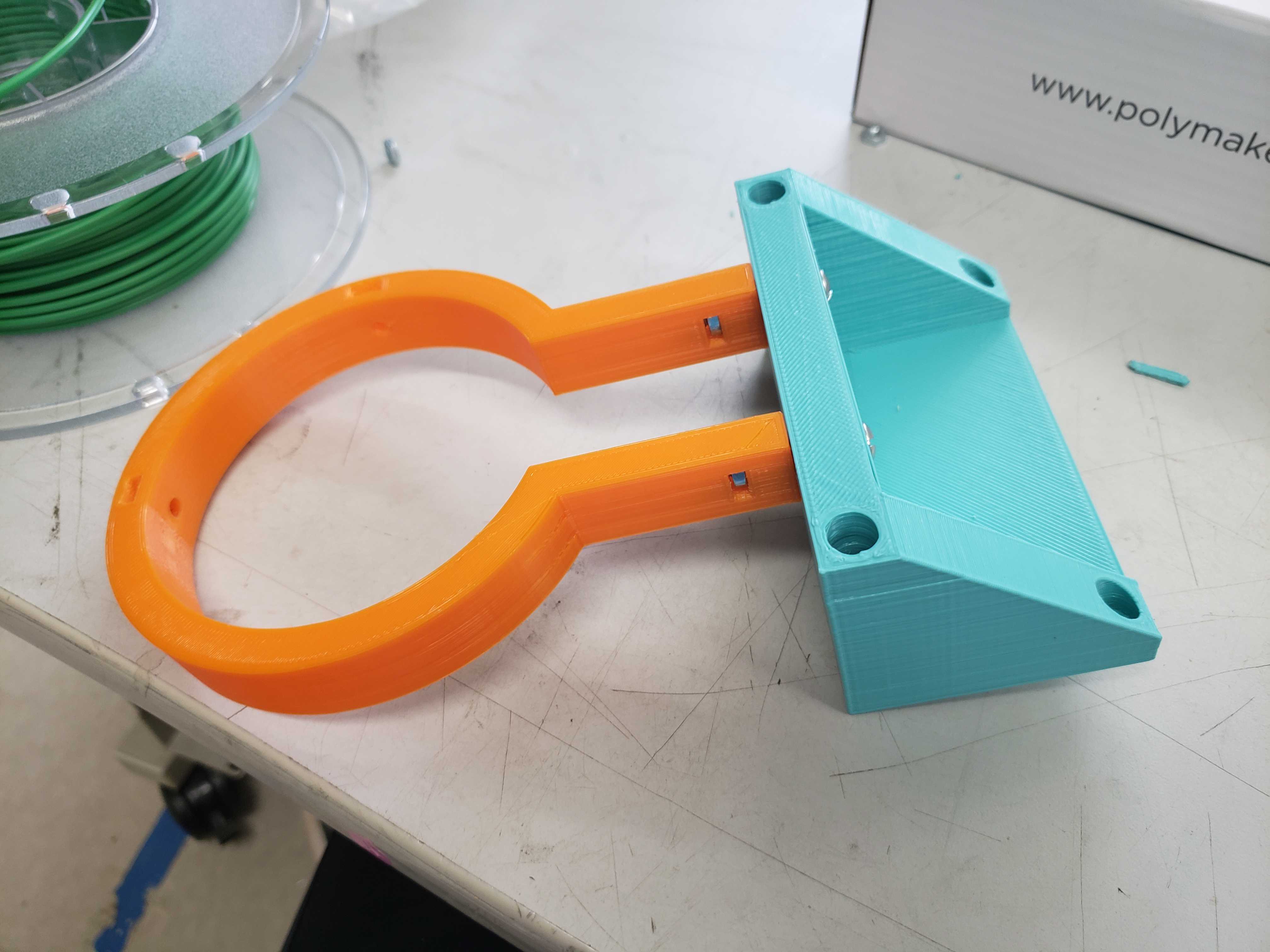
After printing out the adapter, I was able to connect the two pieces together with nuts and bolts.
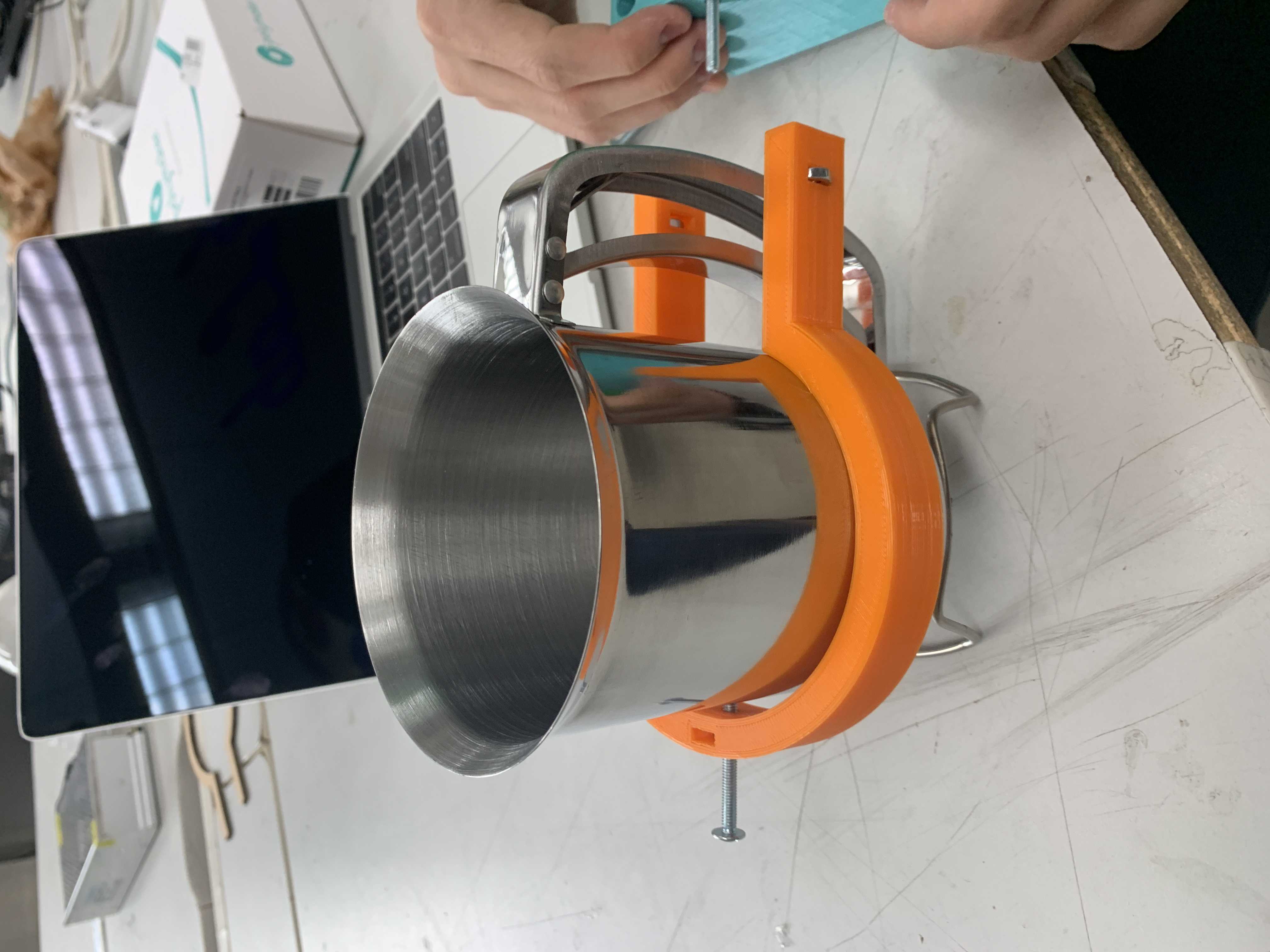
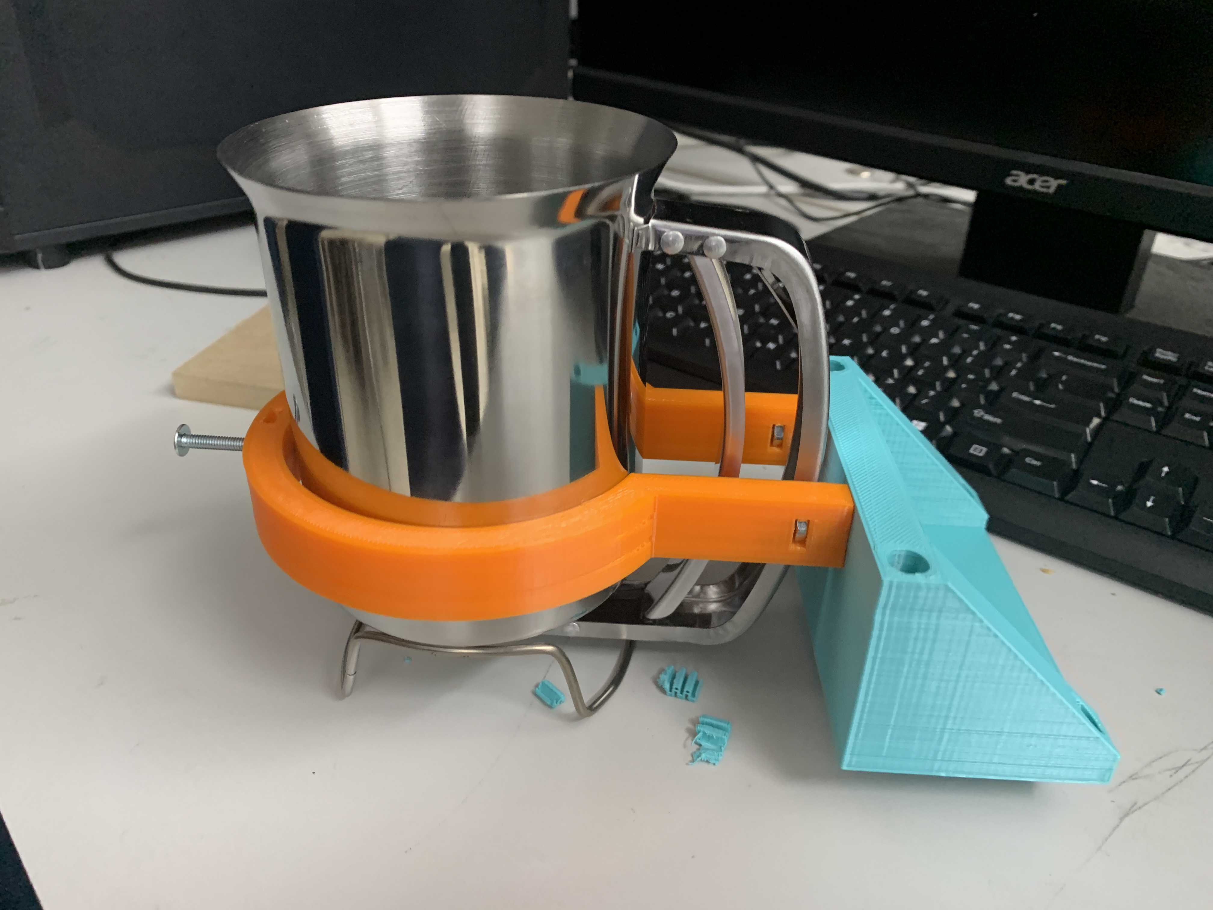
In addition, the dispenser fit perfectly into the mount and adapter.
As the rest of the time finished their individual contributions to the group project, I helped assemble the individual pieces into the finished project. This required designing and laser cutting a base plate to attach the brackets, attaching pieces with nuts and bolts, attaching belts to the plates, and making modifications to the brackets to allowing servo to fit through.