7. Electronics design
Group Project:
- Use the test equipment in your lab to observe the operation of a microcontroller circuit board
Individual Project:
- Redraw an echo hello-world board,
- Add (at least) a button and LED (with current-limiting resistor)
- Check the design rules, make it, and test it
- Extra credit: simulate its operation
PCB Design
We decided to use EAGLE to design our PCBS as it was readily available with the student subscription to Autodesk. Since we had no experience using EAGLE, we decided to follow the Sparkfun tutorial that Fab Academy alumni had used in the past.
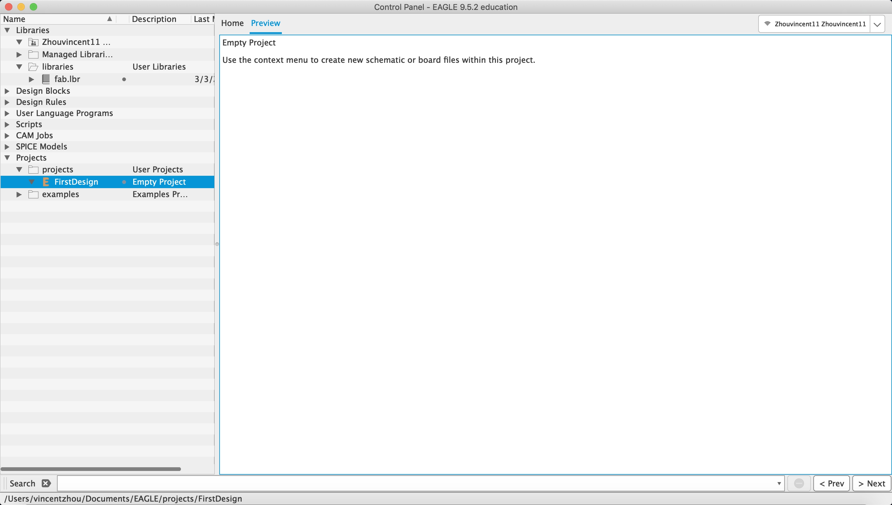
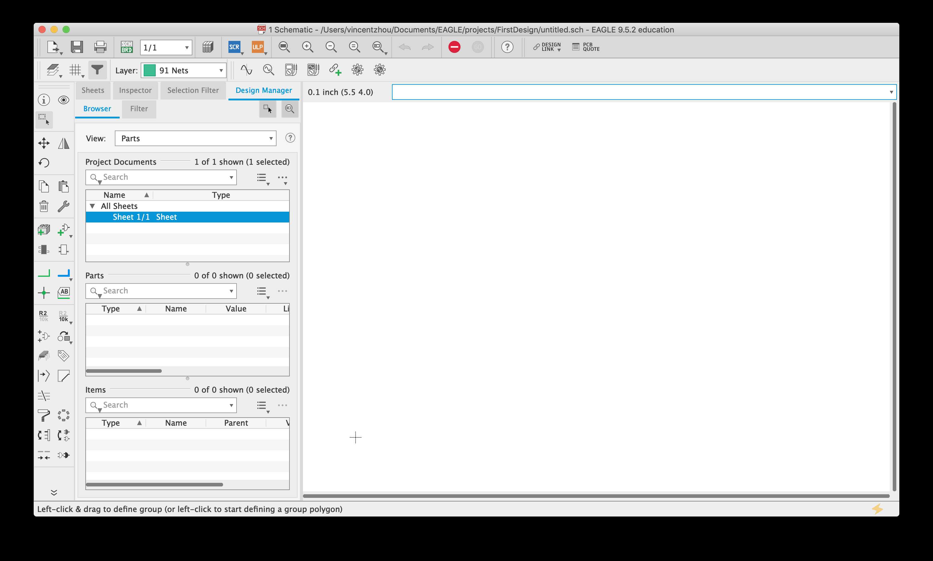
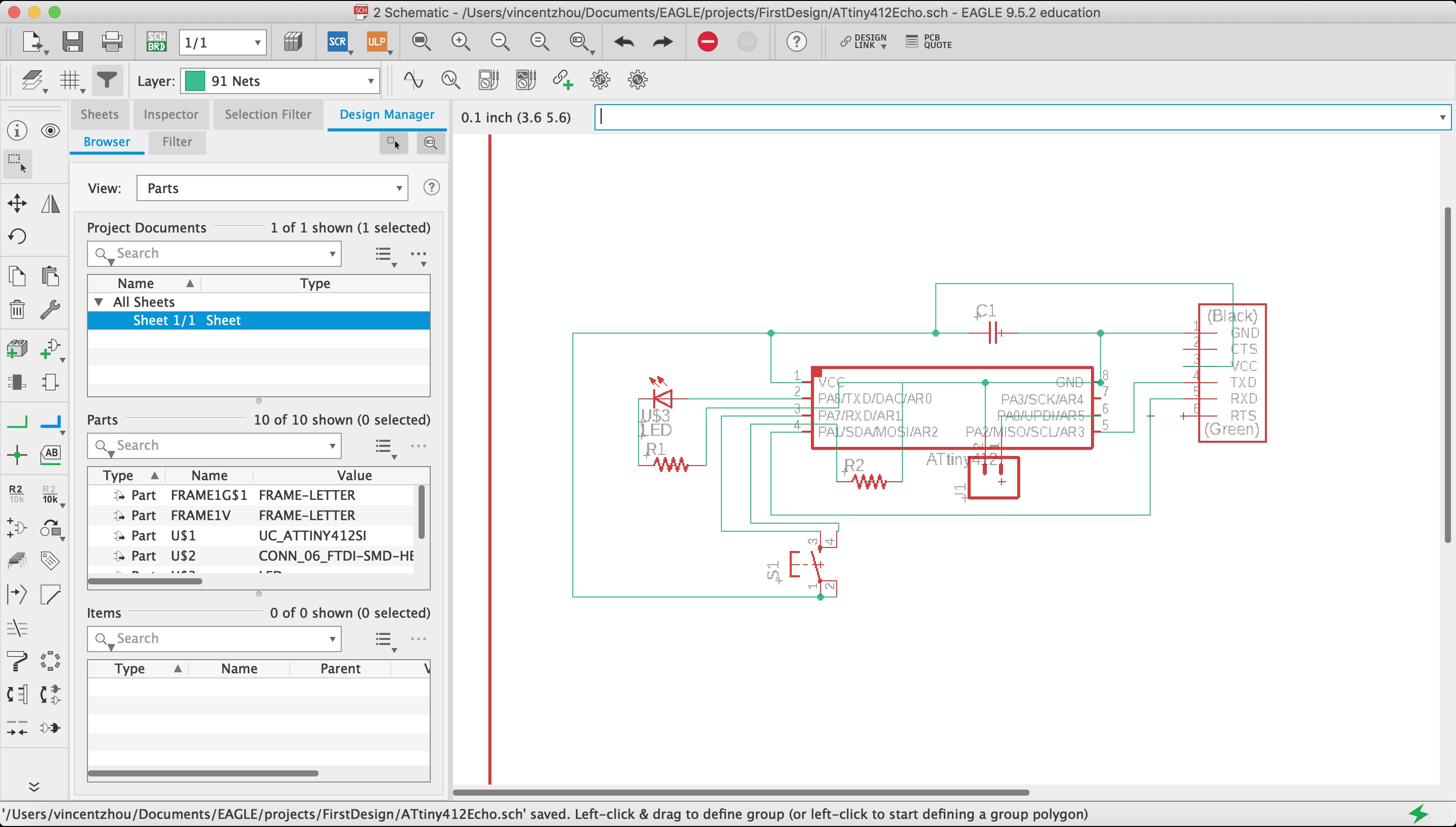
I created a new project in EAGLE and created a new Schematic in the project.
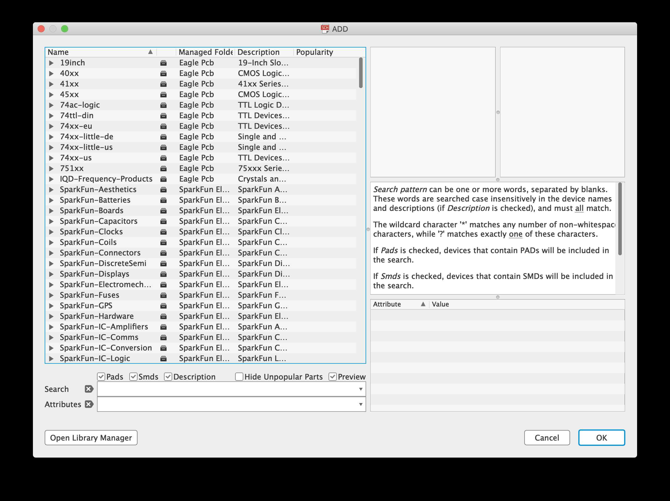
To add components, I clicked the add tool. This tool lists all the components that EAGLE has in its library.
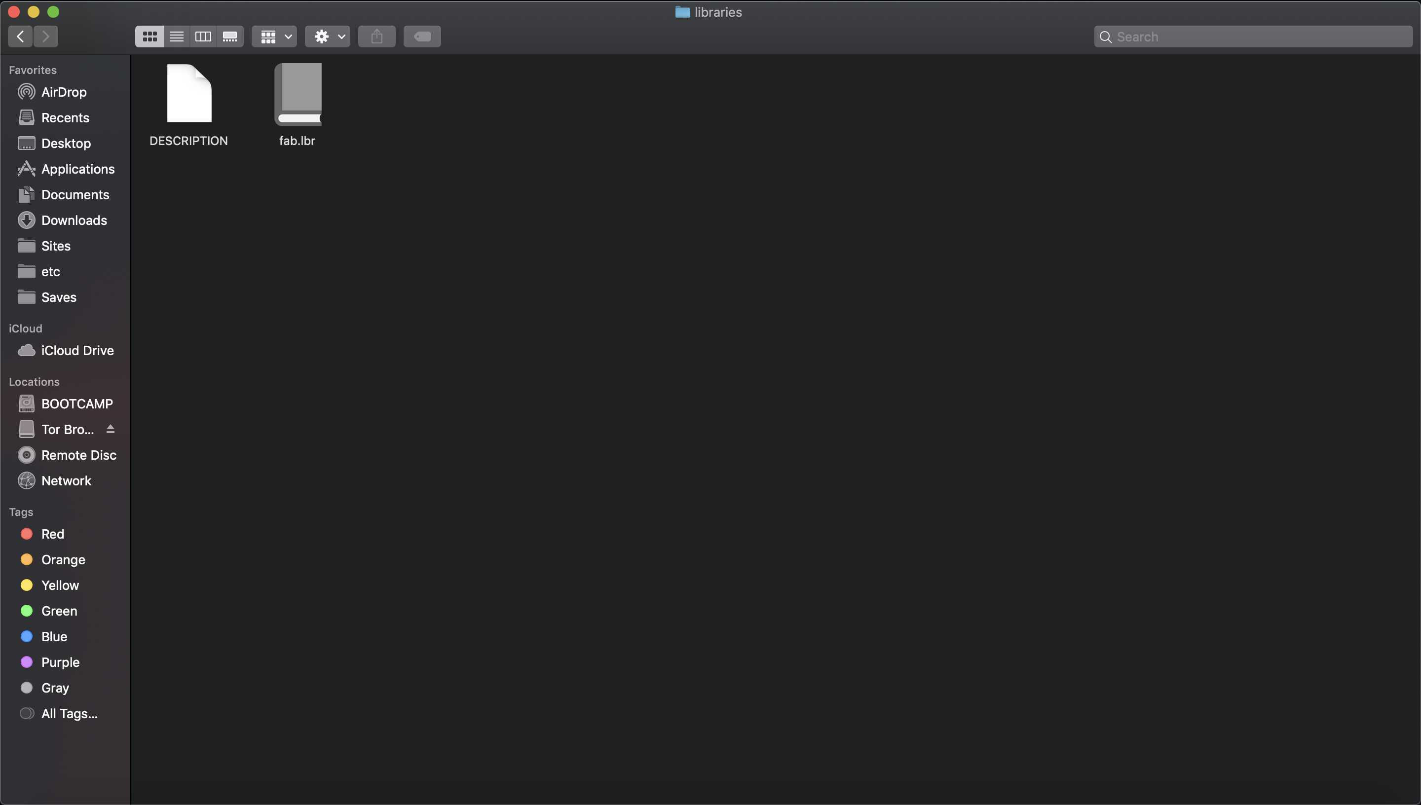
However, the library lacks Fab Academy specific components, such as the Attiny chips and UDPI and FTDI pin headers. The solution was to add the fab library into the libraries folder. Mr. Rudolph kindly provided a modified version of the fab library that included components for the new Attiny412 chips.
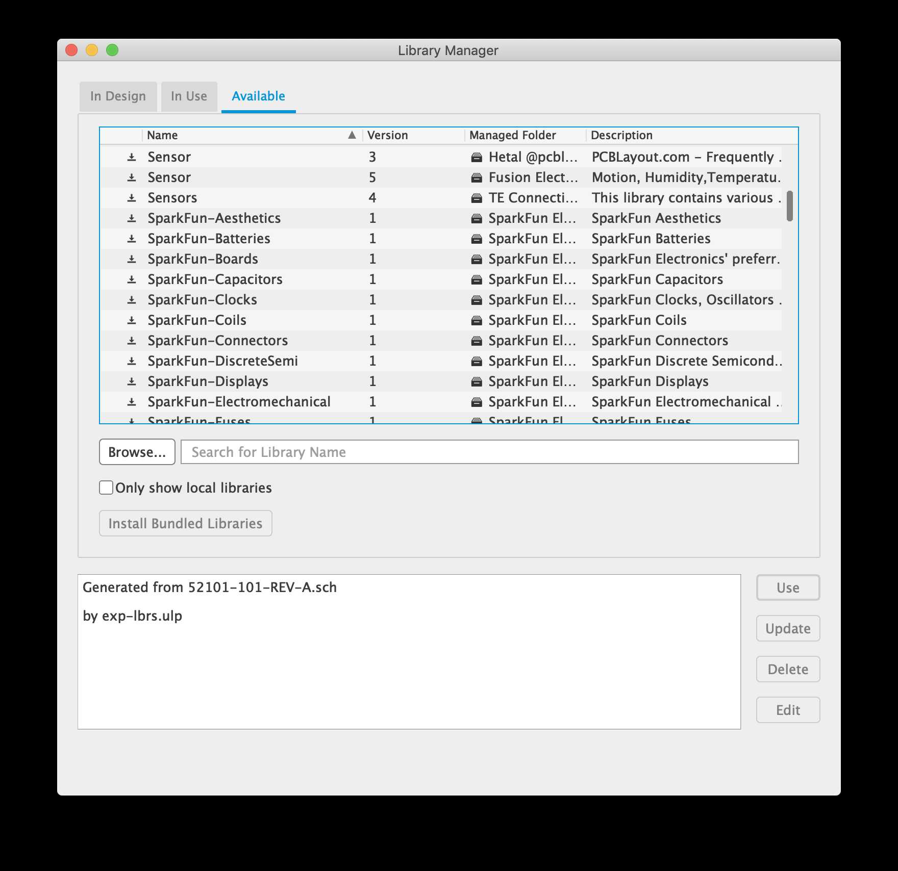
In addition to the Fab Library, I used the libarary manager to install all the SparkFun libraries.
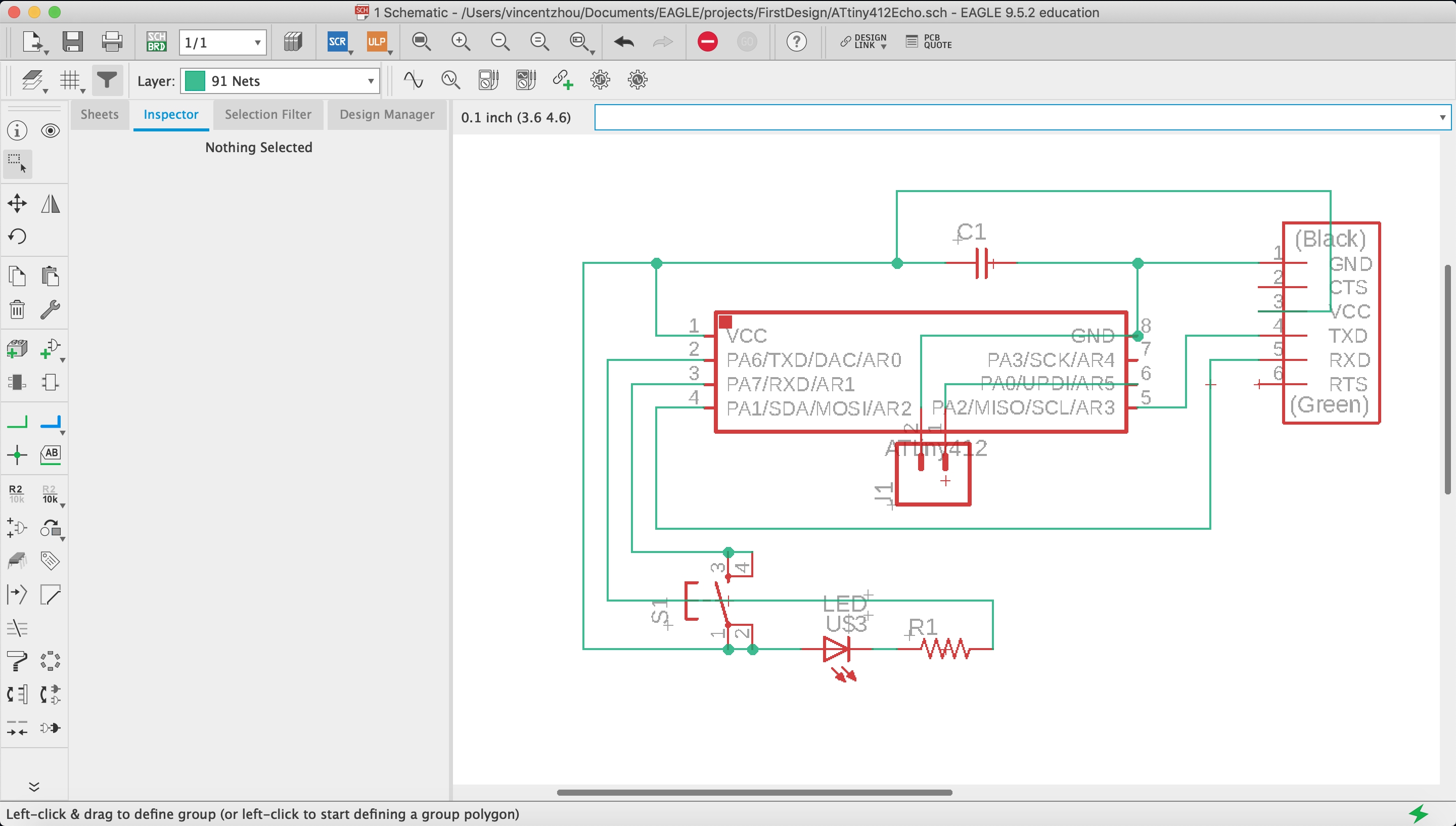
With all the prerequisites installed, I added all the components for the PCB and wired all the components up with the wire tool. I constantaly referenced Neil’s ATTiny412 schematics. Mr. Dubick recommended that I use the ATTiny412 chips, since it was more modern and easier to program.
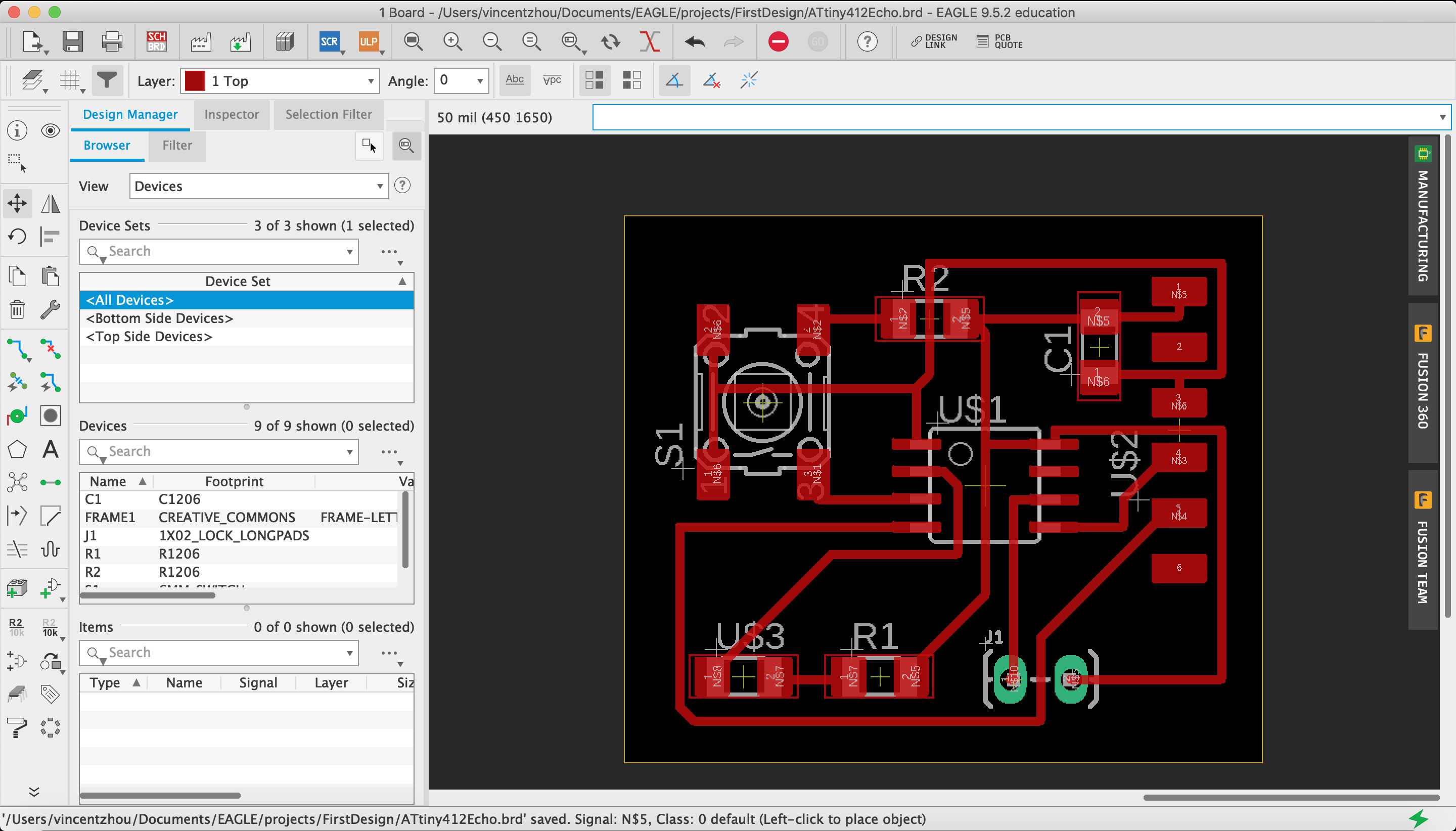
Next, I navigated to File > Switch to Board to generate the actual board layout.
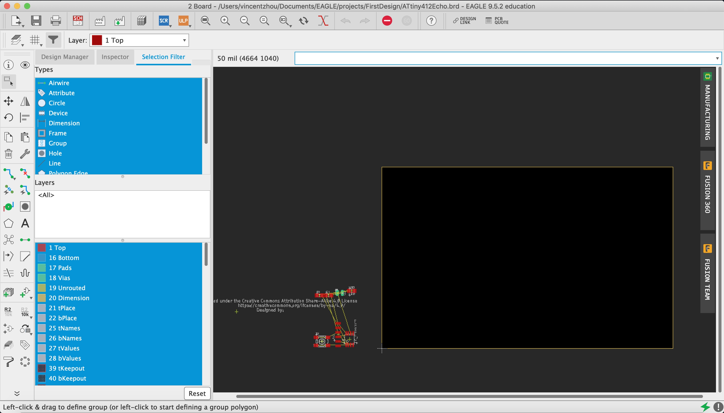
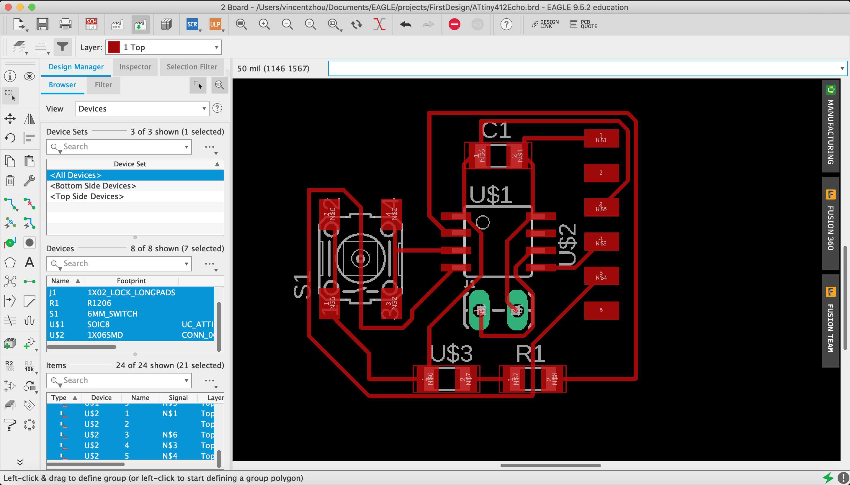
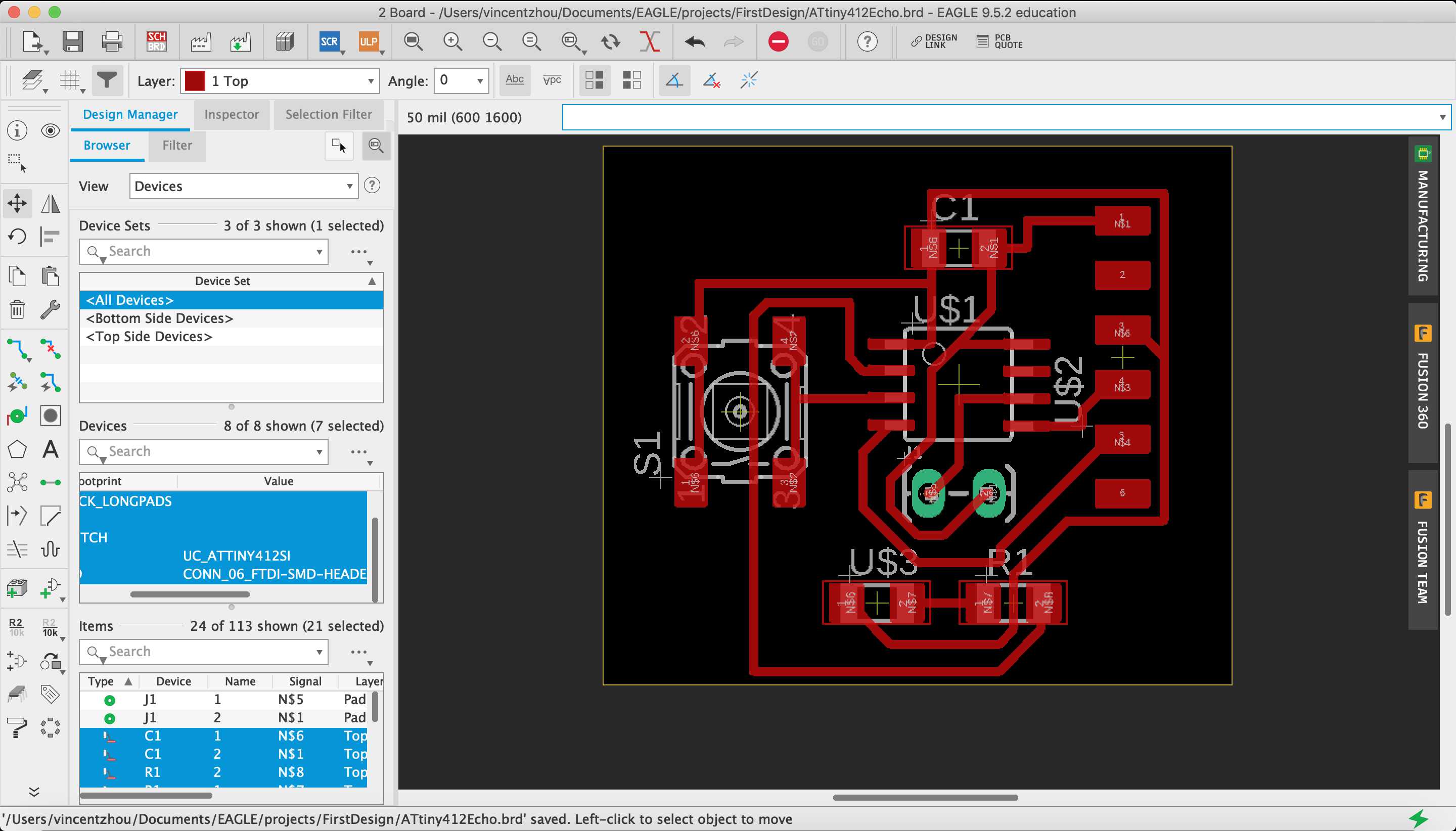
I moved the components into an orientation that I liked and used the autorouter tool to create the traces between the components.
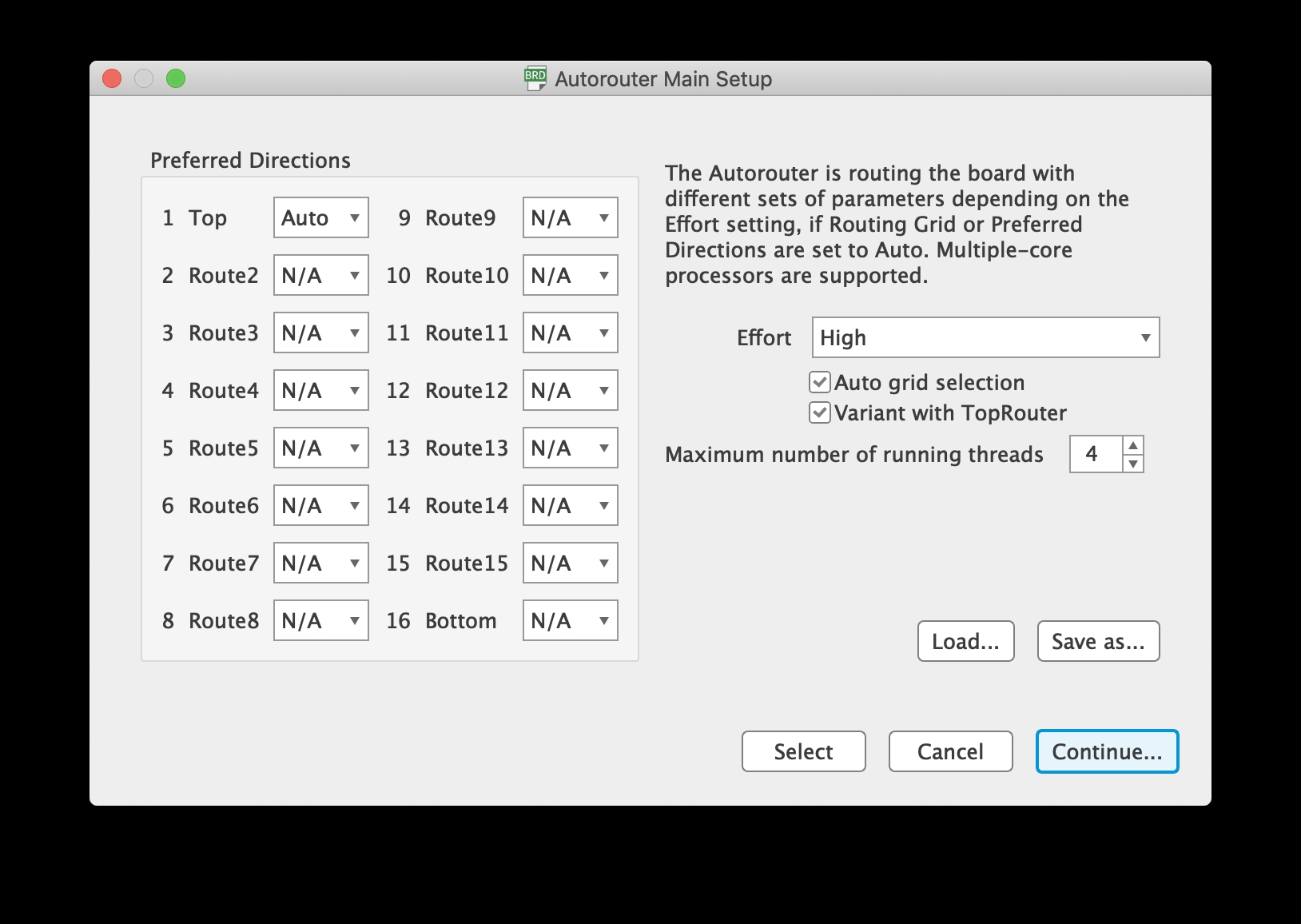
The autorouter produced multiple optimized paths that I could choose from. Here are two that I choose:
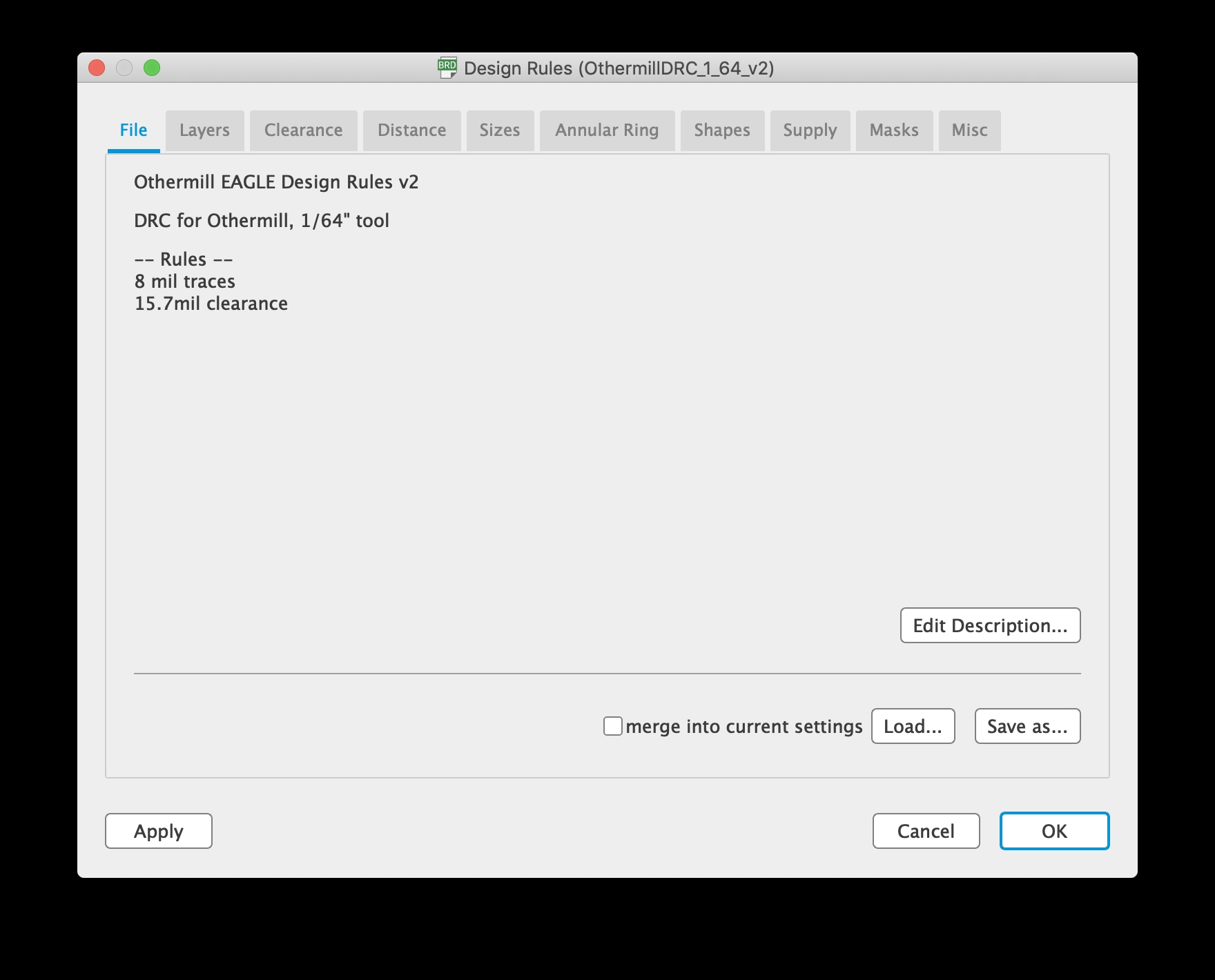
In addition, I had to incorporate design rules to make sure that the board would not run into issues while milling.
First, I mistakingly set the clearance to 12 mil when I thought that I was changing the size of the traces.
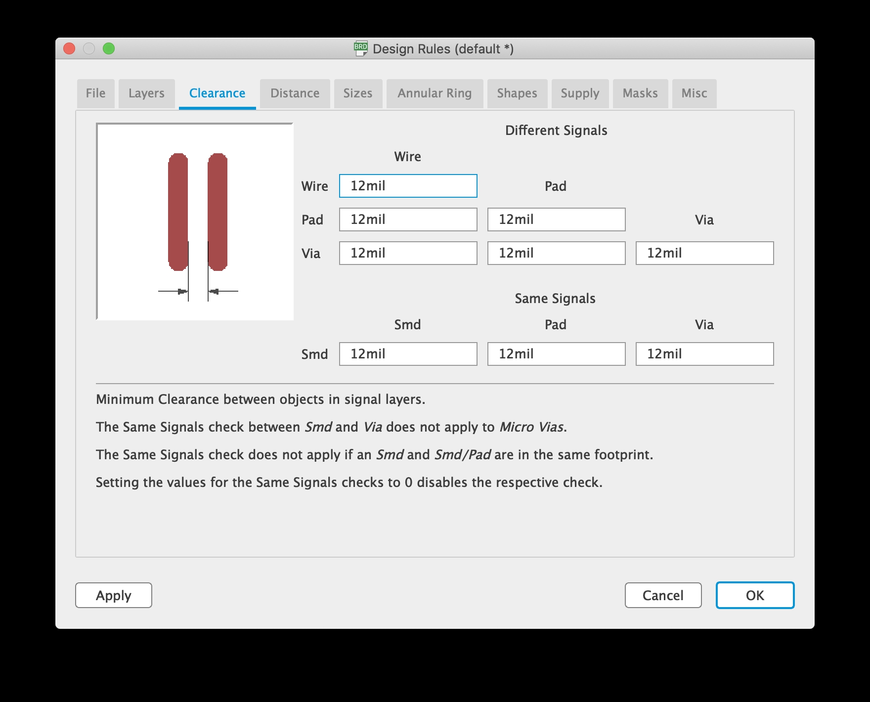
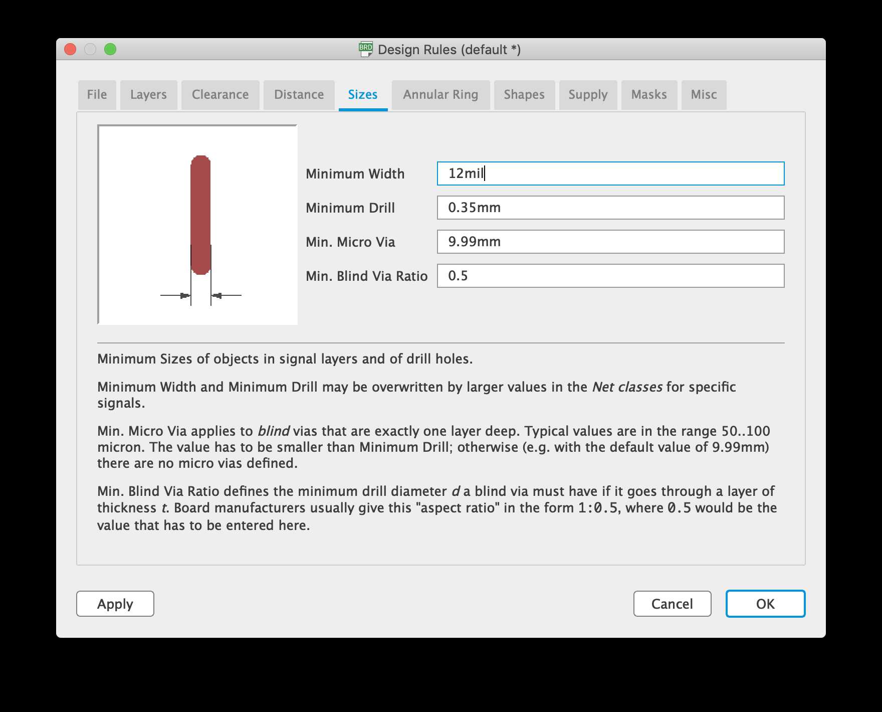
Then, I manually set the clearance to 6 mil and and trace size to 12 mil based on suggestion from Mr. Rudolph.
![]()
Thankfully, I googled the design rules for Bantam Tools and found out that Bantam Tools helpfully provides preconfigured design rule files for different bit sizes. I loaded the 1/64 in. file.
However, I began to realize that my schematic was wired the wrong way when I looked at Neil’s schematics. My LED was wired to VCC when it should be wired to ground. Also, Mr. Rudolph suggested adding a pull-down resistor to my button to ensure that the wire is digtial and not floating. I modified my schematic accordingly.
Since the board and schematic files are linked, the board reflected the changes. I ripped up the old traces, moved the new components into place, and used the autorouter to create new traces.
PCB Milling
Another helpful feature of Bantam Tools that I found out is the fact that the software can directly accept .brd files. This means that I do not need to go through the process of vectorizing with Fab Mods.
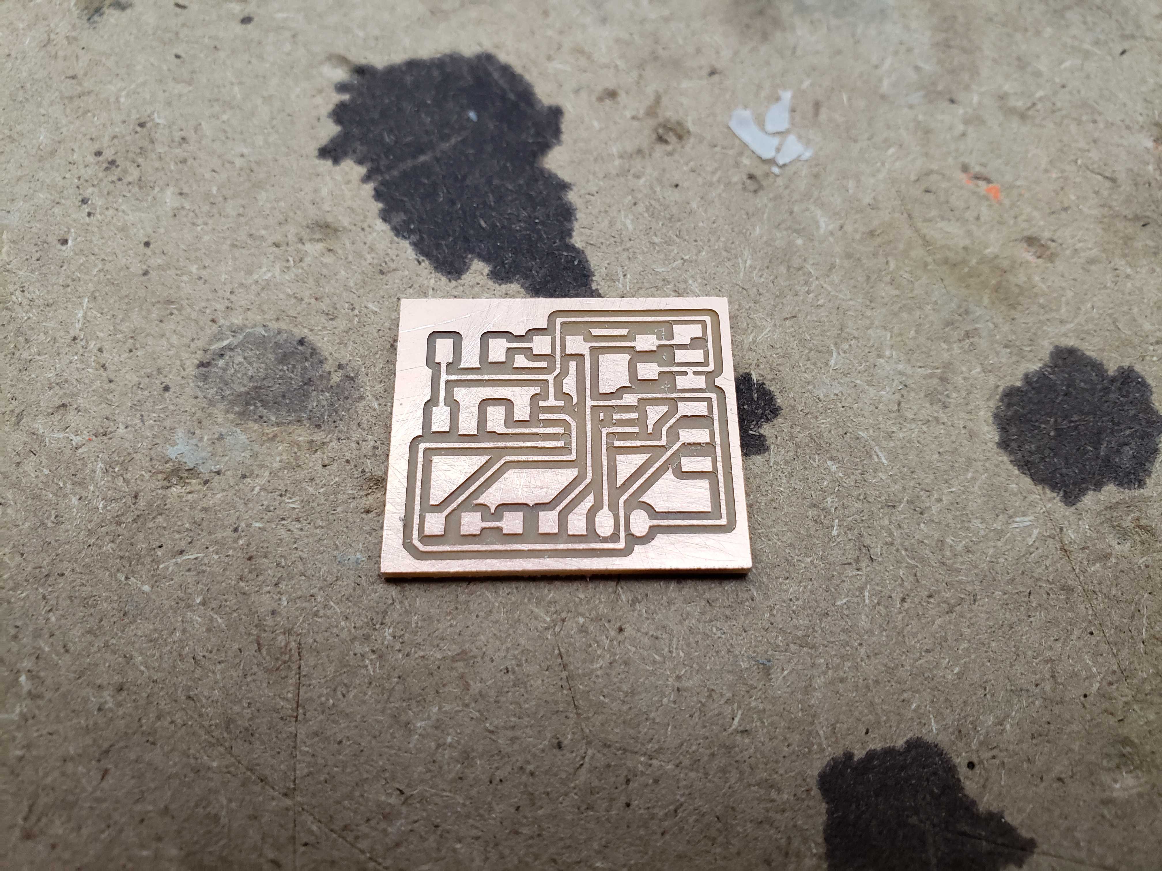
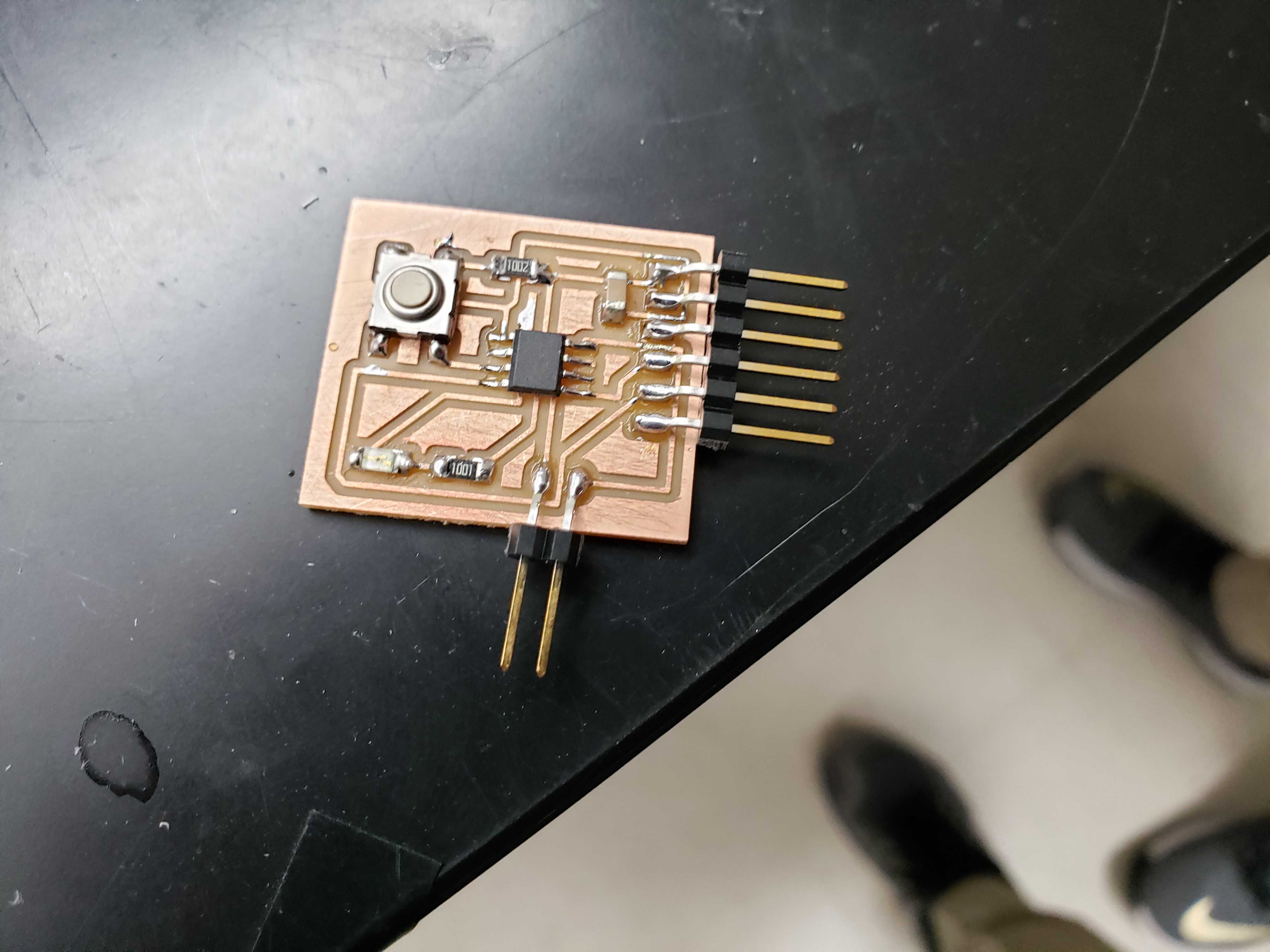
I milled and soldered the first board before I realized that the schematic was wrong.
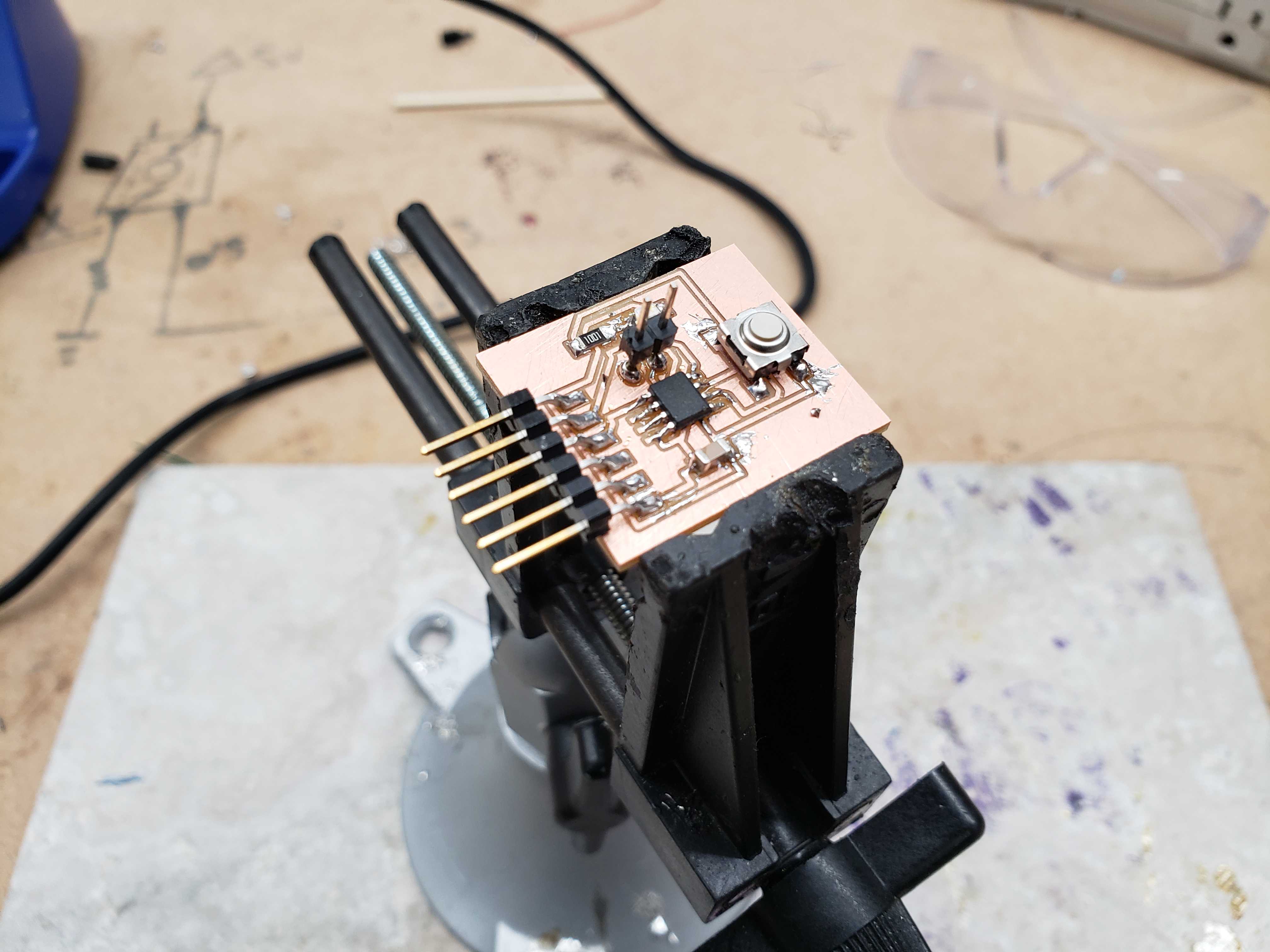
Then, I made another board with the updated schematic.
Programming
The ATTiny412 requires a UDPI programmer, making it different than the chips used by previous Fab Academy alumni.
We programmed the ATTiny412 using this guide.
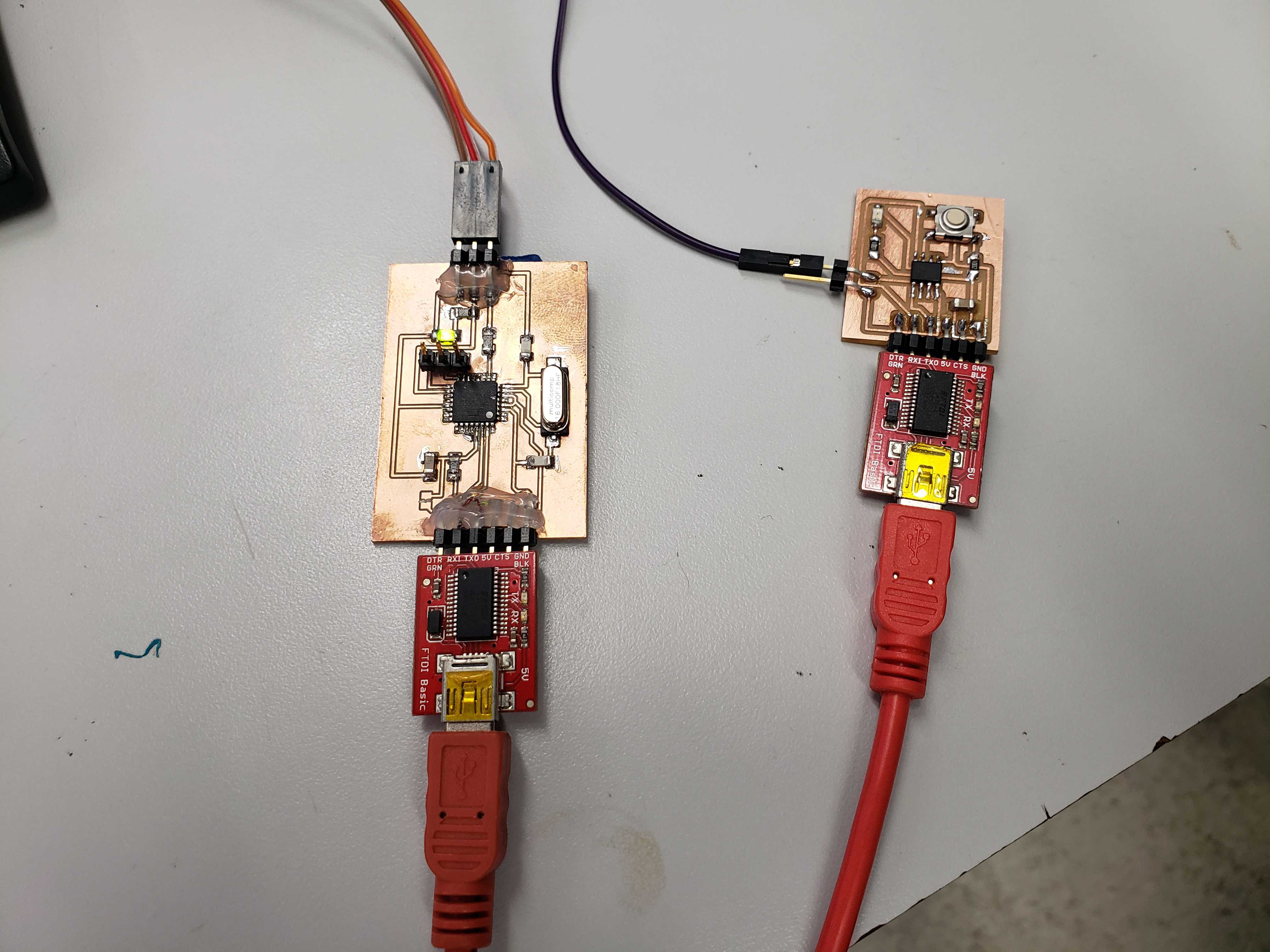
Mr. Rudolph had already produced UDPI programmers, so we used his programmer. We made sure that the UDPI pins, VCC pins, and ground pins were connected together correctly.
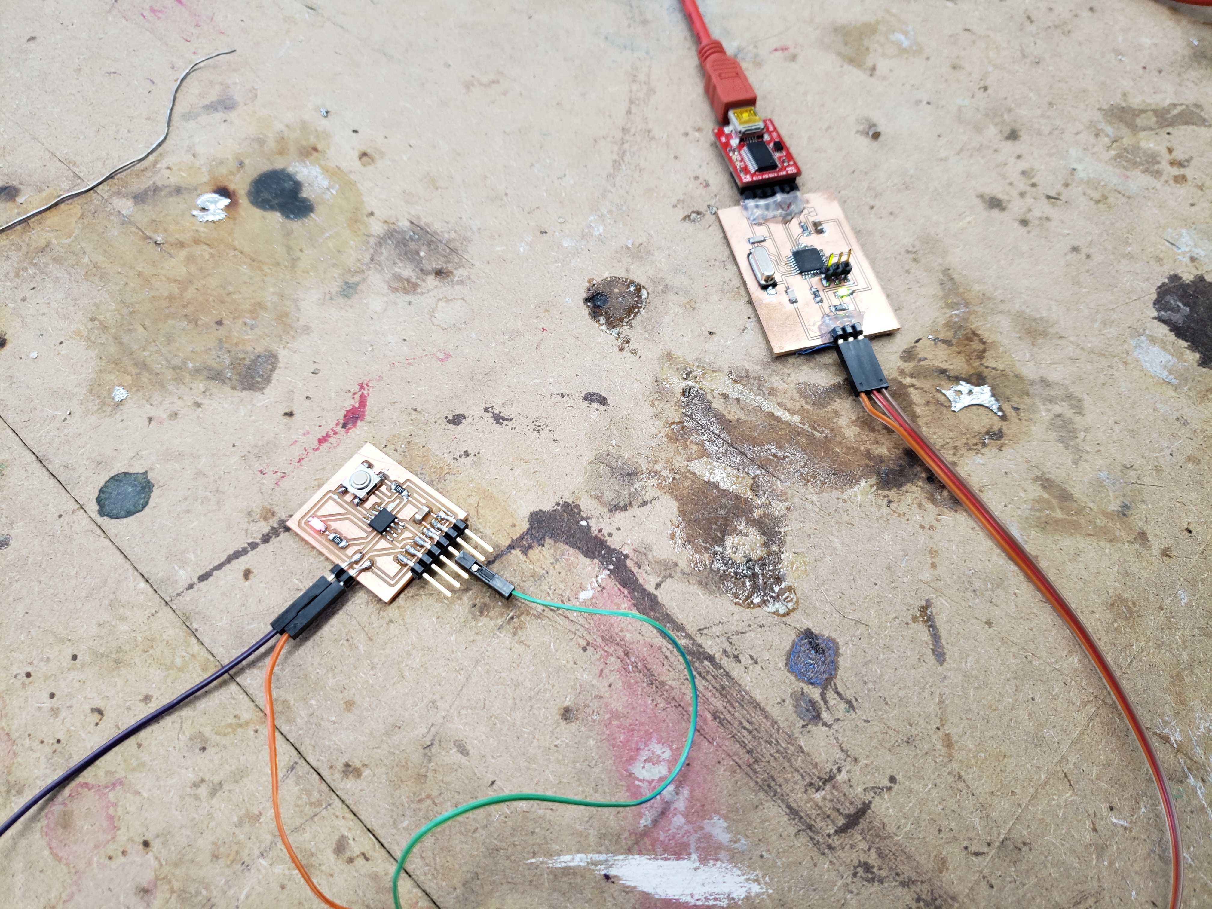
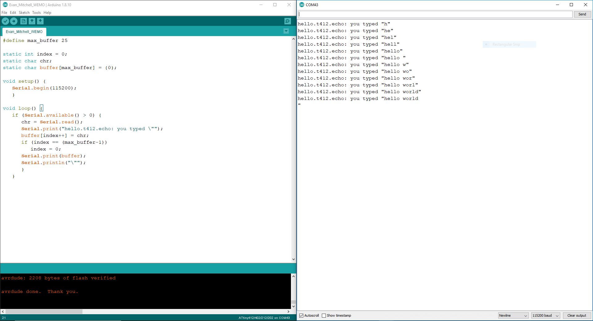
I uploaded Neil’s echo code onto the board and typed messages in the serial monitor to see if the echo worked. As expected, I received the message back.
I also tried Mr. Rudolph’s button-LED code, however, I found out that something in my circuit is inverted because the LED turns off when I press the button. Looking at the schematic, I figured that the most likely reason was the ground and VCC on the button was inverted, causing the pull-down resistor to become a pull-up resistor.
Update
It turns out that Mr. Rudolph’s code is actually inverted. The pull-down resistor is actualy functional. I found out during Week 9 when I was programming my chip and the digitalRead() function reflected the state of the button. It seems that I overlooked the internal pull-up resistor that Mr. Rudolph set in the setup() function.