9. Embedded programming
In this week the purpose of the assignment was to
-
Read a microcontroller data sheet
-
Program my board to do something, with as many different programming language and programming environments as possible
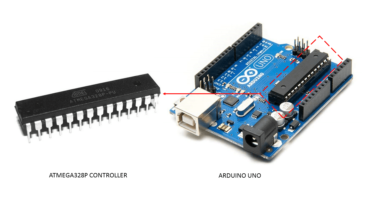
In my case I’ll have to do this assignment slightly different as a start since I couldn’t have access in the lab since week 6. So I wont be using my own Attiny 1614 board that I designed. Instead I’ll be using Arduino Uno ATmega328 controller with a breadboard.
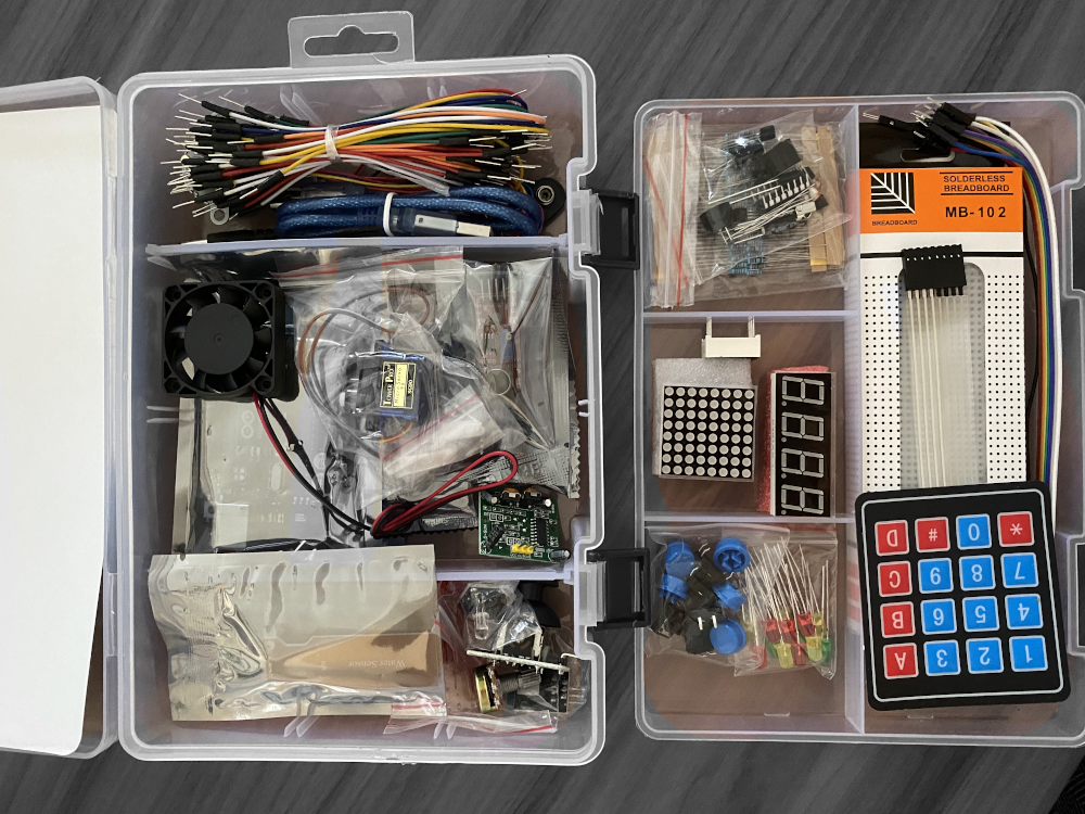
To proceed with the coursework for this week, I ordered an Arduino kit online and it got delivered to me at the same day and I was ready to go :)
Programming Environment
There are many programming environments to program. Atmel Studio and Arduino IDE is the most common.
As a starting point, I downloaded Arduino IDE from here
Datasheets and Summary
A datasheet is a document that tells you everything about the microcontroller. These specifications provide adequate information about the function of each pin and other important information for example, how much voltage you want to give it? The information provided by a datasheet become handy when designing and programming a circuit.
In my case, the microcontroller I used is ATmega328p. A complete datasheet is found here. And for a summary click here
“Reading a datasheet may seem overwhelming but understanding how you look for information in a datasheet is key. You don’t have to read the full document to be able to use the microcontroller!”
Getting Started with Arduino IDE
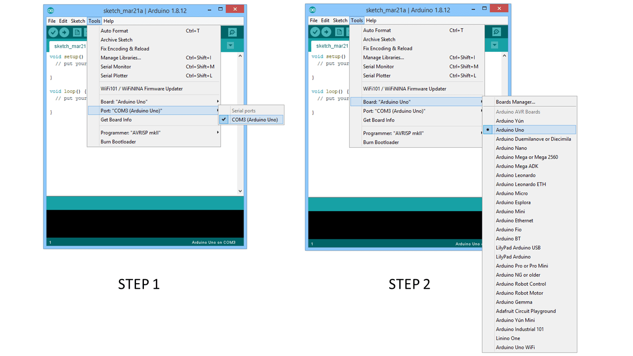
After installing the software, I connected my arduino uno to the computer using a usb cable. I then had to identify my board to the software by following two simple steps as shown below.
Running a Blink Program
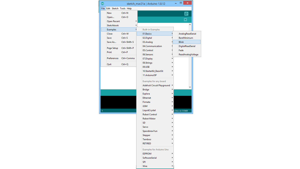
A blink is the simplest form of program to start with after connecting the arduino uno to the computer.
To do so I followed the steps as shown in the picture below.
- Reading the Code
Below is a general explanation of the main lines used in this code
Here is the result, I also tried to increase the seconds in between the blinks as shown in the second video below.
Breadboard and Components
Breadboard
Before starting with setting up the circuit and programming it, a quick introduction to how the breadboard works was important, specially that it was my first time using one !
What is a breadboard?
A breadboard is plastic rectangular object with holes which enable electrical connections without using solder or melted metal to bond electronics component together. That’s why it’s referred to as solderless breadboards.
The following diagram explains the basic notes you need to know before using a breadboard.

Components
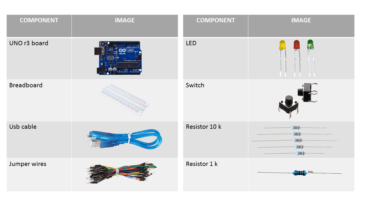
The Arduino kit included a lot of components, I will list down the components I used for the following exercise.
Switch Control Programming
I then tried to control the LED that is already on the Arduino uno board by adding a switch button and programming it to do so.
- Making the connections:
Based on some research I connected my components on the breadboard to the Arduino uno as shown below.

- The Code
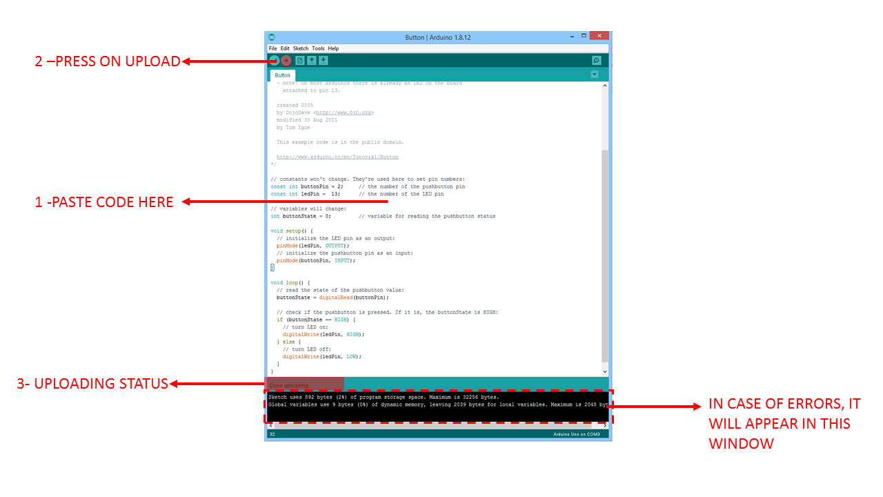
At the beginning, I copied a code from a tutorial I followed. I pasted it in a new file and then clicked on upload
// constants won't change. They're used here to set pin numbers:
const int buttonPin = 2;     // the number of the pushbutton pin
const int ledPin =  13;      // the number of the LED pin

// variables will change:
int buttonState = 0;         // variable for reading the pushbutton status

void setup() {
  // initialize the LED pin as an output:
  pinMode(ledPin, OUTPUT);
  // initialize the pushbutton pin as an input:
  pinMode(buttonPin, INPUT);
}

void loop() {
  // read the state of the pushbutton value:
  buttonState = digitalRead(buttonPin);

  // check if the pushbutton is pressed. If it is, the buttonState is HIGH:
  if (buttonState == HIGH) {
    // turn LED on:
    digitalWrite(ledPin, HIGH);
  } else {
    // turn LED off:
    digitalWrite(ledPin, LOW);
  }
}
- Testing the button I then pressed on the button and it worked !!
Adding An external LED and Button
I wanted to also add another button and an external LED to my breadboard. So I added the same components as the previous exercise in addition to an LED and a resistor of 1K ohm.
I then connected the components as shown below
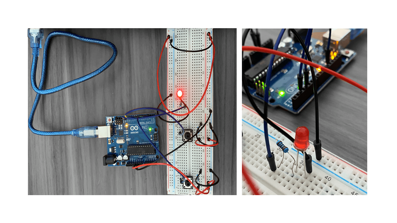
I uploaded a new code of the second button and allocated the new pins values. And here is the result.
Key Takeaways
While working on this part I learnt a couple of things
-
In this type of LED (the breaboard LED), the way we can determine the cathode(-) and Anode(+) is by looking at the length of the pins. The longer pin is the Anode, and the shorter is the Cathode.
-
The Anode pin is what we connect to the resistor and the Cathode to the ground
-
We can know the value of resistor using an online color coded calculator by entering the colors of the line on the resistor we are using as shown Below
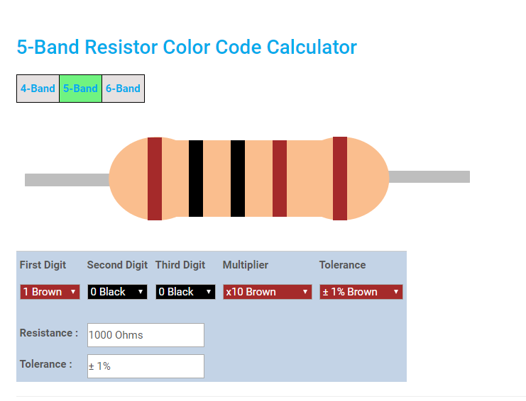
You can find this calculator here
Problems Faced
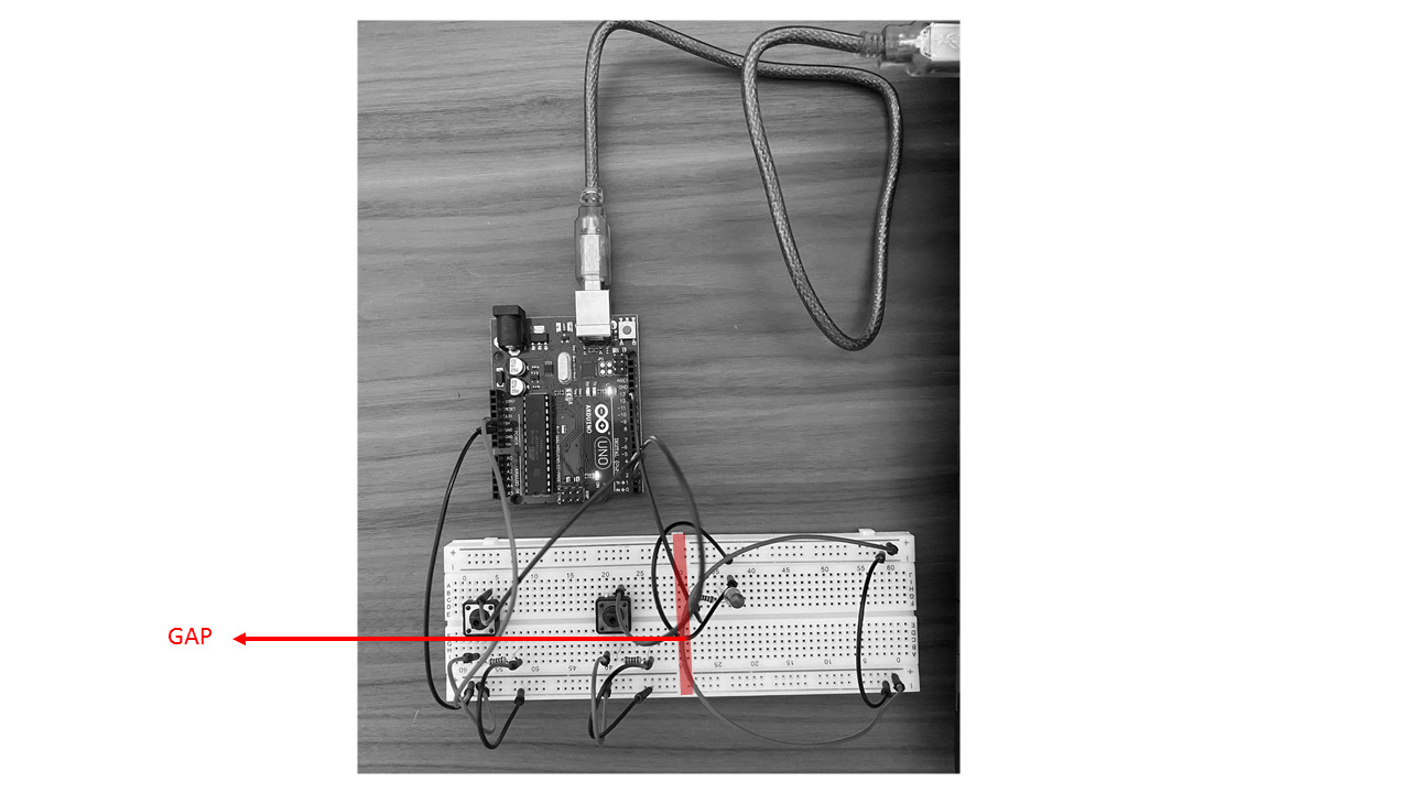
1- Gap in Ground Connection
After connecting everything and made sure everything is connected in the right way. The program was uploaded succefully without any errors. However, the LED didn’t let. I made sure my jumpers are fixed and I also doubled check where my pins are connected to and checked the led cathode and anode connections. Everything looked ok but the LED still isn’t lighting. I tried also to reduce the resistor value from 1K to 220 ohm but this also didn’t solve the problem.
I then decided to try connecting the led to the vcc pin directly hoping that light will go on. But this didn’t work as well. So I finally connected the Led ground directly to the arduino and only then the light turned on !!!
I then knew that my problem was in the ground connection. And that was due to the gap that some larger breadboards may have in between the holes which disconnected the elements as shown in the image below
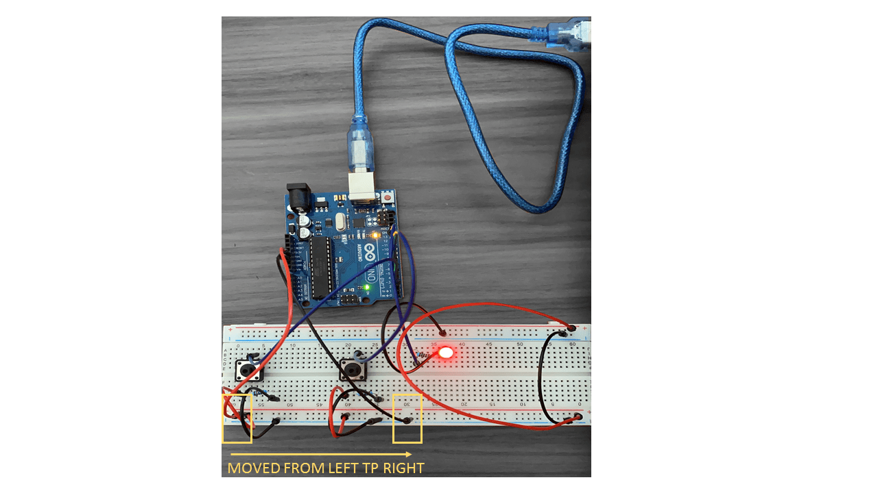
Solution :
So to solve this problem, I moved the jumper location on the breadboard to be below the led as show in the picture
2- LED wont go off when controlling it with the button