Final Project
Post
Video
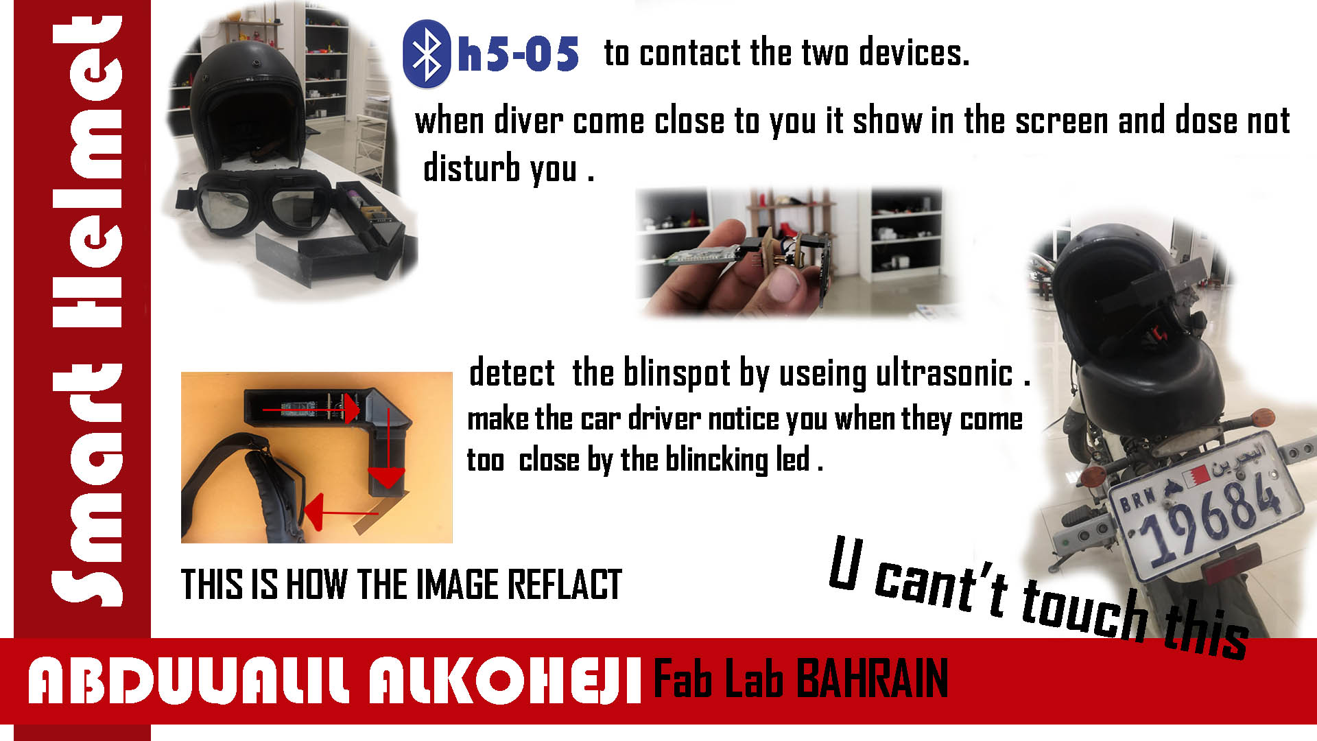
Smart Helmet
safety is the first thing everybody thinks about when they ride a motorcycle for the first time when you drive it you must always be faced on the road and be careful to what is around you, sometimes you are careful but the people around you are not and this what make motorcycle scary. and one day I saw an accident in front of me, and this accident make me think about how to make the ridding motorcycle more safe.
My Project is to make ridding motorcycle safer by making the helmet give you a notification when every car is in the blind spot or to close to the rider. This will make them know what happened around of them, and that how my project make the ridding more safe.
How it work
the Project contain of two devises one of them is attach to helmet and the other on the motorcycle.
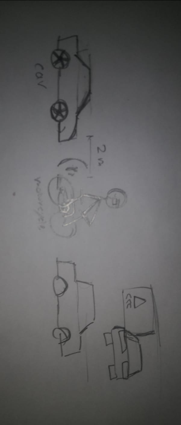
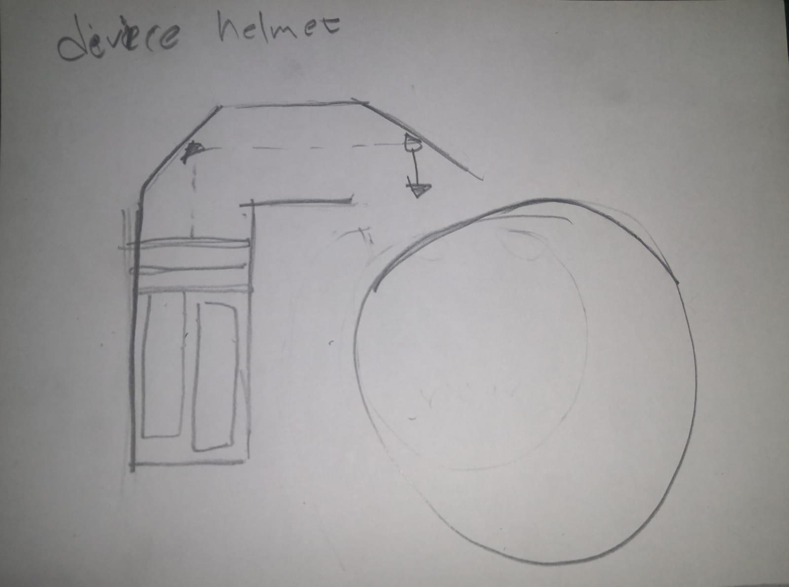
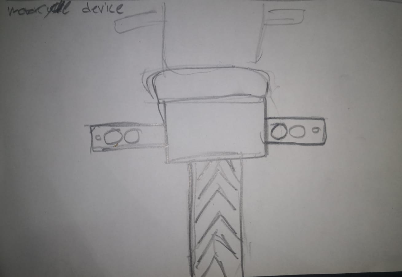
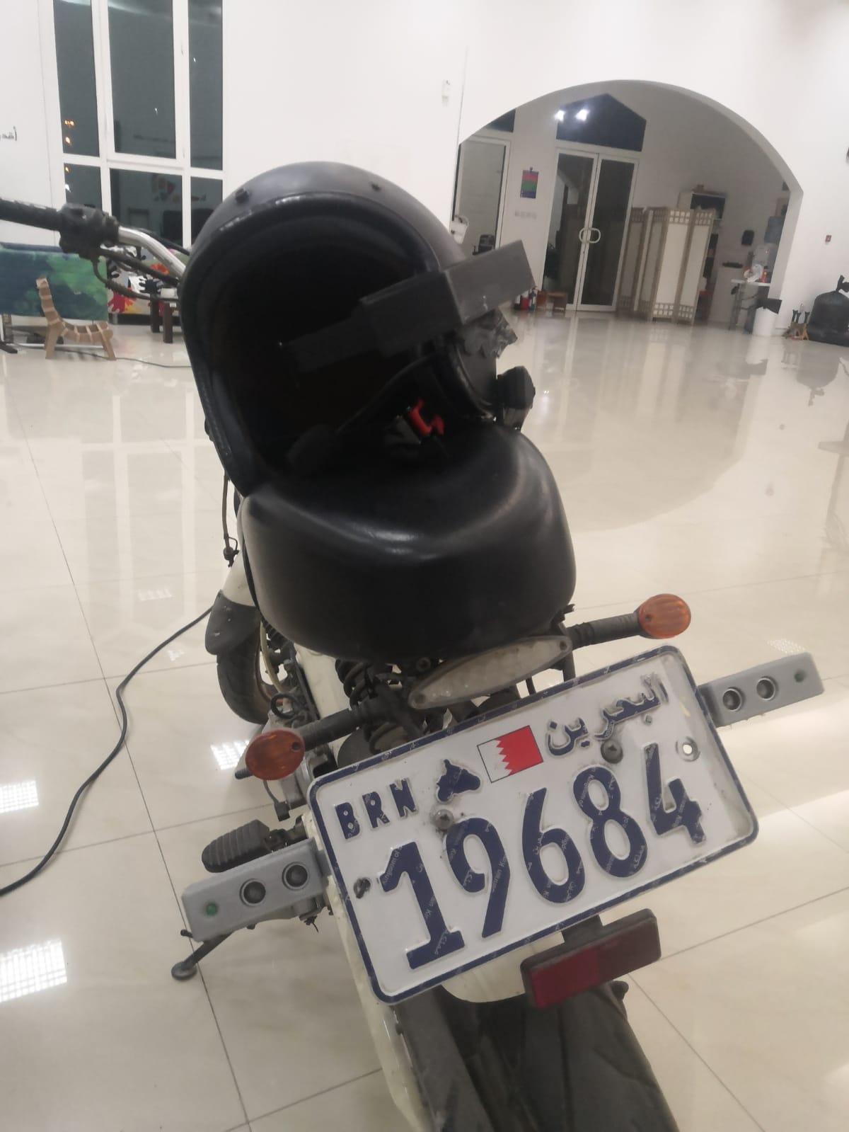
the device in the motorcycle will have two ultrasonic sensor at each side at the back in the plate number of the motorcycle too cover more space behind the rider and if it since any thing in three meter and make light blink near the sensor, and at the same time it send data by Bluetooth to the other device that there is something behind you and this device that attach to the helmet have screen and this screen will show dingers sign without making the rider by making the screen reflect on transparent plastic on front of the rider eye. and the dingers sign will appear at the same side that someone close behind you.
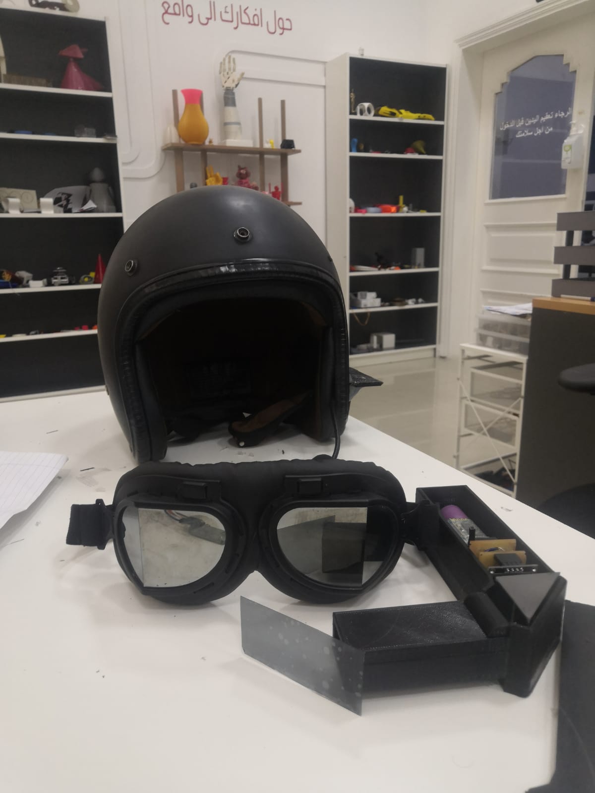
the way that the rider will know if someone close form the back without disturbing the rider, so I did a small hologram the screen will show the dingers sign then it will reflect on prim and it will reflect it 90 degree after that I put 45 degree transferee plastic in front of the rider, so when there are something close to the rider from the back the screen will work and even if it dose it will not block.
steps
- design sketch how the project will work.
- design electronic.
- coding.
- Prototype for helmet device.
- 2D and 3D molding.
Electronics
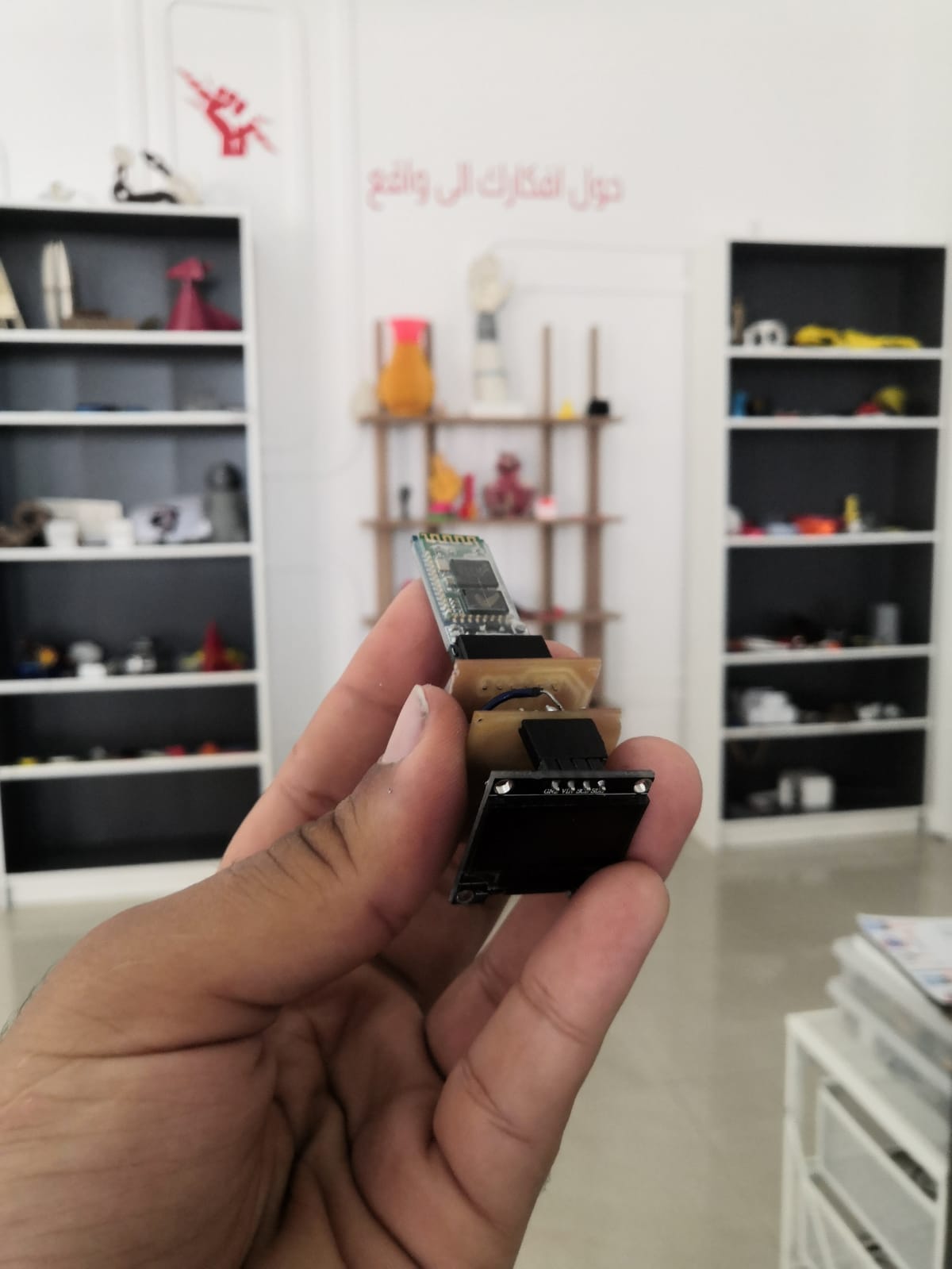
helmet device
you can find more information about it in the output device week here
the sandwich circuit it is three layer in front of each other, the first thing screen next to it is the microcontroller and some main component the last layer is circuit to contacted to the Bluetooth and power, this way of board help me to fit it all in small case.
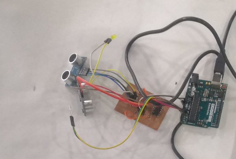
Motorcycle device
you can find more information about it in the input device week here
I did the circuit to detect what is near the rider from the back by two sensor one at each side near to the sensor and give notification for the rider other people in the road that they are close to the rider by blinking light work when ever they are in rang of 3 meter.
Network
I used Bluetooth HC-05 Module in both of devices to transfer the data between then and it is harder than I think about it, but at the end I did it.
for more information about what use and how did I pear the two devices together and way I used this type of network and more you can find it in the Networking and communications week here
Code
helmet device
in the output week I explain how the code work in the code section here
 // the setup function runs once when you press reset or power the board
 void setup() {
   // initialize digital pin LED_BUILTIN as an output.
   pinMode(LED_BUILTIN, OUTPUT);
 }

 // the loop function runs over and over again forever
 void loop() {
   digitalWrite(LED_BUILTIN, HIGH);   // turn the LED on (HIGH is the voltage level)
   delay(1000);                       // wait for a second
   digitalWrite(LED_BUILTIN, LOW);    // turn the LED off by making the voltage LOW
   delay(1000);                       // wait for a second
 }#include <Tiny4kOLED.h>
 #include "SolomonSystech.h"
 #include <SoftwareSerial.h>
 SoftwareSerial mySerial(1,6); // RX1, TX6
 // ============================================================================

 void setup() {


   oled.begin();
   oled.clear();
   oled.bitmap(0,0, 128,4, logo);
   oled.on();
   delay(1000);
   oled.clear();

  mySerial.begin(9600);
 }

 void loop() {
   int x = 0 ;
  if(mySerial.available() > 0){
     x = mySerial.read();
  }

  if (x == '1')
  {
   oled.begin();
   oled.clear();
   oled.bitmap(0,0, 128,4, lift1);
   oled.on();
   delay(250);

   oled.begin();
   oled.clear();
   oled.bitmap(0,0, 128,4, lift2);
   oled.on();
   delay(250);

   oled.begin();
   oled.clear();
   oled.bitmap(0,0, 128,4, lift3);
   oled.on();
   delay(250);
  }

   if (x == '2')
   {
   oled.begin();
   oled.clear();
   oled.bitmap(0,0, 128,4, right1);
   oled.on();
   delay(250);


   oled.begin();
   oled.clear();
   oled.bitmap(0,0, 128,4, right2);
   oled.on();
   delay(250);

   oled.begin();
   oled.clear();
   oled.bitmap(0,0, 128,4, right3);
   oled.on();
   delay(250);
   }
   else {
   oled.begin();
   oled.clear();

   }
   }
convert the photo to code

I used website to help me do this
this web convert the image to code then the so the read the code and convert it to image into the screen.
the photo code
 const uint8_t logo [] PROGMEM = {
   0x00, 0x00, 0x00, 0x00, 0x00, 0x00, 0x00, 0x00, 0x00, 0x00, 0x00, 0x00, 0x00, 0x00, 0x00, 0x00,
   0x00, 0x00, 0x00, 0x00, 0x00, 0x00, 0x00, 0x00, 0x00, 0x00, 0x00, 0x00, 0x00, 0x00, 0x00, 0x00,
   0x00, 0x00, 0x00, 0x00, 0x00, 0x38, 0x00, 0x00, 0x20, 0x18, 0x18, 0x10, 0x00, 0x38, 0x00, 0x08,
   0x18, 0x10, 0x20, 0x00, 0x00, 0x30, 0x18, 0x18, 0x30, 0x00, 0x38, 0x00, 0x38, 0x00, 0x00, 0x00,
   0x38, 0x00, 0x00, 0x38, 0x00, 0x10, 0x18, 0x18, 0x20, 0x38, 0x00, 0x00, 0x18, 0x00, 0x38, 0x10,
   0x10, 0x28, 0x20, 0x18, 0x18, 0x18, 0x20, 0x00, 0x38, 0x00, 0x38, 0x08, 0x10, 0x38, 0x00, 0x00,
   0x00, 0x00, 0x00, 0x00, 0x00, 0x00, 0x00, 0x00, 0x00, 0x00, 0x00, 0x00, 0x00, 0x00, 0x00, 0x00,
   0x00, 0x00, 0x00, 0x00, 0x00, 0x00, 0x00, 0x00, 0x00, 0x00, 0x00, 0x00, 0x00, 0x00, 0x00, 0x00,
   0x00, 0x00, 0x00, 0x00, 0x00, 0x00, 0x00, 0x00, 0x00, 0x00, 0x00, 0x00, 0x00, 0x00, 0x00, 0x00,
   0x00, 0x00, 0x00, 0x00, 0x00, 0x00, 0x00, 0x00, 0x00, 0x00, 0x00, 0x00, 0x00, 0x00, 0x00, 0x00,
   0x00, 0x00, 0x00, 0x00, 0x00, 0x00, 0x00, 0x00, 0x00, 0x00, 0x00, 0x00, 0x00, 0x00, 0x00, 0x00,
   0x00, 0x00, 0x00, 0x00, 0x00, 0x00, 0x00, 0x00, 0x00, 0x00, 0x00, 0x00, 0x00, 0x00, 0x00, 0x00,
   0x00, 0x00, 0x00, 0x00, 0x00, 0x00, 0x00, 0x00, 0x00, 0x00, 0x00, 0x00, 0x00, 0x00, 0x00, 0x00,
   0x00, 0x00, 0x00, 0x00, 0x00, 0x00, 0x00, 0x00, 0x00, 0x00, 0x00, 0x00, 0x00, 0x00, 0x00, 0x00,
   0x00, 0x00, 0x00, 0x00, 0x00, 0x00, 0x00, 0x00, 0x00, 0x00, 0x00, 0x00, 0x00, 0x00, 0x00, 0x00,
   0x00, 0x00, 0x00, 0x00, 0x00, 0x00, 0x00, 0x00, 0x00, 0x00, 0x00, 0x00, 0x00, 0x00, 0x00, 0x00,
   0x00, 0x00, 0x00, 0x00, 0x00, 0x00, 0x00, 0x00, 0x00, 0x00, 0x00, 0x00, 0x00, 0xfe, 0xfe, 0xc0,
   0xe0, 0xf0, 0xb0, 0x18, 0x0c, 0x06, 0x02, 0x00, 0x00, 0xf8, 0xfc, 0x0c, 0x06, 0x06, 0x02, 0x02,
   0x06, 0x06, 0x0c, 0xfc, 0xf0, 0x00, 0x00, 0xe0, 0xf8, 0x1c, 0x04, 0x06, 0x02, 0x02, 0x02, 0x06,
   0x06, 0x1c, 0xf8, 0xf0, 0x00, 0x00, 0x00, 0xfe, 0xfc, 0x40, 0x40, 0x40, 0x40, 0x40, 0x40, 0xfe,
   0xfe, 0x00, 0x00, 0x00, 0x00, 0xfe, 0xfe, 0x46, 0x46, 0x46, 0x46, 0x46, 0x46, 0x42, 0x00, 0x00,
   0x00, 0x06, 0x06, 0x06, 0xfe, 0xfc, 0x00, 0x00, 0x02, 0x06, 0xfe, 0xfe, 0x06, 0x02, 0x00, 0x00,
   0x78, 0xfc, 0xc6, 0x86, 0x82, 0x82, 0x86, 0xdc, 0xf8, 0x60, 0x00, 0x10, 0x7c, 0xfc, 0x86, 0x82,
   0x82, 0x86, 0x86, 0xfc, 0xf8, 0x00, 0x00, 0x00, 0x00, 0x00, 0x00, 0x00, 0x00, 0x00, 0x00, 0x00,
   0x00, 0x00, 0x00, 0x00, 0x00, 0x00, 0x00, 0x00, 0x00, 0x00, 0x00, 0x00, 0x00, 0x1f, 0x0f, 0x00,
   0x00, 0x01, 0x03, 0x07, 0x0e, 0x0c, 0x18, 0x00, 0x00, 0x03, 0x07, 0x0c, 0x08, 0x18, 0x18, 0x18,
   0x18, 0x08, 0x0c, 0x07, 0x03, 0x00, 0x00, 0x01, 0x07, 0x0f, 0x0c, 0x18, 0x18, 0x18, 0x18, 0x18,
   0x0c, 0x0e, 0x07, 0x01, 0x00, 0x00, 0x00, 0x1f, 0x0f, 0x00, 0x00, 0x00, 0x00, 0x00, 0x00, 0x0f,
   0x1f, 0x00, 0x00, 0x00, 0x00, 0x1f, 0x1f, 0x18, 0x18, 0x18, 0x18, 0x18, 0x18, 0x08, 0x00, 0x18,
   0x18, 0x18, 0x18, 0x0c, 0x0f, 0x03, 0x00, 0x00, 0x08, 0x18, 0x1f, 0x1f, 0x18, 0x08, 0x00, 0x00,
   0x00, 0x18, 0x18, 0x18, 0x19, 0x08, 0x0c, 0x07, 0x03, 0x00, 0x00, 0x00, 0x00, 0x18, 0x18, 0x19,
   0x19, 0x08, 0x0c, 0x07, 0x03, 0x00, 0x00, 0x00, 0x00, 0x00, 0x00, 0x00, 0x00, 0x00, 0x00, 0x00
 };
Motorcycle device
in the input week I explain how the code work in the code section here
 #include <SoftwareSerial.h>
 SoftwareSerial mySerial(10, 2); // RX, TX

 // defines pins numbers
 const int trigPinL = 5;
 const int echoPinL = 6;
 const int ledL = 3 ;
 const int trigPinR = 7;
 const int echoPinR = 8;
 const int ledR = 9 ;

 // defines variables
 long durationL;
 int distanceL;
 long durationR;
 int distanceR;
 int x ;


 void setup()
 {
 pinMode(trigPinL, OUTPUT); // Sets the trigPin as an Output
 pinMode(echoPinL, INPUT); // Sets the echoPin as an Input
 pinMode(ledL, OUTPUT);

 pinMode(trigPinR, OUTPUT); // Sets the trigPin as an Output
 pinMode(echoPinR, INPUT); // Sets the echoPin as an Input
 pinMode(ledR, OUTPUT);
 mySerial.begin(9600);


 }

 void loop() {
 x=0;
 // FOR THE LIFT SIDE
 // Clears the trigPin
 digitalWrite(trigPinL, LOW);
 delayMicroseconds(2);

 // Sets the trigPin on HIGH state for 10 micro seconds
 digitalWrite(trigPinL, HIGH);
 delayMicroseconds(10);
 digitalWrite(trigPinL, LOW);

 // Reads the echoPin, returns the sound wave travel time in microseconds
 durationL = pulseIn(echoPinL, HIGH);

 // Calculating the distance
 distanceL= durationL*0.034/2;


 //led signle lift

 if (distanceL < 300)

 {
   digitalWrite(ledL, HIGH);   // turn the LED on (HIGH is the voltage level)
   delay(300);                       // wait for a second
   digitalWrite(ledL, LOW);    // turn the LED off by making the voltage LOW
   delay(300);                       // wait for a second
   x=1;
 }

 else if (distanceL < 200)

 {
   digitalWrite(ledL, HIGH);   // turn the LED on (HIGH is the voltage level)
   delay(200);                       // wait for a second
   digitalWrite(ledL, LOW);    // turn the LED off by making the voltage LOW
   delay(200);                       // wait for a second
   x=1;
 }

 else if (distanceL < 150)

 {
   digitalWrite(ledL, HIGH);   // turn the LED on (HIGH is the voltage level)
   delay(100);                       // wait for a second
   digitalWrite(ledL, LOW);    // turn the LED off by making the voltage LOW
   delay(100);                       // wait for a second
   x=1;
 }


 else if (distanceL < 100)

 {
   digitalWrite(ledL, HIGH);   // turn the LED on (HIGH is the voltage level)
   mySerial.write('1');
   delay(40);                       // wait for a second
   digitalWrite(ledL, LOW);    // turn the LED off by making the voltage LOW
   delay(40);                       // wait for a second
   x=1;
 }

 else if (distanceL < 75)

 {
   digitalWrite(ledL, HIGH);   // turn the LED on (HIGH is the voltage level)
   mySerial.write('1');
   delay(30);                       // wait for a second
   digitalWrite(ledL, LOW);    // turn the LED off by making the voltage LOW
   delay(30);                       // wait for a second
   x=1;
 }


 else
 {
 digitalWrite(ledL, LOW);

 }


 //FOR THE RIGHT SIDE
 // Clears the trigPin
 digitalWrite(trigPinR, LOW);
 delayMicroseconds(2);

 // Sets the trigPin on HIGH state for 10 micro seconds
 digitalWrite(trigPinR, HIGH);
 delayMicroseconds(10);
 digitalWrite(trigPinR, LOW);

 // Reads the echoPin, returns the sound wave travel time in microseconds
 durationR = pulseIn(echoPinR, HIGH);

 // Calculating the distance
 distanceR= durationR*0.034/2;

 //led signle right

 if (distanceR < 300)

 {
   digitalWrite(ledR, HIGH);   // turn the LED on (HIGH is the voltage level)
   delay(300);                       // wait for a second
   digitalWrite(ledR, LOW);    // turn the LED off by making the voltage LOW
   delay(300);                       // wait for a second
   x=2;
 }

 else if (distanceR < 200)

 {
   digitalWrite(ledR, HIGH);   // turn the LED on (HIGH is the voltage level)
   delay(200);                       // wait for a second
   digitalWrite(ledR, LOW);    // turn the LED off by making the voltage LOW
   delay(200);                       // wait for a second
   x=2;
 }

 else if (distanceR < 150)

 {
   digitalWrite(ledR, HIGH);   // turn the LED on (HIGH is the voltage level)
   delay(100);                       // wait for a second
   digitalWrite(ledR, LOW);    // turn the LED off by making the voltage LOW
   delay(100);                       // wait for a second
   x=2;
 }


 else if (distanceR < 100)

 {
   digitalWrite(ledR, HIGH);   // turn the LED on (HIGH is the voltage level)
   delay(40);                       // wait for a second
   digitalWrite(ledR, LOW);    // turn the LED off by making the voltage LOW
   delay(40);                       // wait for a second
   x=2;
 }

 else if (distanceR < 75)

 {
   digitalWrite(ledR, HIGH);   // turn the LED on (HIGH is the voltage level)
   delay(30);                       // wait for a second
   digitalWrite(ledR, LOW);    // turn the LED off by making the voltage LOW
   delay(30);                       // wait for a second
   x=2;
 }


 else
 {
 digitalWrite(ledR, LOW);

 }


   switch (x) {
     case 0:    // your hand is on the sensor
        mySerial.println('0');
       break;
     case 1:    // your hand is close to the sensor
        mySerial.println('1');
       break;
     case 2:    // your hand is a few inches from the sensor
       mySerial.println('2');
       break;

   }
   delay(10);

 }
2D and 3D Modeling
2D design
helmet device
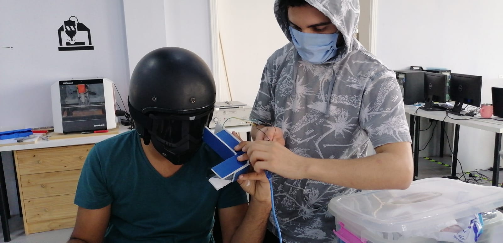
the thing that I was scare of it is how the screen will reflect and not disturb the rider, so I make Prototype about how it will lock and this help me in 3D design, the difficulties in this was how to give the good image and not disturb the rider how ever the hardies thing was to make the right angle.
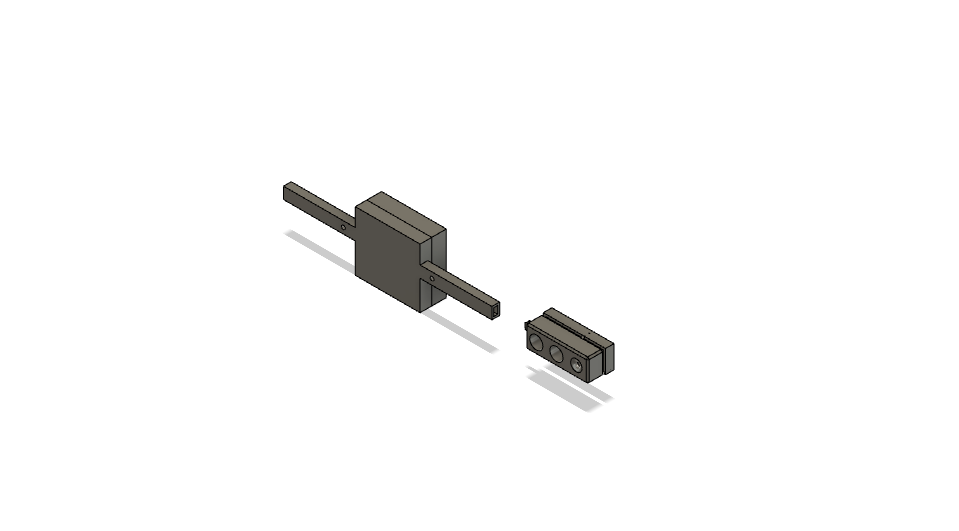
motorcycle device
for the motorcycle device it didn’t need a lot of time , I just case for the sensors and lights, and ecteronic part will be back of at plate number
Prototype shape
In these steps I tried to make Prototype of my device case, how it will fit the helmet and the view angle:
First thing I did wax making the case for the dive using fome
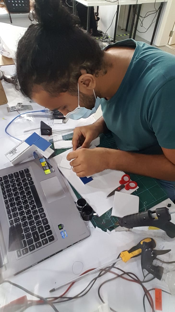
Next I want to know the angle of the helmet, So I start cutting small pieces and glow them in the helmet side by side for same the long of the case, then I glow them together and I added some support
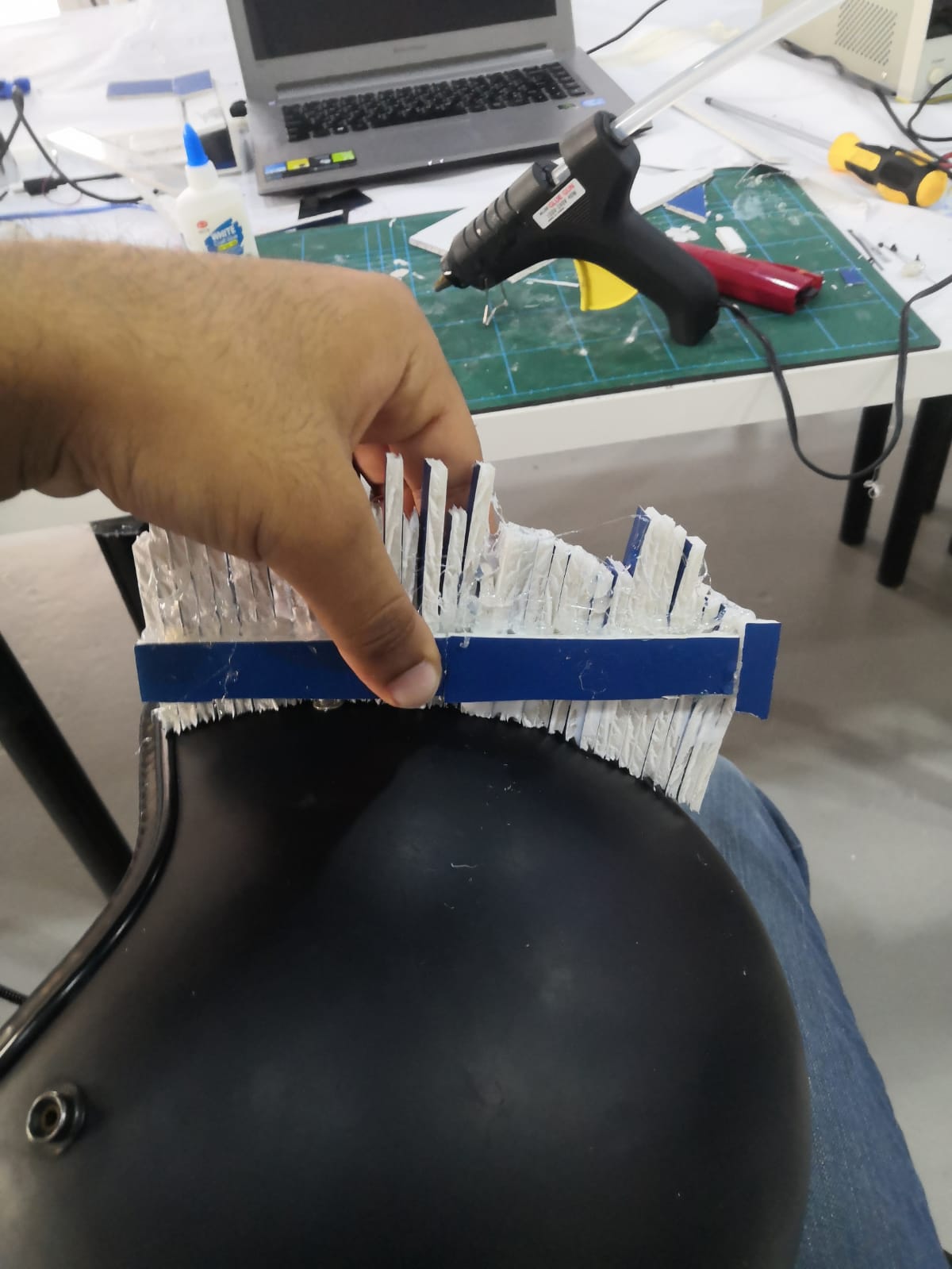
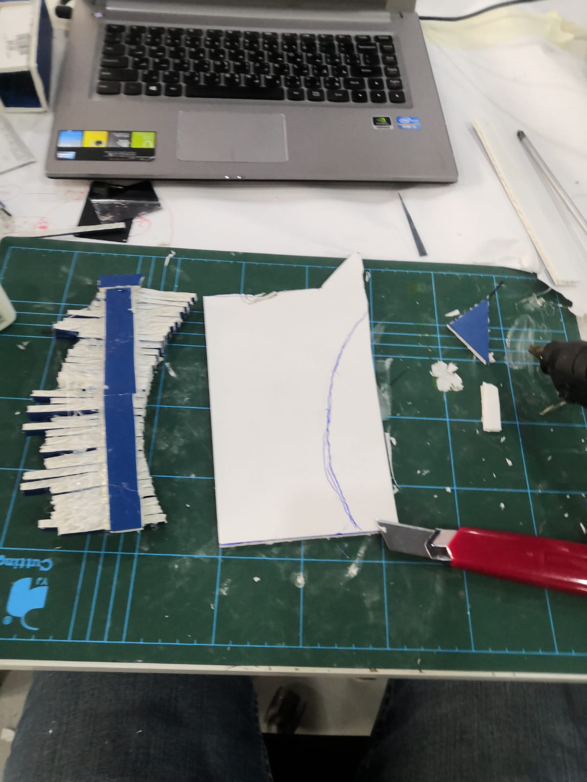
After that I remove it from the helmet and put in top of paper and make line on it, then I measured the angle by taking the height of the carve to the end line ever 1 cm, this will help me to do design.
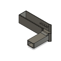
3D design
the first thing I print using was the helmet attachment
the second thing was the sensor case that fit on the plate number from the back
Bill of Materials
| Qty | Description | Price in BDH | Link | Notes |
|---|---|---|---|---|
| 1 | ATtinny44 | 0.200 | https://www.aliexpress.com/item/32281367838.html?spm=a2g0o.productlist.0.0.339e212ecKN53q&algo_pvid=07fa4a67-2ece-468b-a807-d31289e4c651&algo_expid=07fa4a67-2ece-468b-a807-d31289e4c651-1&btsid=0ab6fb8315948184789847111e4997&ws_ab_test=searchweb0_0,searchweb201602_,searchweb201603_ | |
| 1 | ATtinny84 | 0.250 | https://www.microchip.com/wwwproducts/en/ATtiny84 | |
| 1 | OLED 0.96 | 3.3 | https://www.instagram.com/p/B6Qt4sDgSxD/?igshid=1b5owey2d7wxe | |
| 2 | ultrasonic H5-SR04 | 1.5 | http://amazon.com/test | |
| 2 | Bluetooth H5-05 | 3 | https://www.instagram.com/p/CAGc_P0HvbD/?igshid=oadthz2uvdj1 | |
| 2 | battery 3.7v | 2.5 | http://amazon.com/test | |
| 2 | power booster mt3608 | 0.500 | https://ar.banggood.com/1pcs-MT3608-2A-DC-DC-Adjustable-Step-Up-Power-Module-Booster-Power-Module-p-1213134.html?cur_warehouse=CN |
where will they come from?
most of it I will order it online
who has done what beforehand?
there is some companies did prototype and other in the market .
what questions need to be answered?
how to the rider will see the information with out git disperses ? how I will connected the two devises ? how the devises will git powered ? how far the sensor can detected what behind the rider ?
how will it be evaluated?
if the rider have clear view to front and back and can change the line with out any problem.
plan
week 10 : I made circuit for the ultrasonic and every thing well good just need to make the connection.
in week 12 : I made the second circuit and put in it small screen but I have problem that the screen some times work and some not.
in week 13 : still try to fix the problem at the end of this week I fix it .
in week 14 : I made what the screen will show
in week 15 : I started to make the Bluetooth connection between the two circuit.
in week 16 : I am trying to fix the network problem
in week 17 : I start making the final case for both devices and put the reflector.
Problems
-my first problem that when I finished the code and try to upload to the ATtiny44 for the helmet device it wont be able to upload because of the size of the storage so I replace it with ATtiny84 because it have the double so storage size which it is 8000kb.
-the next problem was in the coding it was that I put “” instead of ‘’
files
I put here all the files for the Final Project .
3d design
helmet device case
motorcycle device case
Ecteronic design
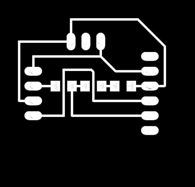
helmet device
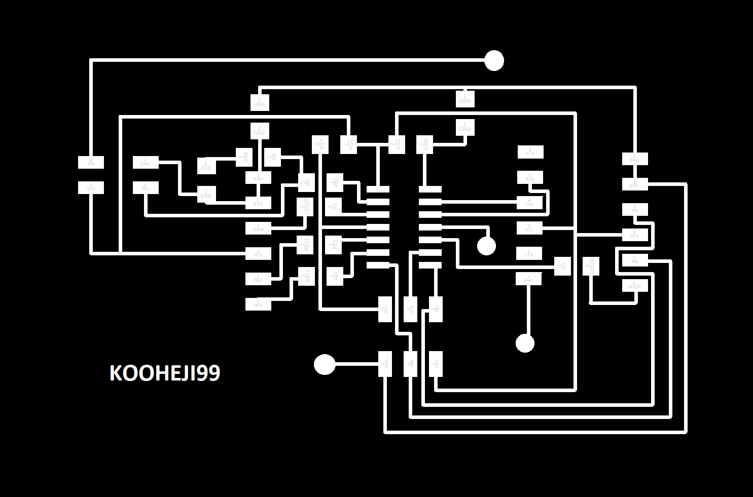
PCB1
traces :
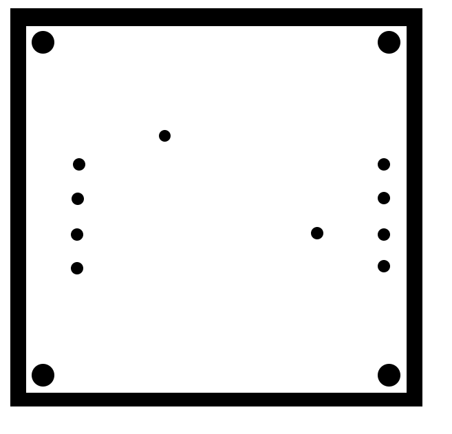
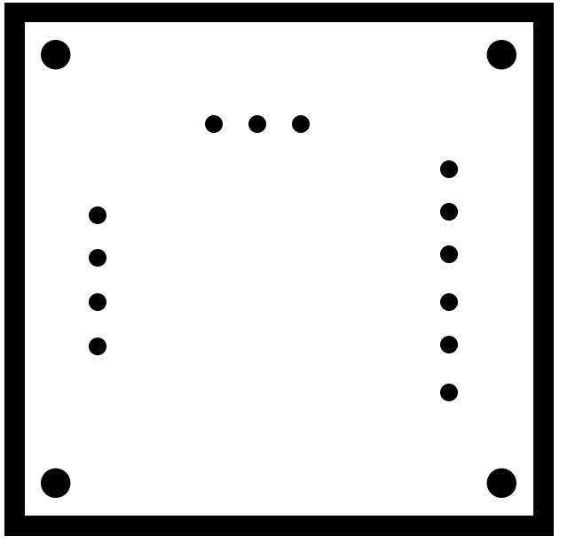
outline :
PCB2
traces :
outline :
motorcycle device
traces :
outline :

license

This work is licensed under a Creative Commons Attribution-NonCommercial-NoDerivatives 4.0 International License.