5. Electronics production
group Assignment
find more about it here
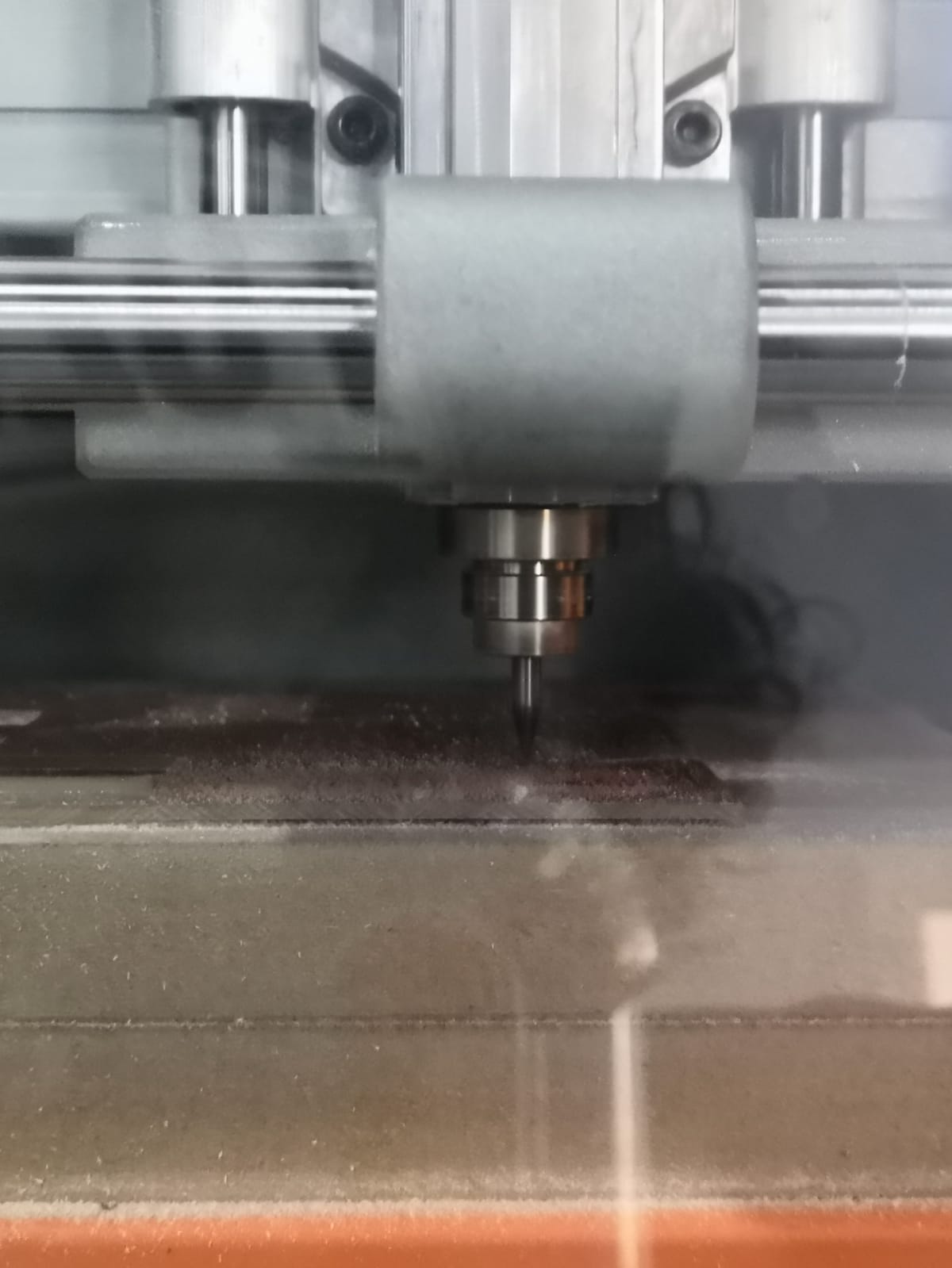
milling machine
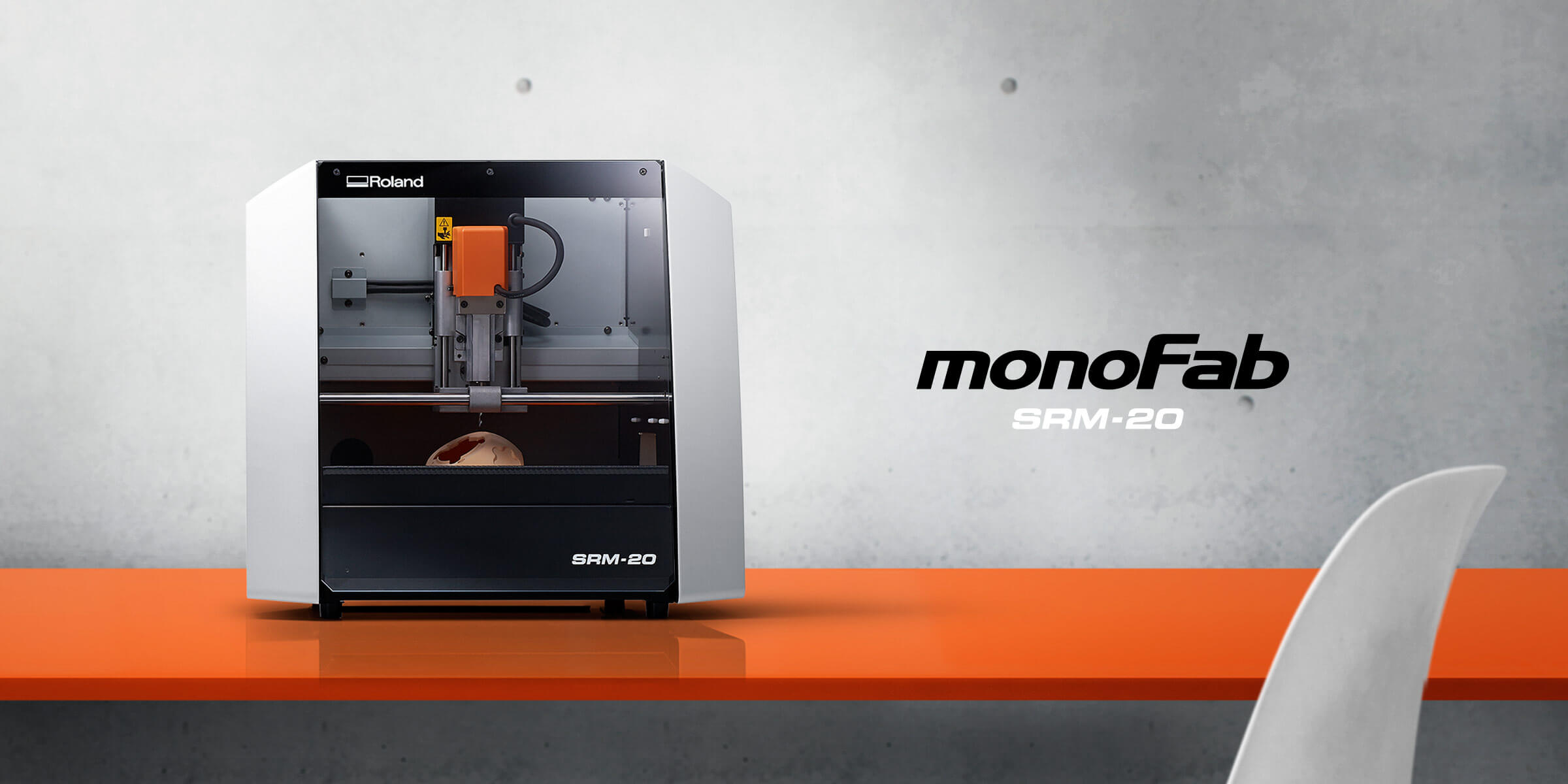
we have in our lab two milling machine “Roland Modela MDX20 CNC Mill” and “Roland SRM-20”. In this week use “Roland SRM-20” it eyes to use with good accurse .
The milling process
Before you use the machine you should prepare, the drill bite that you will use and you must know for it used and where you want to mill it must be balance so you don’t brick drill bit or the workpiece .
To start doing PCB we must put the circuit board in the machine in the wright way by placing the wood then circuit board and make sure that it balance using level bubble
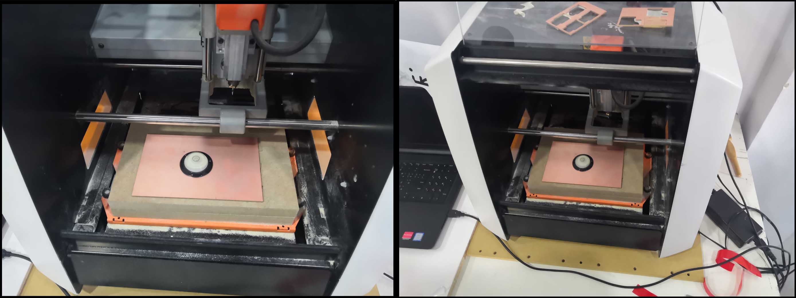
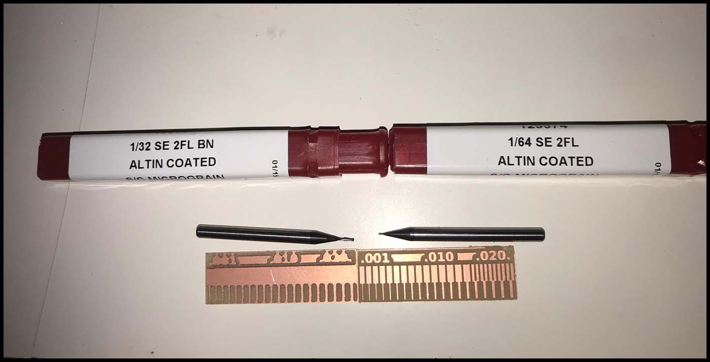
Then use the wright drill bit we have 1/32 and 1/64 we use the 1/64 to make the circuit lines and the 1/32 to cut it , Next setting origin point x and y but for z we make sure the bit don’t touch the board because it may break it so what we should do it to give it space then open the bit manually and make it touch the board carefully and we close it then set the z and every time that we change the bit we do this pressger, we finish prepare the machine .
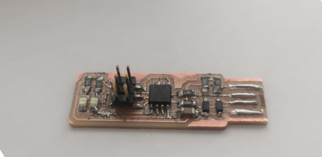
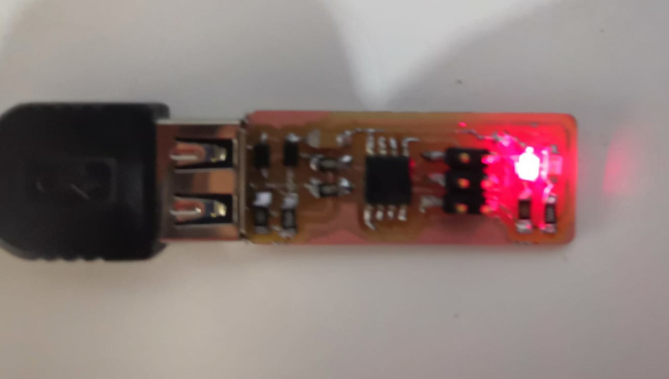
After that we are ready to use it , if we have the board Traces and outline and it must be a PNG file like This :
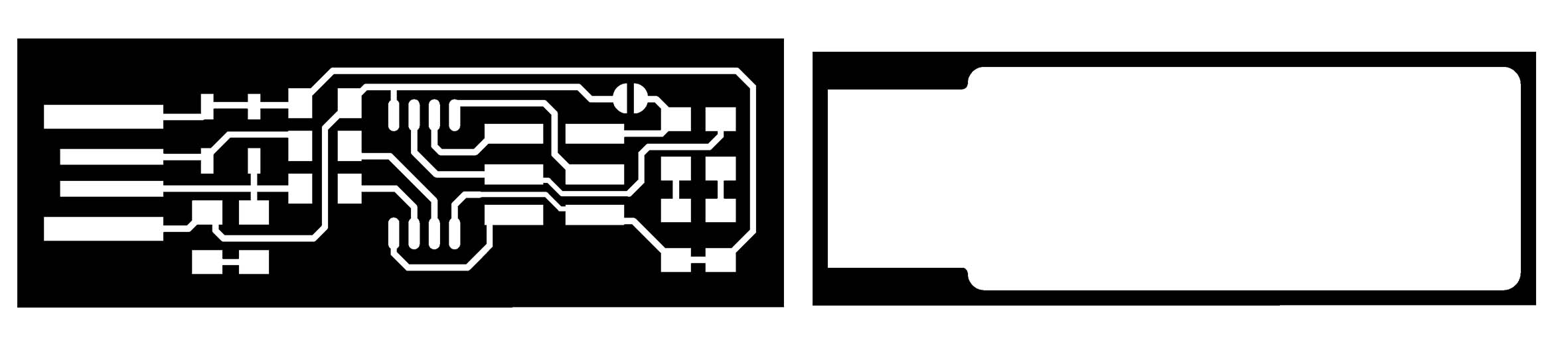 because the SRM-20 just understand black and white.
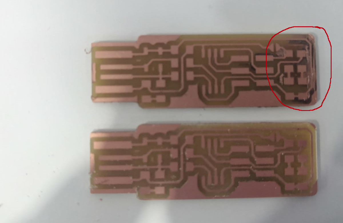
the first milling try there are two line that touch each other as you see in the red circle and the reason that I am thinking about what happened is the copper board wasn’t sick good in the bed and moved while it was milling .
Soldering
it is my second time to solder and it is my first time to solder this size
there is steps too make the soldering better and it is just four step 1. put the solder in the place and white for 3-5 s 2. the put the little
after I finish milling my board I start to bring the component near me and setup everything for soldering
the part that I user to do the programmer:
1x ATtiny45 or ATtiny85n
2x 1kΩ resistors
2x 499Ω resistors
2x 49Ω resistors
2x 3.3v zener diodes
1x red LED
1x green LED
1x 100nF capacitor
1x 2x3 pin header
I put all the part in paper and stick it by tape
like this way :
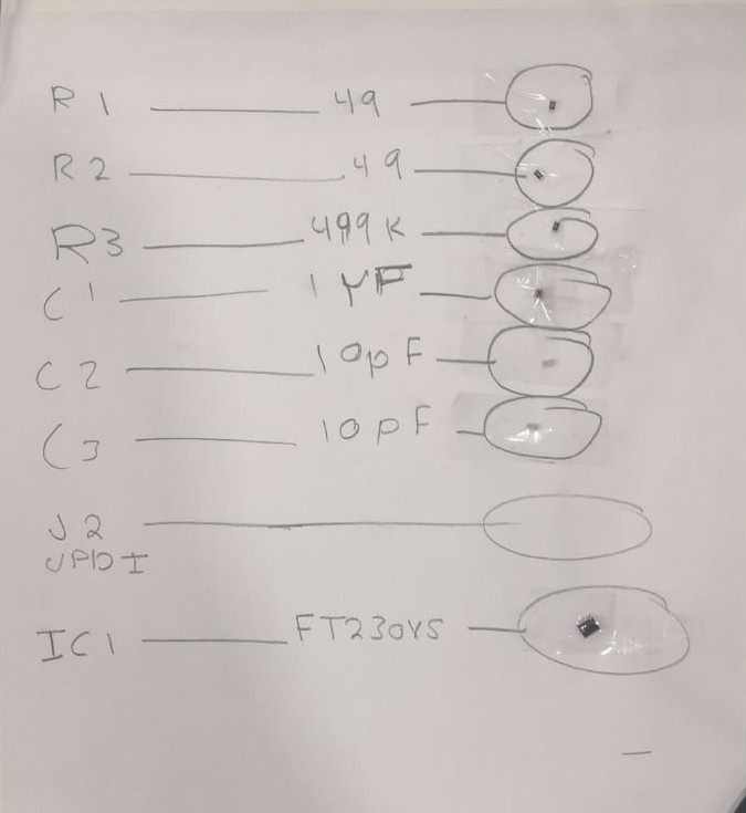
I write the name of the part and draw from line it and at the end of the line circle and I put the part inside it and stick it by tape
programmer
when I contacted in the computer the red LED light on and this that is working .
I highly recommend this page because it has a lot of detailed information about programming.
Steps for Mac
(1) Download CrossPack and firmware source code
(2) Run cd downloads >> cd fts_firmware_bdm_v1-3 >> make This will build the hex file that will get programmed onto the ATtiny45. When the command completes, you should now have a file called fts_firmware.hex
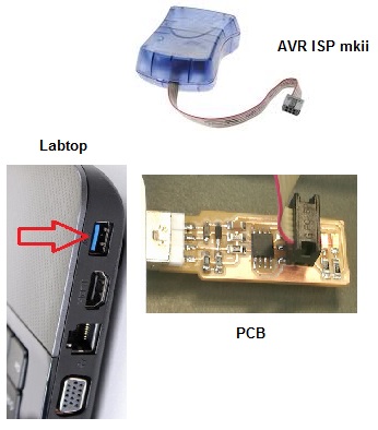
(3) Change programmer type that you will use to program the ATtiny45. Open fts_firmware_bdm_v1.zip >> Makefile change ” PROGRAMMER ?= usbtiny ” change usbtiny to the type of programmer you’re going to use .Then save the changes. In this case, the programmer I used was avrisp2.
Small translucent blue programmer: avrisp2
Large translucent blue programmer: jtag2isp
White box with blue stripe: atmelice_isp
(4) Using the two connections wire your PCB to your pc using USB port and in the other side ‘header’ to the programmer “avr isp mkii”. If your connection is right you have to see the color of the programmer if it was orange this means that the oriantation is wring or that you have a wronge connection. I the color was green this means that we are good to continue.
5) Run make flash To erase the target chip and program its flash memory with the information of the hex file we built.
(6) Run make fuses
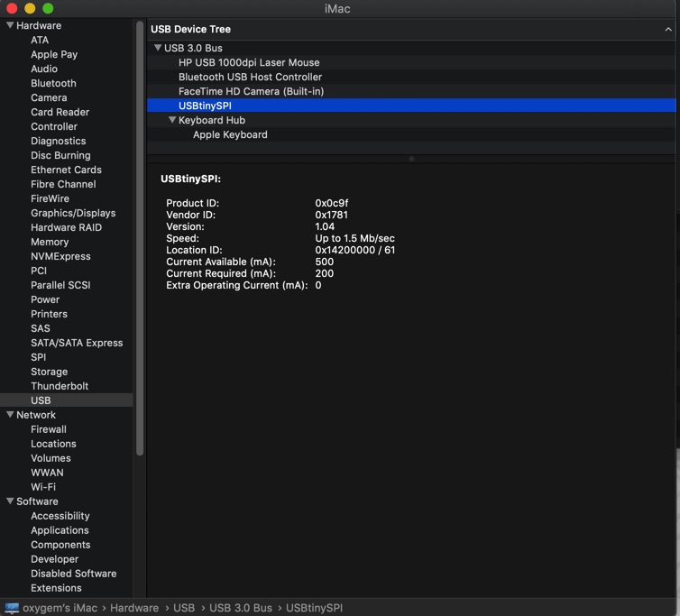
(7) Open Apple System Profiler (Apple Menu → About this Mac → More Information; or from the Utilities folder). Select USB from the list on the left, and you should see the USBTiny listed as a device on the right. If it shows up, it is working properly.
(8) Run make rstdisbl
(9) Remove jumper solder