14. Networking and communications
Group assignment
Individual assignment
I decided to test the serial networking for this week. The design used from Neil:
This design uses one bridge and one or more nodes.
The bridge will make direct connection to the computer, and to the first node. The first node will make connection to the next node, and so on.
Design process
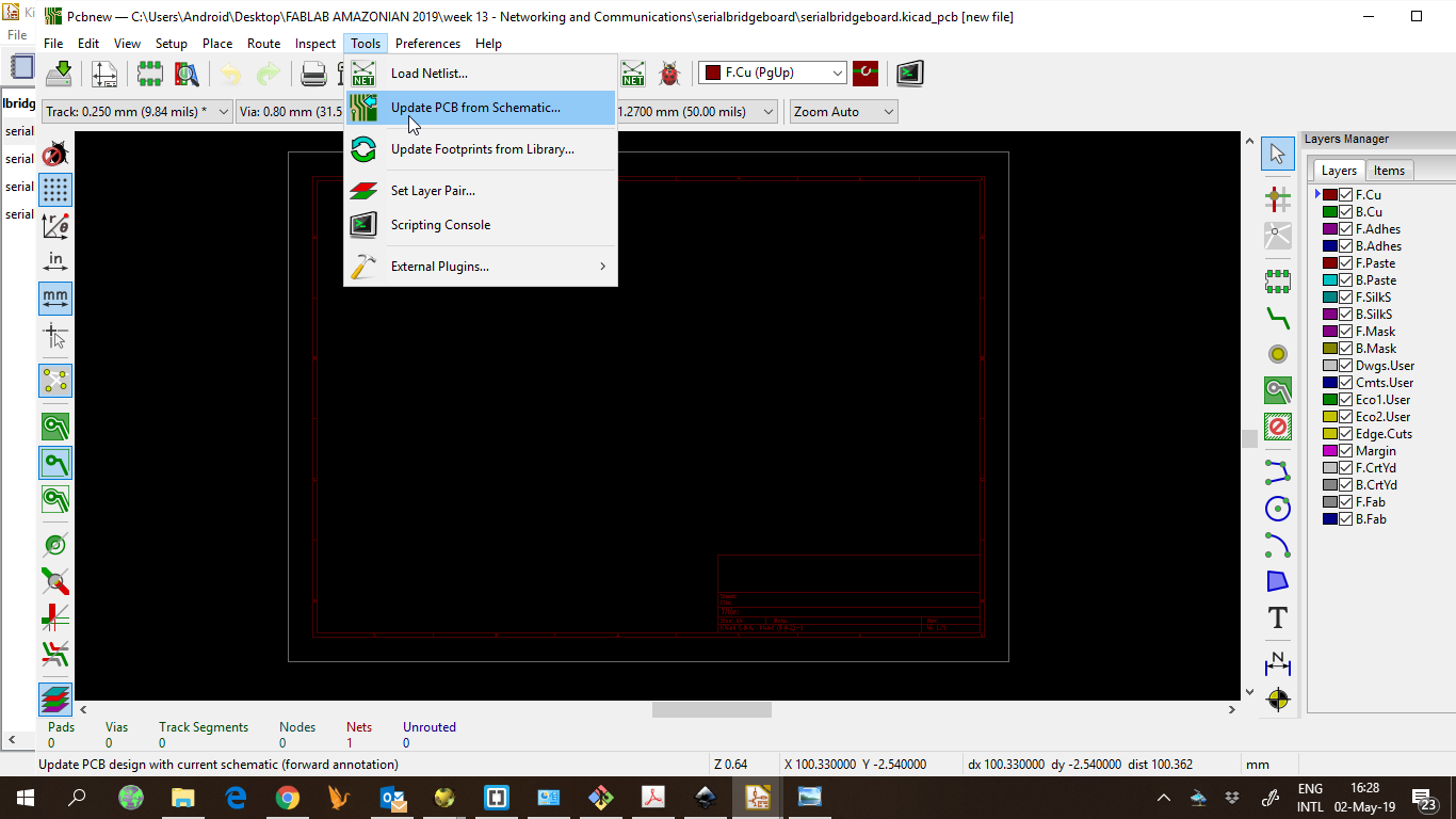
I started the kicad project and added the components to eeschema
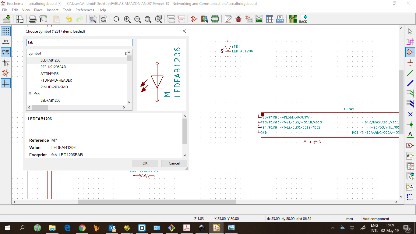
When finished, I annotated the components, assigned footprints and generated the netlist. Then, to pcbnew.
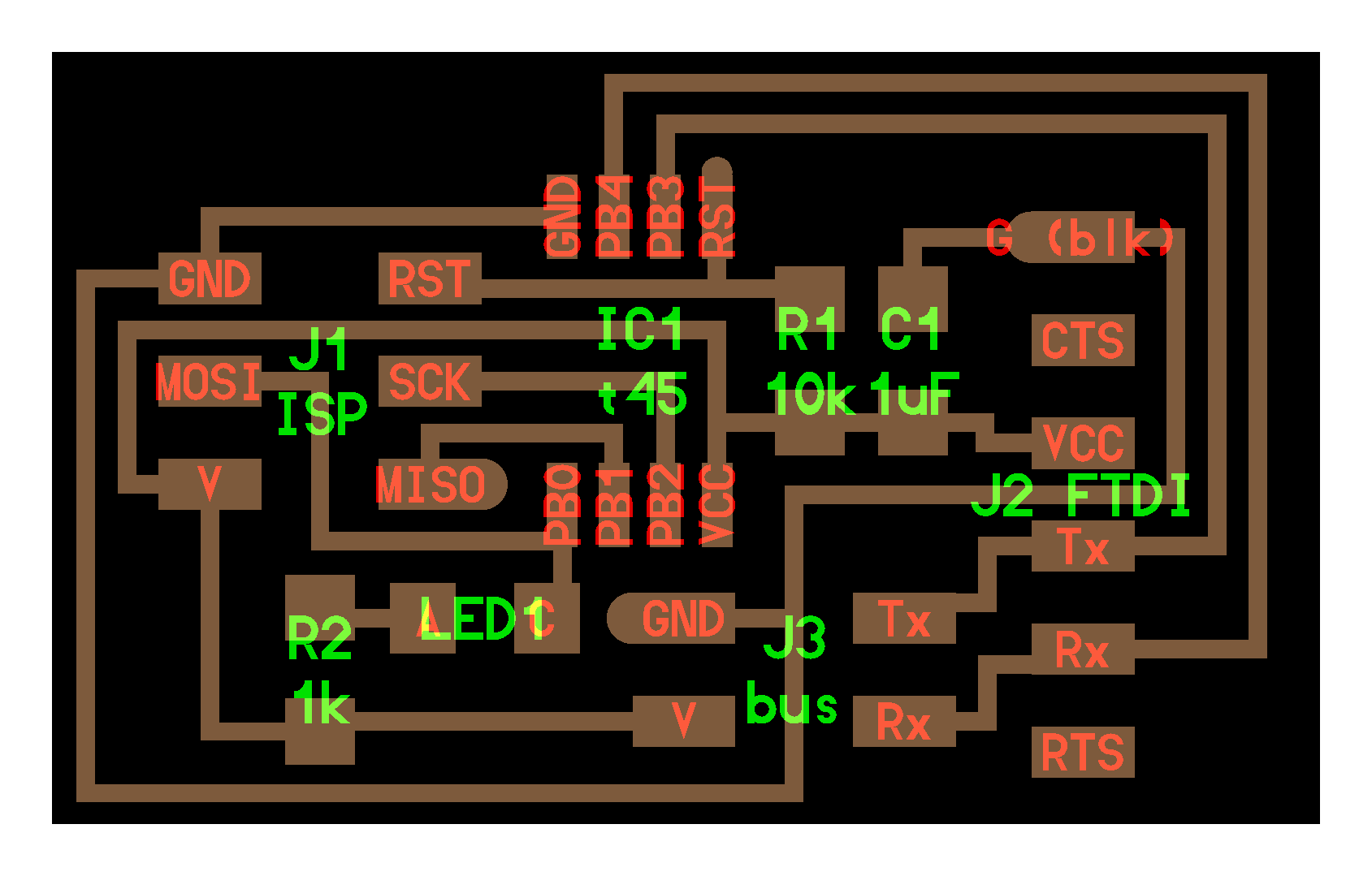
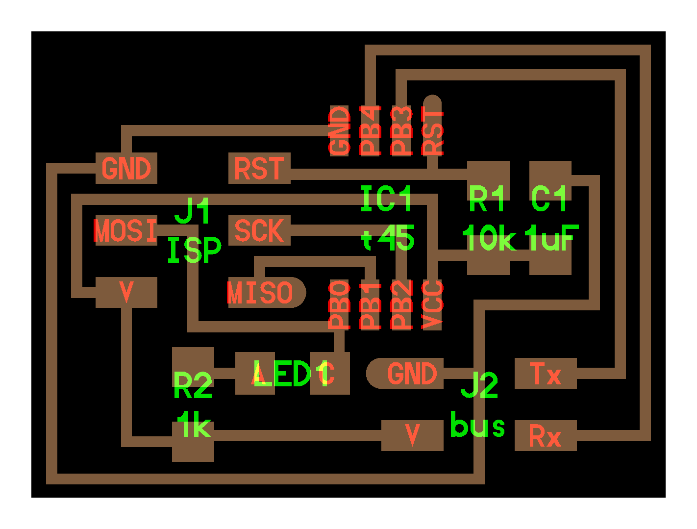
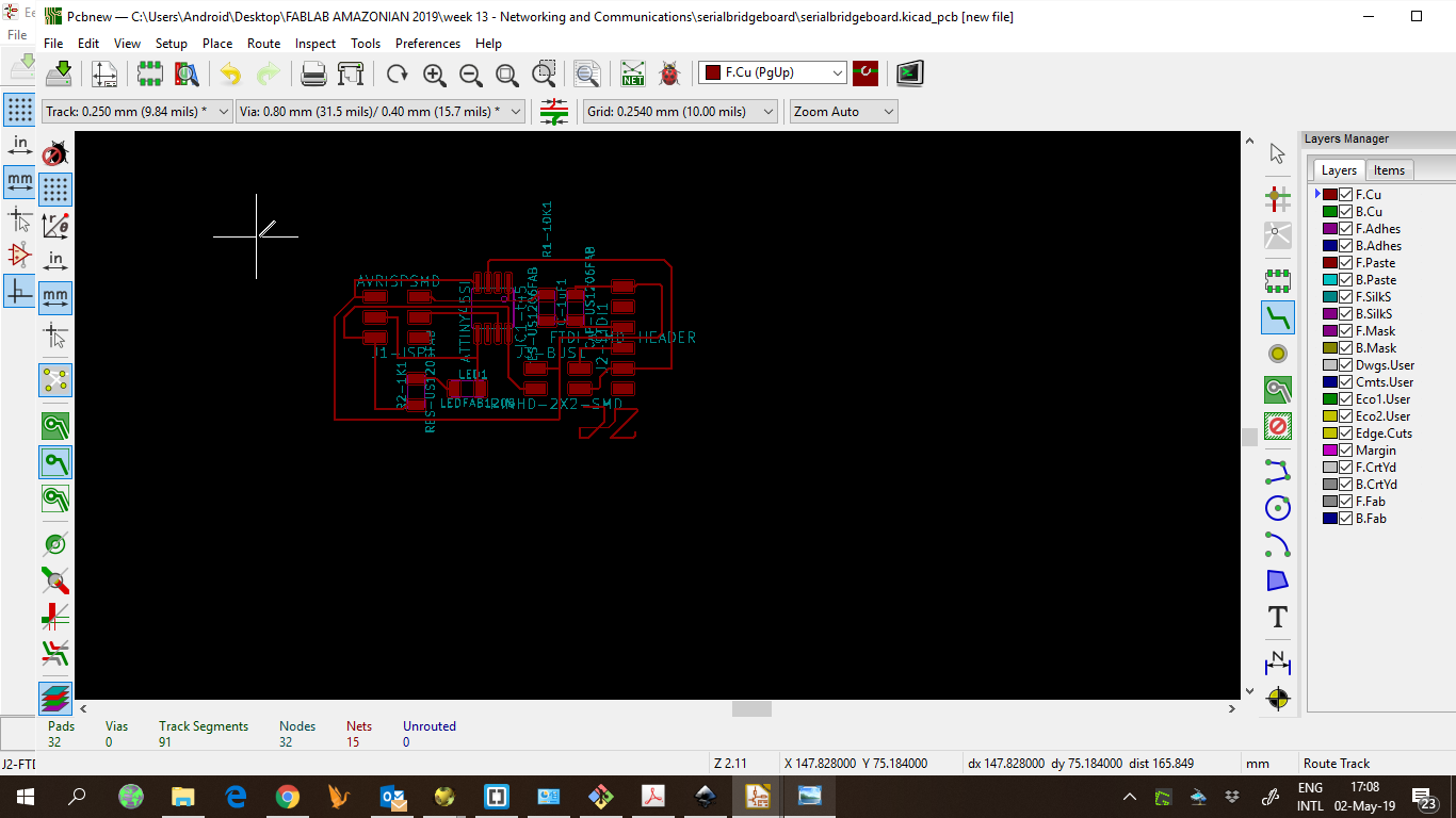
After that, I layed out my components.
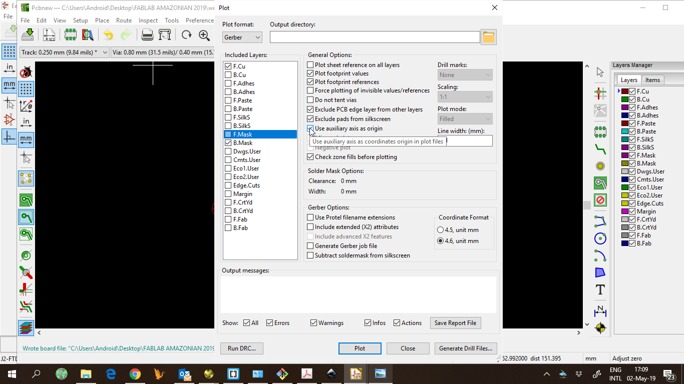
And generated the gerber files.
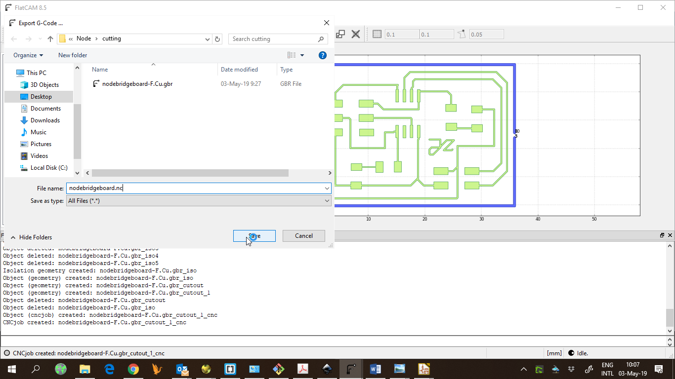
Then, open the gerber files in flatcam to generate the Gcode.
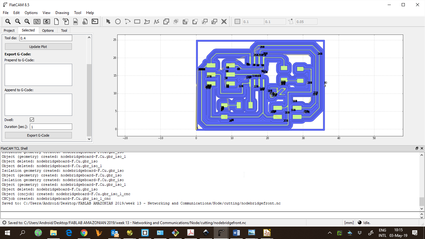
Parameters are: cut z: -0,15, feedrate: 60; tool dia: 0,4, spindle: 7000.
I also generated the toolpath for cutting the board.
Then, I use Candle to send the Gcode to the milling machine.
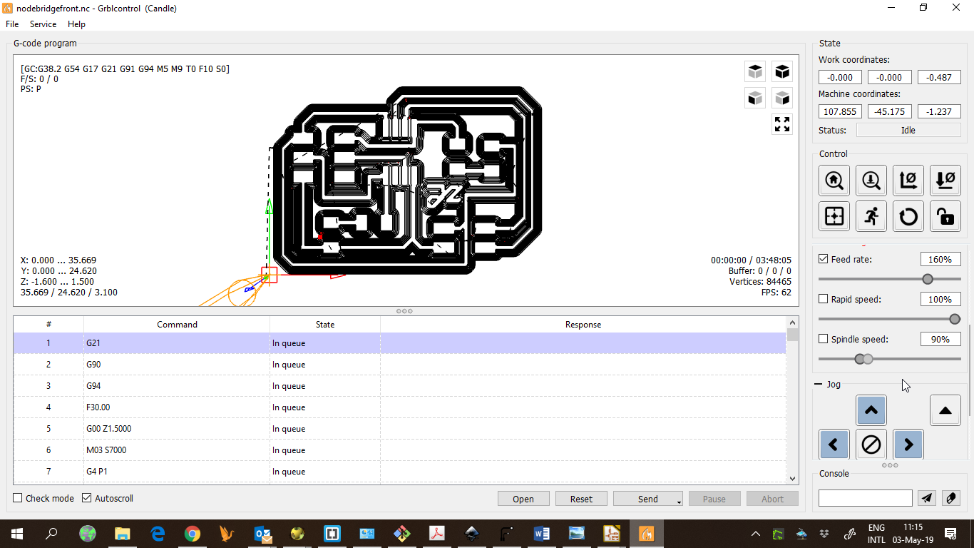
This machine and software allows to create a heightmap of the copper board surface, which improves the quality of the pcb milling process.
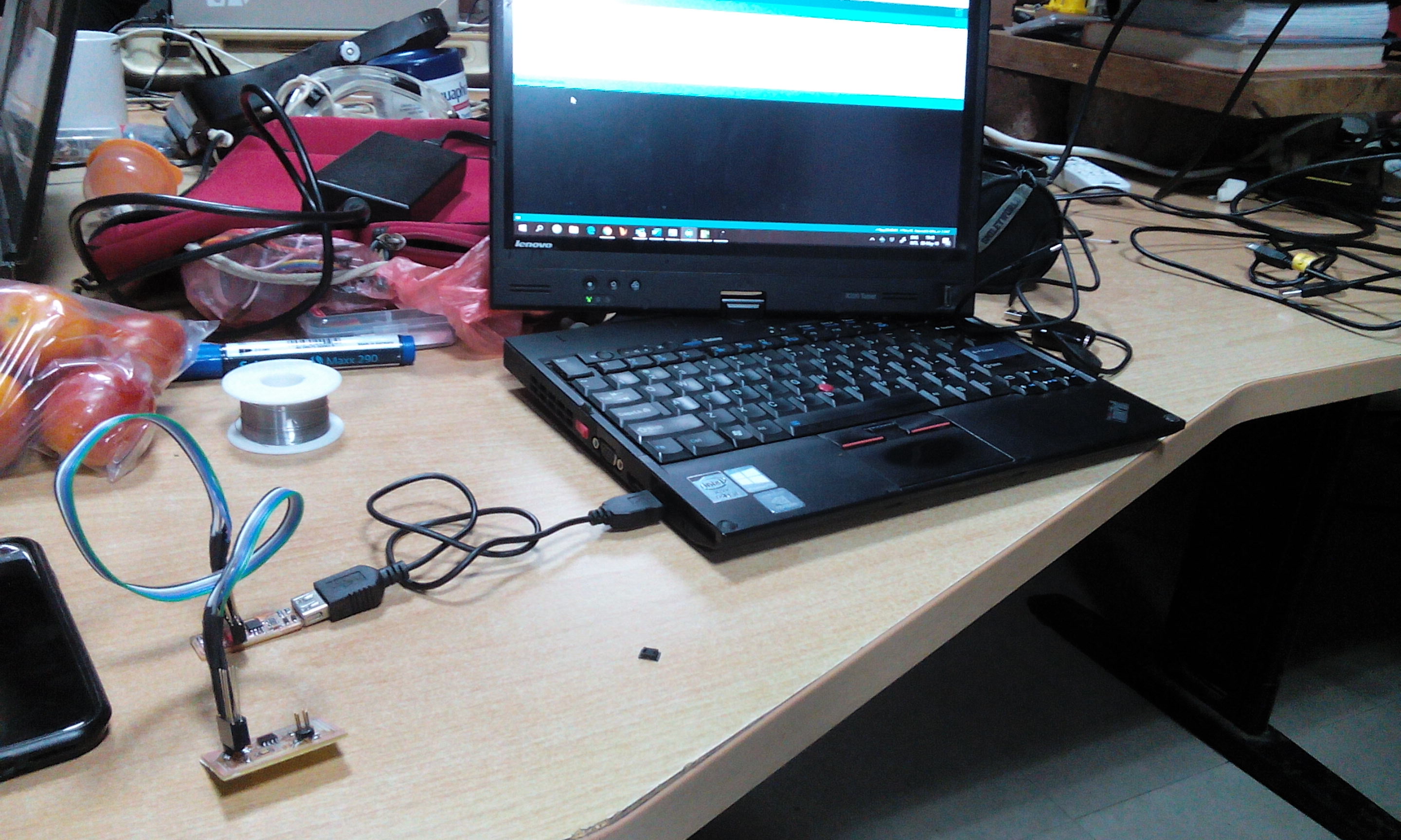
Programming the boards
Using the ISP programmer, I burned the bootloader to the bridge and the node and loaded The code for serial communication. I used Arduino IDE to upload the code. The aim is to have the node and the bridge communicate with each other via serial. This is done with the SR-232 standard
The code was used to understand the communication between the laptop and the boards through serial. It is simular as the netwerk of steppers drivers in the group assignment.
I learned that the communication can occur at the same time for more than one board, using a serial bus. The commuication is done through the TX and RX pins
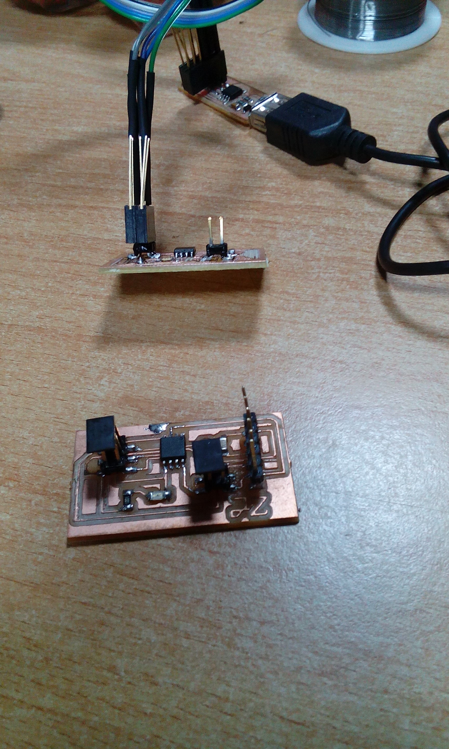
Communicating boards
Now, the boards are connected through serial, and each one responds when their address is sent thorugh Arduino serial monitor.
Note: I used another ISP programmer, it is the FABTinyISP the design
This version (the “FabTinyISP Minimal” is a minor revision to Zaerc’s version 0.3 (Bas), with small modifications Compared with the ISP programmer which i made in week 5 this is much easier to use because it connect straight into the computer or laptop without using an USB cable.
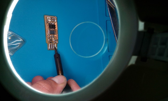
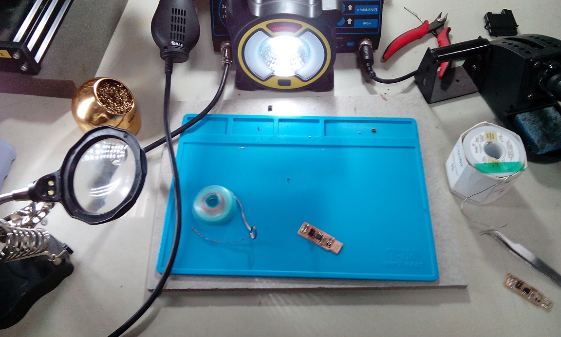
I designed the board and then soldered the components on it, make sure your working space is allways clean
At the end you can do the part which goes into the laptop
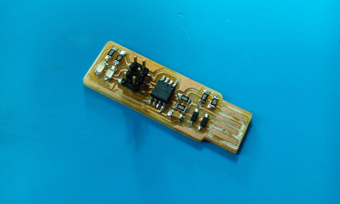
You heat up the cupper at meld the solder in one hit on it, make sure it has a good thickness. Because it has to fit and connect with your USB port.