15. Mechanical design
Group assignment
- Design a machine that includes mechanism+actuation+automation
- Build the mechanical parts and operate it manually
- Document the group project and your individual contribution
Brainstorming - Idea selection
- Drawing machine
- Scanning Machines
- Bambou machine
- Digital artist machine
Gather materials / Source physical parts
- Team A: Dave /Thibault / Theo Mechanical Design
- Team B: Shaf /Dave / Elvira Electronics Motor Driver Design
- Team C: Julie / Pascal / John Processing to Serial Communication + Motor Driver Programming
- Group : Documentation
- Coordinator: Theo
Test workflow
- Design the 3D enclosure using CAD Fusion 360.
- Laser cut the enclosure using plywood.
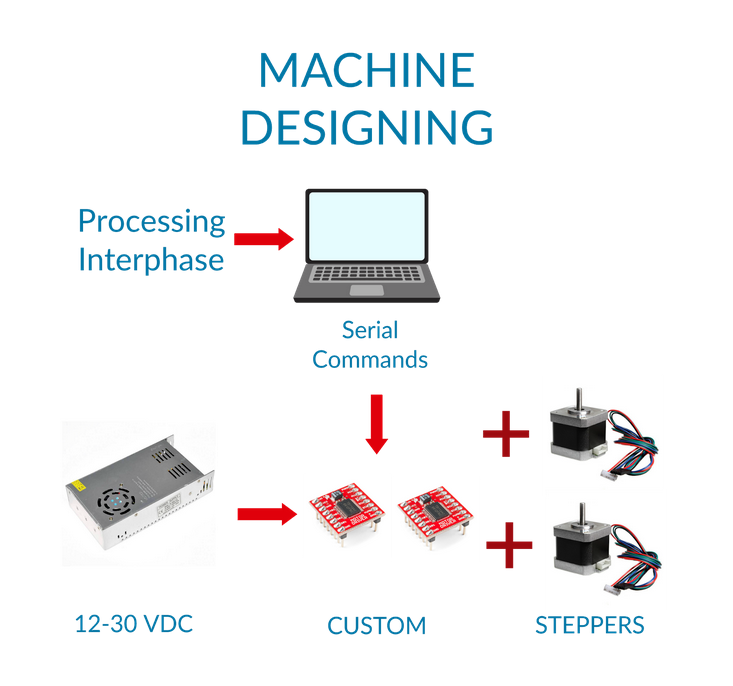
- Processing Installed/ Interphase Code / Serial Communication.
- Custom Motor Driver Design / Build / Test using Arduino Ide.
- Motor Driver Code Revamp Niels Code.
Idea
Digital Artist Project in a snap / CNC PLOTTER MACHINE
The idea is to build a digital artist with a simple interphase which is used to plot shapes.
How does it work?
The shape is created by importing our shape library into Processing Interphase which will be converted into commands and sent over serial to our custom motor drivers. Instructions will be received and actuated by Motor controllers build on ATtiny 45 or 44’s and steering nema17 or smaller motors on an XY system with a spring actuator holding a marker.
Gather Materials / Source Physical Parts
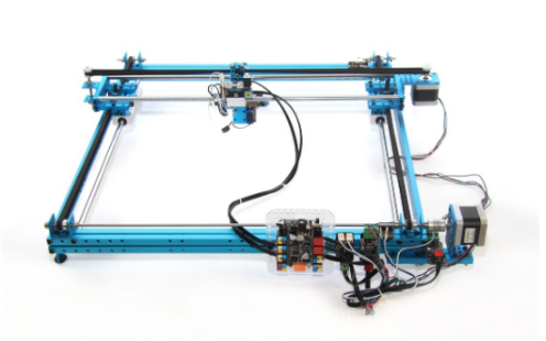
The first thing which we decided to do was to gather our materials. Our classmate had an existing makeblock plotter which was no longer in use so we decided to source shaft / linear bearing / belts from existing makeblock plotter machine.
Team A
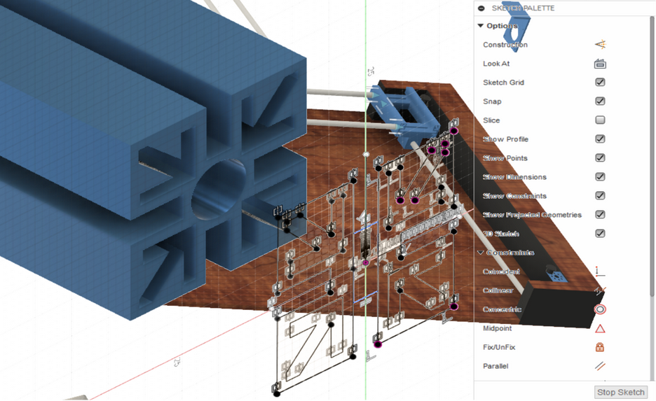
Together with my classmate Thibault we came up with an desighn for the machine. Afterwords I measured the parts to build a model using Fusion 360. You start with the sketch section where you select the basic shapes to construct your sketch. Next you select “Extrude” to create a body out of you sketch :
The same steps are taken for the rest of the machine except the pen holder:

I received the pen-holder parts from my classmate Shaf as an stl file.
After aligning up the parts, the design was ready for fabrication:

Afterwich I converted the design to an svg file and transferred it to Thibault for the machining process.
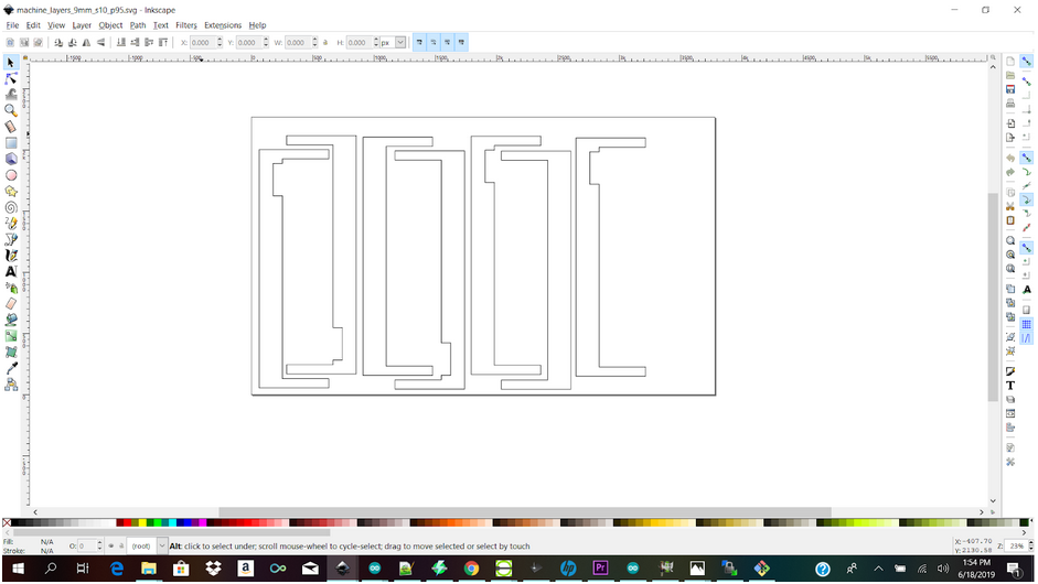
We then imported the fusion 360 files into inkscape to make sure the dimensions were correct, then import it into visicut and laser cut the frame.
Phase 2: Mechanical design reflexions
We started first with the idea that the machine should rest on a plywood panel which would represent the canvas and on which we would be able to attach sheets of paper. So, we took the pencil and the paper and we started to think about the wooden frame.
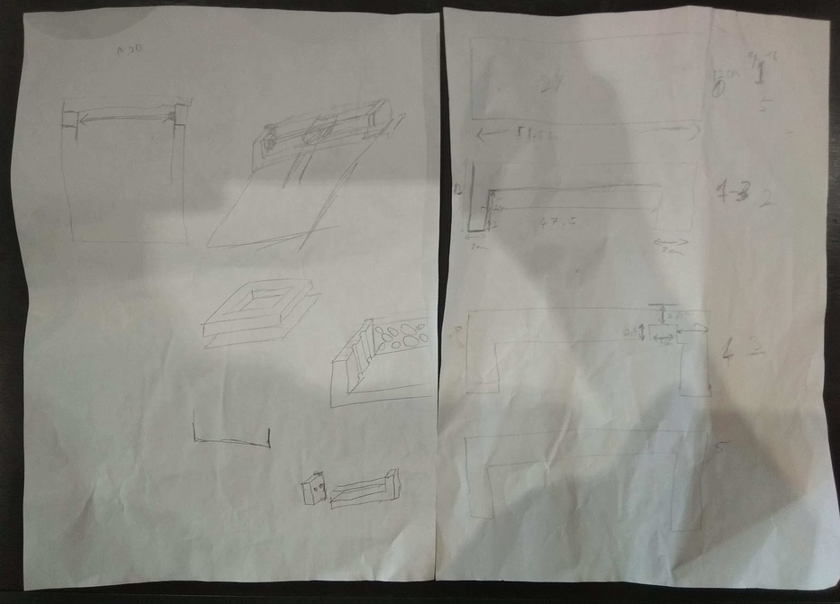
Sorry for the picture quality. The left side represent ideas of the wooden frame and how we wanted to have a frame capable of encapsulating the X arm. The idea was to attach the guide and the pulleys to this frame. The right side is describing how to build the frame by layers of lasercutted plywood. We also used fusion360 to check some of our measurment. These are available on Dave’s website.
Phase 3: Plywood machining first attempt
Since the big cnc machine is in Paramaribo we could’nt cut thick panel of plywood so I suggested the technique of copying lasercut 4mm plywood with the router.
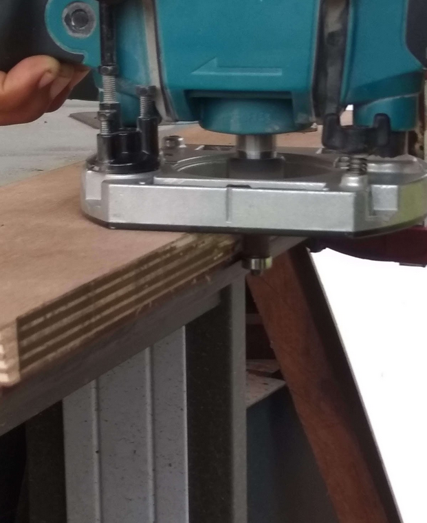
It went well since the ball bearing stucked. We hadn’t any more of these so we had to find another solution.
Phase 4: Lasercutting plywood
Instead of using 18mm we used 9mm that can be cut with the lasercutter. The cutting file is available here. Assembling 9mm layers is less resistant than 18mm but we though it could do the job.
We assembled the layers with screws from top and bottom.
The resistance was satisfying enough and we were able to go the step of attaching the other parts to the frame.
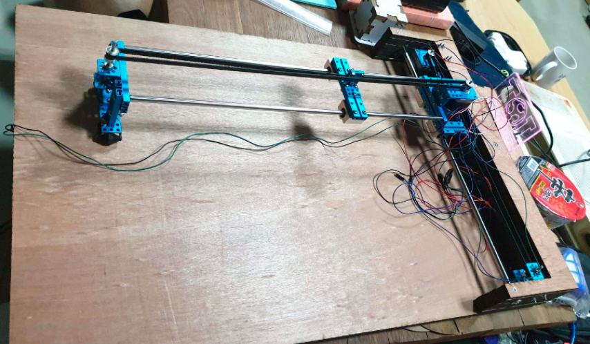
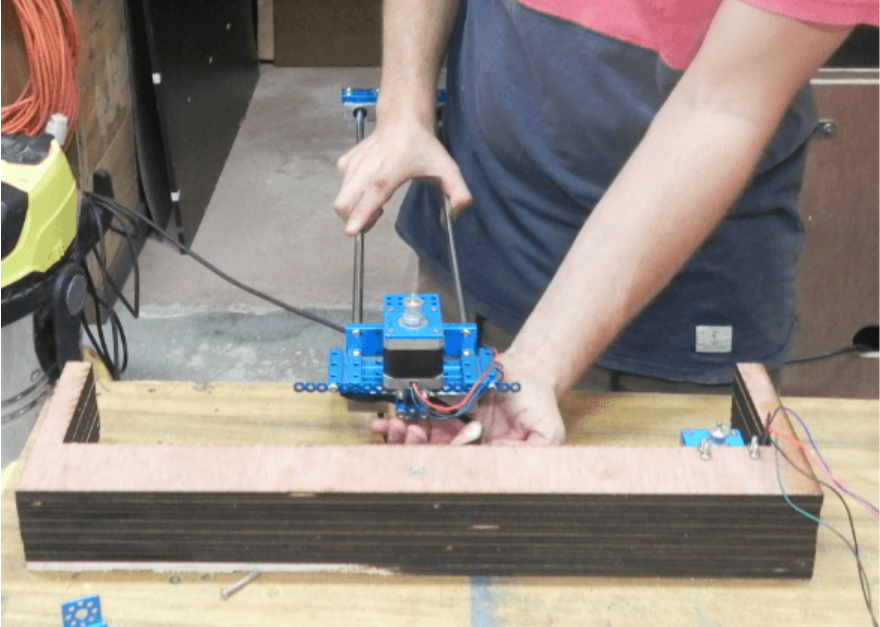
Phase 5: Machine assembly
The idea is to attach X guide on the wooden frame and to have it connected with Y guides.
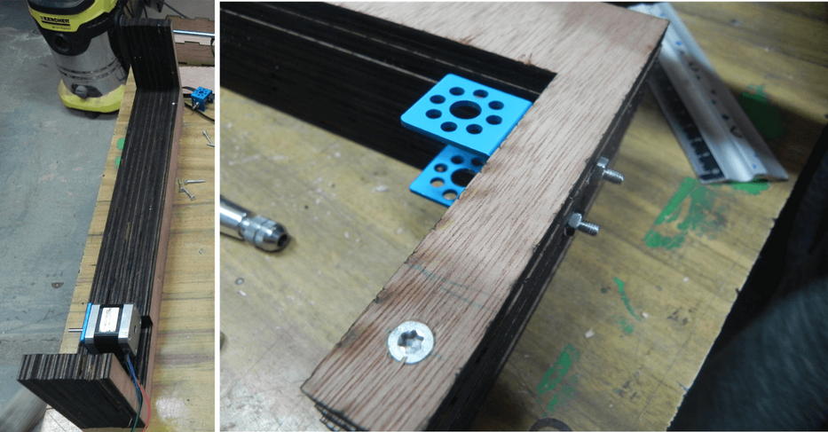
We first decided to attach the motor and the pulley holder. We had to make hole through plywood to be able to bolt these two parts. We were afraid of drilling parallel to layers (wood weakness) but everything went well.
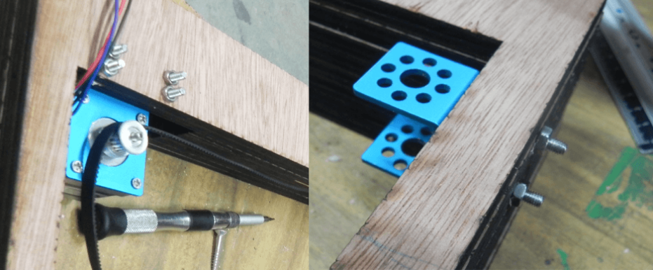
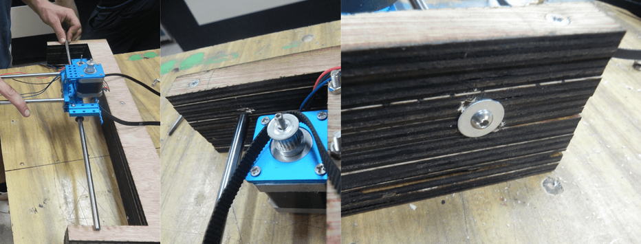
Then we took measurments to attach the guide at the good position. Guide has been assembled with screws and washers.
Eventually we cut the back panel and designed a roller caddie thanks to old robot parts. The constraint was for it to be at a good height to have approximately Y guides parallels to the back panel.
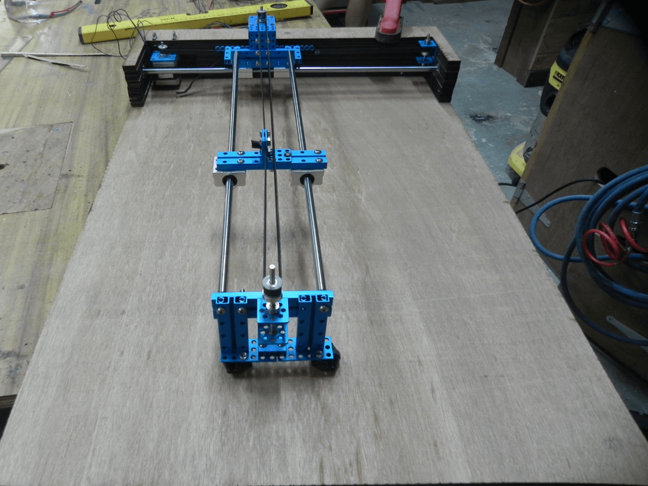
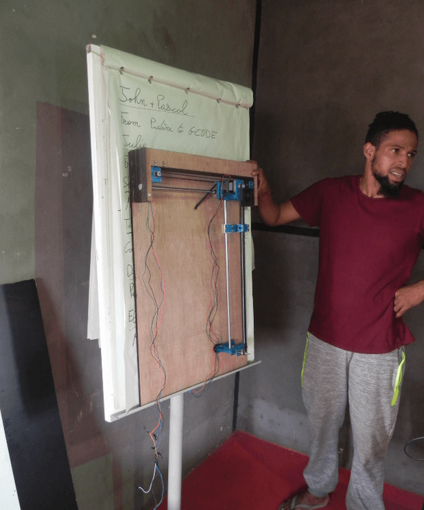
Here you can see Dave and the machine on a paperboard. Dave want to design an art stand for his “Do something big” assignment. These could give a very nice view of the machine.