9. Embedded programming
Group assignment
Compare the performance and development workflows for other architectures
Arduino Uno
Arduino Uno is a microcontroller board based on 8-bit ATmega328P microcontroller. Along with ATmega328P, it consists other components such as crystal oscillator, serial communication, voltage regulator, etc. to support the microcontroller. Arduino Uno has 14 digital input/output pins (out of which 6 can be used as PWM outputs), 6 analog input pins, a USB connection, A Power barrel jack, an ICSP header and a reset button.
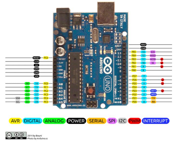
Program the Arduino Uno
I am going to use Arduino IDE to upload a blink sketch to the arduino uno and blink a led connected to arduino pin 13.
This is the code:
// the setup function runs once when you press reset or power the board
void setup() {
  // initialize digital pin LED_BUILTIN as an output.
  pinMode(13, OUTPUT);
}

// the loop function runs over and over again forever
void loop() {
  digitalWrite(13, HIGH);   // turn the LED on (HIGH is the voltage level)
  delay(1000);                       // wait for a second
  digitalWrite(13, LOW);    // turn the LED off by making the voltage LOW
  delay(1000);                       // wait for a second
}
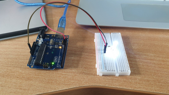
Setup and demo
Connect vcc on arduino pin 13 and connect the resistor from vcc to led pin and gnd to gnd on arduino uno pin.
Nodemcu devkit Processor
The NodeMCU (Node MicroController Unit) is an open source software and hardware development environment that is built around a very inexpensive System-on-a-Chip (SoC) called the ESP8266 . The ESP8266, designed and manufactured by Espressif Systems , contains all crucial elements of the modern computer: CPU, RAM, networking (wifi), and even a modern operating system and SDK .
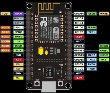
The nodemcu devkit is 1. An open source ESP8266 firmware that is built on top of the chip manufacturer’s proprietary SDK. The firmware provides a simple programming environment based on eLua (embedded Lua ), which is a very simple and fast scripting language with an established developer community. For new comers, the Lua scripting language is easy to learn. 2. A DEVKIT board that incorporates the ESP8266 chip on a standard circuit board. The board has a built-in USB port that is already wired up with the chip, a hardware reset button, wifi antenna, LED lights, and standard-sized GPIO (General Purpose Input Output) pins that can plug into a bread board. Figure 1 shows the DEVKIT board, and Figure 2 shows the schema of its pins.
Program the NodeMCU
Copy the below code in the Additional boards Manager: (http://arduino.esp8266.com/stable/package_esp8266com_index.json)
Then: 1. Board: NodeMcu 1.0 (Esp-12E Module) 2. Upload Speed: 115200 3. CPU frequency: 80MHz 4. Select your COM Port 5. Programmer: AVRISP mkll I am going to use Arduino IDE to upload a blink sketch to the arduino uno and blink a led connected to arduino pin 13.
This is the code:
// the setup function runs once when you press reset or power the board
void setup() {
  // initialize digital pin LED_BUILTIN as an output.
  pinMode(13, OUTPUT);
}

// the loop function runs over and over again forever
void loop() {
  digitalWrite(13, HIGH);   // turn the LED on (HIGH is the voltage level)
  delay(1000);                       // wait for a second
  digitalWrite(13, LOW);    // turn the LED off by making the voltage LOW
  delay(1000);                       // wait for a second
}
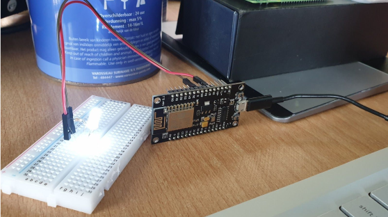
Setup and demo
For this example I have used NodeMCU esp8266 and if you are using any other vendor wifi chips or generic wifi module please check with the esp8266 Pin mapping which is very essential to make things works.The reason why I used D7 p in for this example is , I uploaded the basic blink program that comes with the examples program in the arduino IDE which is connected with 13 pin of arduino. The 13th pin is mapped into D7 pin of NodeMCU.
Web server on NodeMCU
This is the code:
Webserver
#include <ESP8266WiFi.h>
// Connect you our home network
//SSID and Password
const char* ssid = "telew_f29";
const char* password = "2c0f8319";
//Selecting Pin 13 for arduino which maps to D7 Nodemcu devkit
int ledPin = 13; // GPIO13
//Setting up webserver on port 80
WiFiServer server(80);
void setup() {
//Starting serial on baud rate 115200
Serial.begin(115200);
//Waits for 1 second
delay(10);
//Setting ledPin as output
pinMode(ledPin, OUTPUT);
//Turn led off
digitalWrite(ledPin, LOW);
// Connect to WiFi network
Serial.println();
Serial.println();
Serial.print("Connecting to ");
Serial.println(ssid);
WiFi.begin(ssid, password);
while (WiFi.status() != WL_CONNECTED) {
delay(500);
Serial.print(".");
}
Serial.println("");Serial.println("WiFi connected");
// Start the server
server.begin();
Serial.println("Server started");
// Print the IP address
Serial.print("Use this URL to connect: ");
Serial.print("http://");
Serial.print(WiFi.localIP());
Serial.println("/");
}
void loop() {
// Check if a client has connected
WiFiClient client = server.available();
if (!client) {
return;
}
// Wait until the client sends some data
Serial.println("new client");
while(!client.available()){
delay(1);
}
// Read the first line of the request
String request = client.readStringUntil('\r');
Serial.println(request);
client.flush();
// Match the request
int value = LOW;
if (request.indexOf("/LED=ON") != -1) {
digitalWrite(ledPin, HIGH);
value = HIGH;
}
if (request.indexOf("/LED=OFF") != -1) {
digitalWrite(ledPin, LOW);
value = LOW;
}// Set ledPin according to the request
//digitalWrite(ledPin, value);
// Return the response
client.println("HTTP/1.1 200 OK");
client.println("Content-Type: text/html");
client.println(""); // do not forget this one
client.println("<!DOCTYPE HTML>");
client.println("<html>");
client.print("Led pin is now: ");
if(value == HIGH) {
client.print("On");
} else {
client.print("Off");
}
client.println("<br><br>");
client.println("<a href=\"/LED=ON\"\"><button>Turn On </button></a>");
client.println("<a href=\"/LED=OFF\"\"><button>Turn Off </button></a><br />");
client.println("</html>");
delay(1);
Serial.println("Client disconnected");
Serial.println("");
}
Demo
Raspberry pi 3
For the next example I will be using the Raspberry pi 3
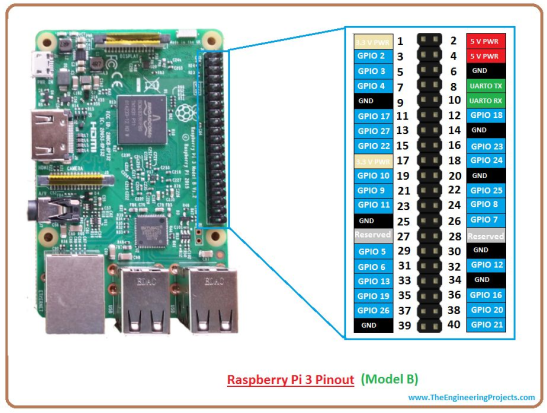
Program the Raspberry pi 3
- Download raspbian image I am using Jessie for Raspberry pi 3 but you can download the latest image raspbian stretch from here (https://www.raspberrypi.org/downloads/). Note:Raspbian Jessie does not boot on raspberry pi 3 I am using raspbian Wheezy download here (https://sourceforge.net/projects/raspbian-wheezy-pi/)
- Write the image to the sd card im using Windiskimager you can download it from here (https://sourceforge.net/projects/win32diskimager/). Once you have WinDiskImager installed and you have inserted your sd card into your laptop open WinDiskImager and select which sd card driver mine is on F. Then go ahead and navigate to where your image is and write image to device.
- Once that is completed go ahead and open the sd card file system and edit cmdline.txt and add an ip address which you would like to use to find your raspberry pi on your network mine for example is 192.168.x.x so add at the end of the file ip= 192.168.x.x
- And add and empty file in the root of the file system called ssh with no extension. Note if you are connecting to your raspberry pi headless for the first time this is needed to enable ssh so you can use putty to program your raspberry pi.
- Go ahead and download putty to connect to your raspberry pi you can download it from here (https://www.putty.org/) Open it and type in your raspberry pi ip address and click open. Default login is root and password is raspberry
- Go ahead and do python –version to check your python version mine is 2.7.9
- Once loged in go ahead and make a folder called Blink with the mkdir command and navigate into it and do nano blink.py to make a file called blink.py and paste the blink code into it.
This is the code:
from gpiozero import LED
from time import sleep

led = LED(17)

while True:
    led.on()
    sleep(1)
    led.off()
    sleep(1)
- Do ctrl x then y to exit and save code.
- Then do python blink.py
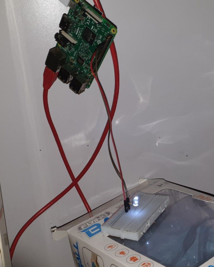
Setup and demo
Have ping 9 (GND) connected to negative leg of led and pin 11 (GPIO 17) connected to positive leg of Led and resistor connected from gpio 17 to positive led leg
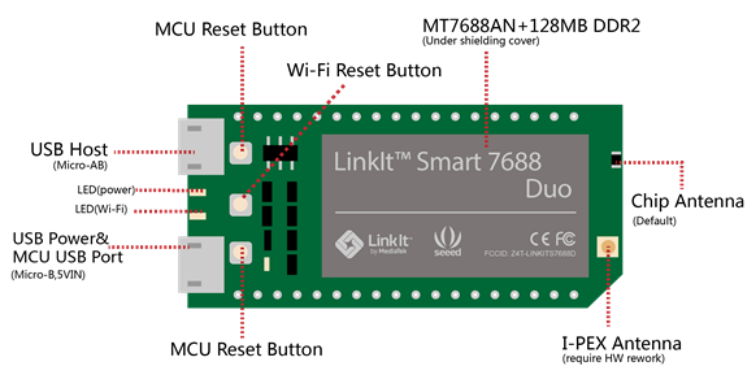
Linkit Smart 7688 Duo
LinkIt Smart 7688 Duo is an open development board compatible with Arduino Yún sketches, based on the OpenWrt Linux distribution, MT7688 and ATmega32u4. The board is designed especially to enable the prototyping of Rich IoT Application for smart house or office. Since it is compatible with Arduino, this allows you to use different features from Arduino Yún and LinkIt Smart 7688 Duo, which will help you build rich applications based on various, robust and compiled Arduino Yún sketches. The board offers you the memory and packet storage to enable robust video processing. The platform also offers options to create device applications in Python, Node.js and C programming language.
Features:
-580 MHz MIPS CPU -Single input single output(1T1R) Wi-Fi 802.11 b/g/n (2.4G) -Pin-out for GPIO, I2C, SPI, SPIS, UART, PWM and Ethernet Port -32MB Flash and 128MB DDR2 RAM -USB host -Micro SD slot -Support for Arduino (ATmega32U4)
Program the LinkIt Smart 7688 Duo
Open Arduino IDE and on the File menu click New, then copy and paste in the following code:
void setup() {
Serial.begin(115200); // open serial connection to USB Serial
//port(connected to your computer)
Serial1.begin(57600); // open internal serial connection to
//MT7688
pinMode(13, OUTPUT); // in MT7688, this maps to device
}
void loop() {
int c = Serial1.read();
// read from MT7688
if (c != -1) {
switch(c) {
case '0':
// turn off D13 when receiving "0"
digitalWrite(13, 0);
break;
case '1':
// turn on D13 when receiving "1"
digitalWrite(13, 1);
break;
}
}
}
Create python program to send commands to sketch:
import serial
import time

s = None

def setup():
    # open serial COM port to /dev/ttyS0, which maps to UART0(D0/D1)
    # the baudrate is set to 57600 and should be the same as the one
    # specified in the Arduino sketch uploaded to ATMega32U4.
    global s
    s = serial.Serial("/dev/ttyS0", 57600)


def loop():
    # send "1" to the Arduino sketch on ATMega32U4.
    # the sketch will turn on the LED attached to D13 on the board
    s.write("1")
    time.sleep(1)
    # send "0" to the sketch to turn off the LED
    s.write("0")
    time.sleep(1)


if __name__ == '__main__':
    setup()
    while True:
        loop()