5. Electronics production
Group assignment
Characterize the design rules for your PCB production process
Milling machine
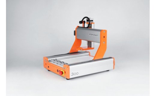
| STEPCRAFT-2 D.300 | Value |
|---|---|
| Clamping surface (x,y) | 222mm x 380mm |
| Working space (x,y,z) | 210mm x 300mm x 80mm |
| Programmable resolution | 0.005mm |
| Maximum speed | 3000mm/min or 50mm/s |
| Spindle | Stepcraft HF500 |
| Weight | 13 kg |
| Interface | USB or parallel |
| Software | WinPC-NC |
First tests
The milling machine came as an assembly kit, so it required a few hours to put toghether, and a fwe hours to calibrate, align, and adjust.
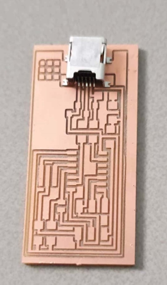
The end mills available were 0,40 mm for routing and 0,80 mm for cutting. And when the machine was ready to be tested, we found out that the end mills flutes were too long, so they broke easily. To avoid that, we lowered the feed rate drastically. These were our settings:
| Parameter | Value |
|---|---|
| Cut z | -0,15 mm |
| Passes | 2 |
| Travel z | 25 mm |
| Feed rate | 0,5 mm/s |
| Spindle speed | 10 000 |
During the first test, we were confused by the behaviour of the machine. After some testing and tweaking, we found that the software WinPC-NC assumes that -z is up and +z is down, so our settings from FlatCAM for cut z and travel z were not behaving as expected.
There are two ways to solve that:
- In FlatCAM: use a positive value for cut z and a negative value for travel z.
- In WinPC-NC: activate the option “invert z coordinates” in the software parameters.
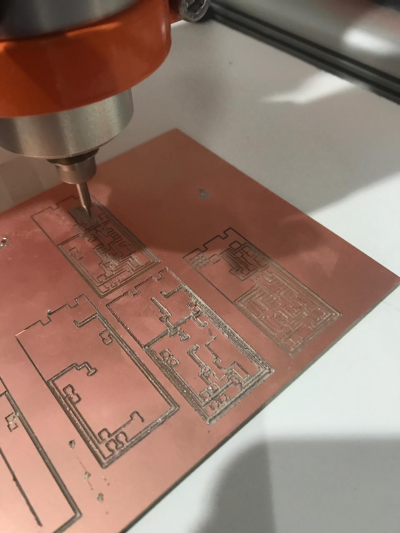
Second test
Eventualy, we found other software parameters that need to be checked on the milling machine before starting a job:
- Set job origin to “origin of coordinates”.
- Set start/end position to “zero point”.
After a few tests, we started milling boards with only one pass. Even when that is not ideal, it takes a really long time to mill at 0,5 mm/s, so we decided to go with one pass until we get new end-mills.