11. Input devices
I have two devices to describe for this week. The first was a design I prepared for last year’s assignment, which read a simple strain-gauge set-up and amplified it to a level which could be read with a DAQ system. The second is part of a research project developing some new flow sensors - my circuit will read and amplify a pressure transducer signal so that it can be compared to the flow measurements made by the new sensors.
Strain-gauge Reader
The plan for this exercise is to use my bird-board from week 8 to start making the measurements I’m going to need when I get around to building my submersible robot. The Tritalchen will have flexible spines and a skin stretched between them. I’m going to want to measure the strain throughout the skin, to compare with the local water flow. So the objective for this week is to start reading strain gauges - the step gauges are sounding promising in this regard, but I’ll start with standard strain gauges in a Wheatstone bridge, since I’ve got lots of uses for those.
Conveniently, my bird-board has a pin header which includes connections to some of the ADC channels. The figure below is turning out to be most useful.
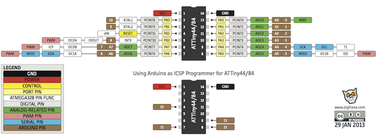
The pins I have available in the header are MOSI (PA6), MISO (PA5), and SCK (PA4). RST (PB3) is in principle also available, but as that pin also has other important functions, I’ll leave it alone for now. PA5 and PA6 double as PWM outputs, and they’re conveniently connected to LEDs on the bird-board, so I’ll use them as visual feedback to confirm that the strain-gauge reading program is working. That leaves PA4 (SCK) available to read the strain gauge signal.
The strain gauge set up I have dates from a bunch of years back, and was assembled as part of a laboratory exercise for first year mechanical engineering undergraduates. Two MicroMeasurements gauges (I’ll have to dig up the numbers later) are bonded to the top and bottom of a steel rule, which is mounted in a relatively robust wooden frame. The rule is fixed at one end and bent by turning a bolt mounted over the other.
[There will be a pic here soon]
I can’t remember off the top of my head whether there are two or four gauges in the set-up. If there are four, then the other two are mounted on a piece of steel that isn’t bent to serve as reference resistances. If there are only two, then there will be a pair of precision resistors available on the frame.
The strain gauges are arranged (either in a full or half) Wheatstone bridge as shown below. The two active gauges (R3 and R4) are wired in series on one arm of the bridge, while the two reference resistors (R1 and R2) are on the other. This way, when the beam is bent, and the resistance of one gauge increases while the other decreases, the potential difference is doubled in the middle of the arm relative to the unmoving opposite arm.
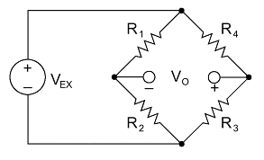
The change in voltage is calculated thus:
The resistors are typically 120Ω, and changes are of the order of 0.1%, so the δR on each gauge will be about 0.12Ω. The excitation voltage is 3.3V, so the expected δV will be 1.65mV. Obviously this isn’t going to be measurable on the pins of the ATtiny, so I’ll need to amplify the signal, which I’ll do with a simple op-amp on 1000 gain.
To confirm the whole set up is working, I’ll use the bird-board’s built in LEDs. The input from the strain gauge will override one of them, but the other two will turn on when the input voltage exceeds given thresholds and turn off again when the input goes cold.
Designing the amplifier board
This little board will need to do two things:
Provide regulated 3.3V power for the strain gauges Amplify the signal from the millivolt range to a volt range Filter out any really awful noise
Filter design
The measurements on this strain-gauge demonstrator device are very slow, quasi-static even. The main source of noise will be the mains (50Hz). Therefore I’ll need a low-pass filter with a cut-off frequency well below that. Rather arbitrarily, I’ll go with 20Hz.
A simple low-pass filter consists of a resistor and capacitor in series across the ouput of the measurement device. The signal is read after the resistor but before the capacitor. Wikipedia’s circuit diagram is nice and clear:

The choice of components is determined by the mathematics of the filter. The cutoff frequency (in Hz) for such a filter is given by:
Resistors are easy to find, so we’ll start with the capacitor. In the standard fab inventory, a 1μF cap is easy to come by. To make a nearly 20Hz filter, then the resistance is calculated as follows:
I can’t remember whether we have 8kΩ resistors in the standard fab library, but I know we have 10kΩ ones. The cutoff frequency with 1μF and 10kΩ would be:
which would also be fine. So I’ll select the components when I get to the lab on Monday.
For those too busy to pick up a calculator, there’s a useful little design tool on the web here to determine the values of the filter components.
Amplifier design
Operational amplifiers are delightfully easy to use. In the non-inverting set up, the op amp is connected directly into the signal line, with a pair of resistors across the negative side, which determine the overall gain. In this case, since we are dealing with a low current system, there will be no need to AC couple the amplifier. So the circuit diagram is simple:
The gain of this circuit is given by:
The requirement here is for 1000 gain, so if R2 is 100kΩ, then R1 can be 10Ω. Both of these resistors are available in the standard inventory.
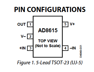
The standard op amp available in the fab inventory is the AD8615. This is a single circuit op amp with what look like appropriate characteristics for the application here. The datasheet is available here. Ours is the TSOT-23 version, shown below.
Power supply
The strain gauges need a 3.3V supply. This can be delivered by one of the standard fab lab voltage regulators, namely the LM3480IM3-3.3. According to the datasheet, the 3.3V version of this voltage regulator is designed for a 5V input, presumably specifically so that it will suit the kinds of USB-driven circuitry we’re building. The datasheet also recommends that the voltage regulator be equipped with a pair of capacitors to smoothe out its signal, as shown in the excerpt below:
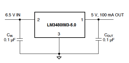
No specific mention is made in the datasheet about the specification of the capacitors for the 3.3V version, so I’ll just go with the same ones they recommend for the 5V version.
PCB design
Now to fire up Eagle
The circuit design is straightforward. Really just a question of using the elements out of the fab library. I’ve used a single ten-pin connector block. There are three different ground pins for the moment, since there will be different peripherals connecting, each of which will need a ground of its own.
The board layout went together relatively straightforwardly. Only needed one zero Ohm resistor to jump a net. I used the ULP cmd-change-brd-width to change the trace thicknesses all to 30MIL. Some of the traces now look too thick - I’ll check before milling. There was also some discussion on the voltage regulator datasheet about making the pads bigger to dissipate heat.
A professionally designed version
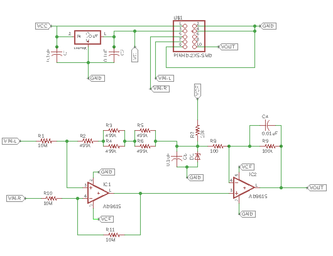
Apparently I’ve overlooked a few things in my simple design. Below is a professional strain gauge amplifier circuit from Analog Devices.
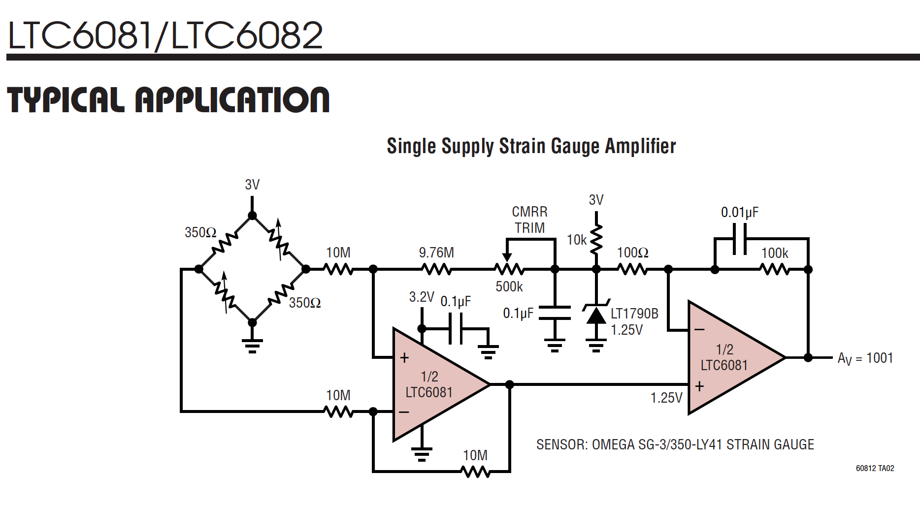
The core of the amplifier is similar to what I designed, namely the right-hand opamp with its 100kΩ/100Ω ratio. The additional capacitor in that stage is presumably acting as a noise filter. The zener diode is providing a stable reference voltage above the ground rail, so that the amplifier can swing negative when the bridge goes that way. They’ve added a tunable low-pass filter before the zener, presumably to cancel out any noise on the unamplified side of the signal pair. The left hand amplifier is a simple follower, included to increase the input impedence of the circuit and therefore avoid any back current into the bridge which would influence the measurement. They’ve also included a capacitor on the VCC into the amplifier, to reduce any effect of regulator wobble.
I like the look of this board, with its extra elements to reduce the noise, so it’s back to the Eagle drawing board. I don’t have an LTC6081 in the fab inventory, so instead I’ll use two AD8615’s. My board will also include the power supply, which theirs simply assumes. Because I don’t have a suitable 500k potentiometer available for the filter, I’ll just use a pair of 499kΩ resistors to set the value halfway. Finally, because my regulator already has a capacitor built into it, I’ll leave out the extra one on the Vcc line.
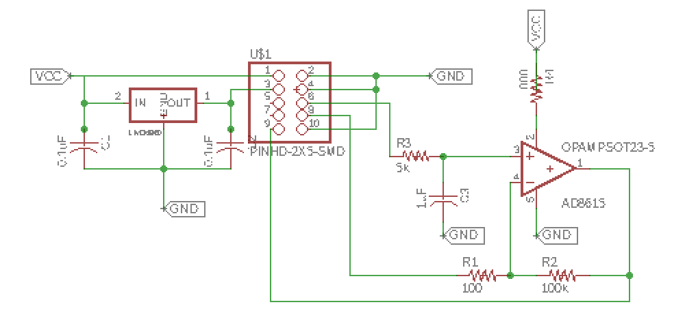
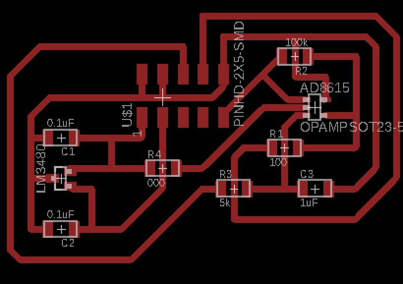
The final circuit and PCB end up looking like this:
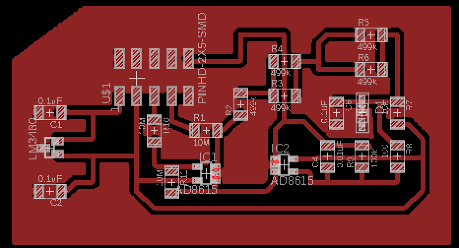
Here I’ve also worked out how to set up the trace widths and spacing. The clearance around the traces is set in the Edit:Design Rules dialog box, in the Clearance tab.
![]()
Once the settings are enterred, then use the rats nest button to apply them in the board design. A clearance of 30mil seems to work ok.
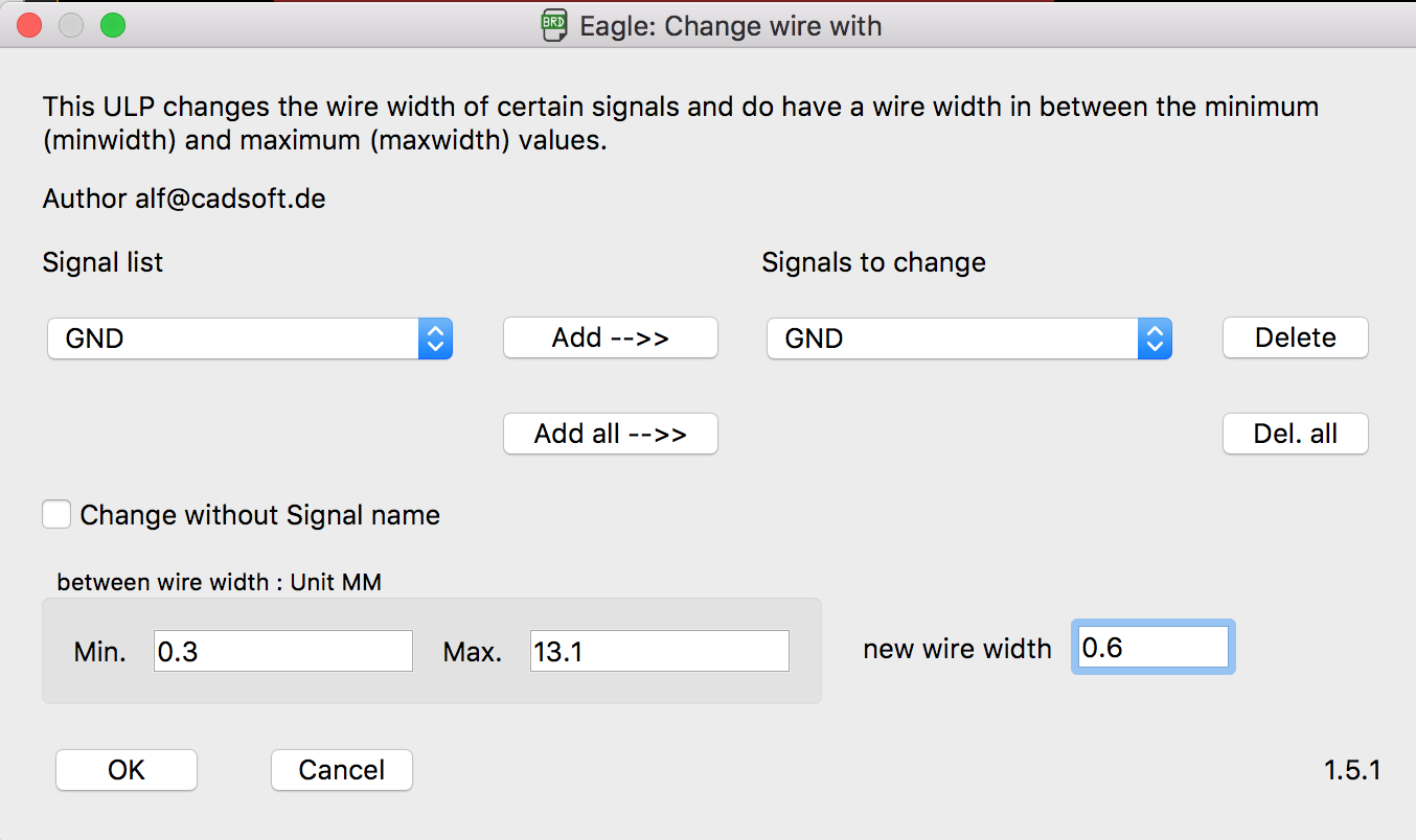
The width of the traces is set in the ULP cmd-change-brd-wdith, whose dialog box is called “Change wire with” (sic). Add all signals to the list, then set the Min wire width to something like 0.5mm-0.7mm and the between wire width to 0.3mm.
Reality resists…
Further revision of the circuit has become necessary, now that I’ve returned to the FabLab and learned what resistors we really have to hand… The new design looks like this.
Manufacture
I never did get around to manufacturing this board last year. It seems a shame not to do it now, though, so I’ll give it a go in the next few weeks.
Testing
We’ll see how this goes.
Connecting to the Bird Board
This should be fairly straightforward.
Programming
As this week’s focus is on input devices, there won’t be much programming involved, except to detect that the signal has been received and provide some visual LED feedback that there has been some input. I’ll use the LEDs on the bird board for this purpose.
Pressure Gauge Reader
This will be a whole new device.
Oh by the way…
Math on this page is rendered using the CodeCogs Editor using the embed codes as described at StackOverflow.