8. Computer controlled machining
The CNC Machine
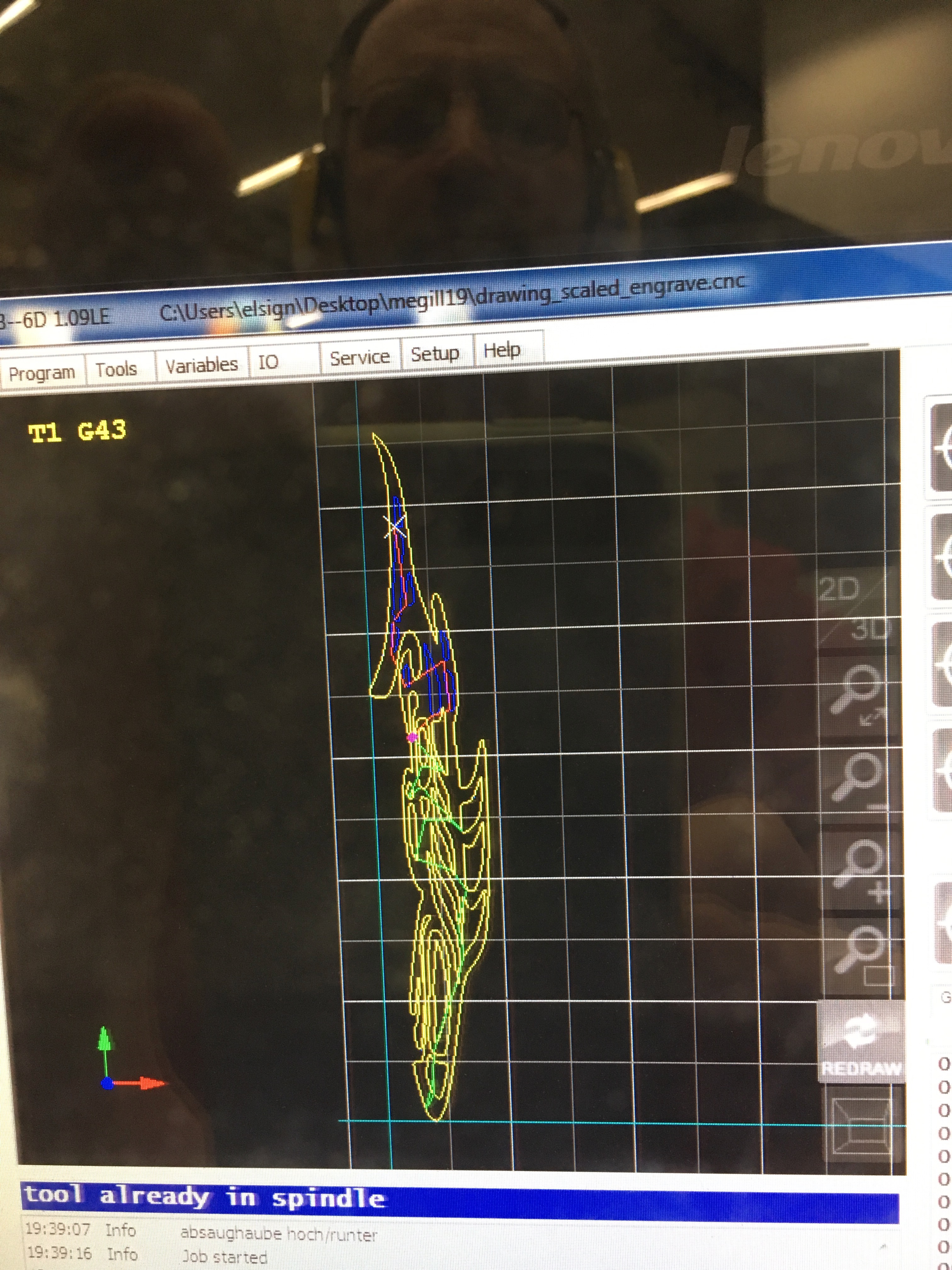
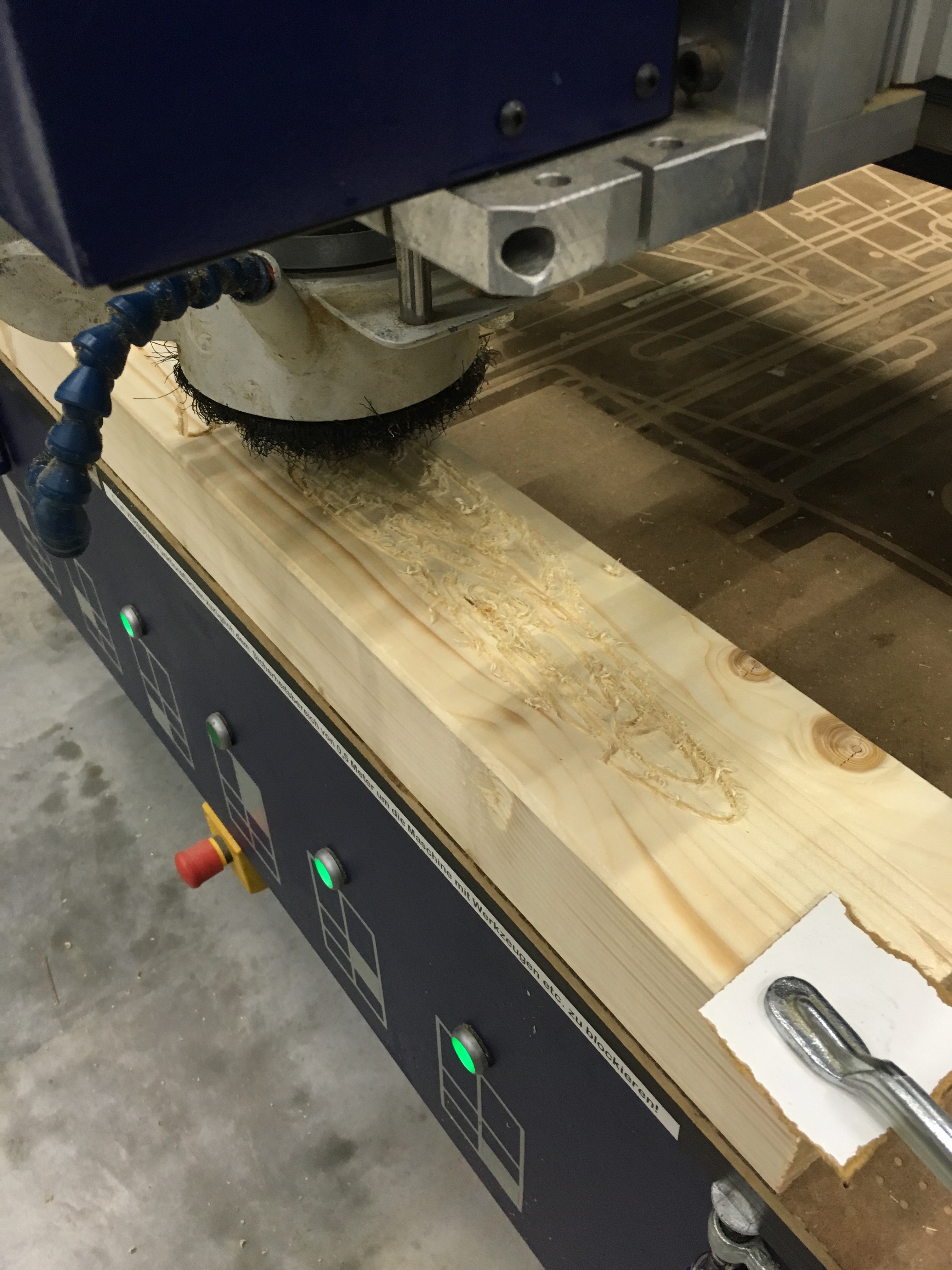
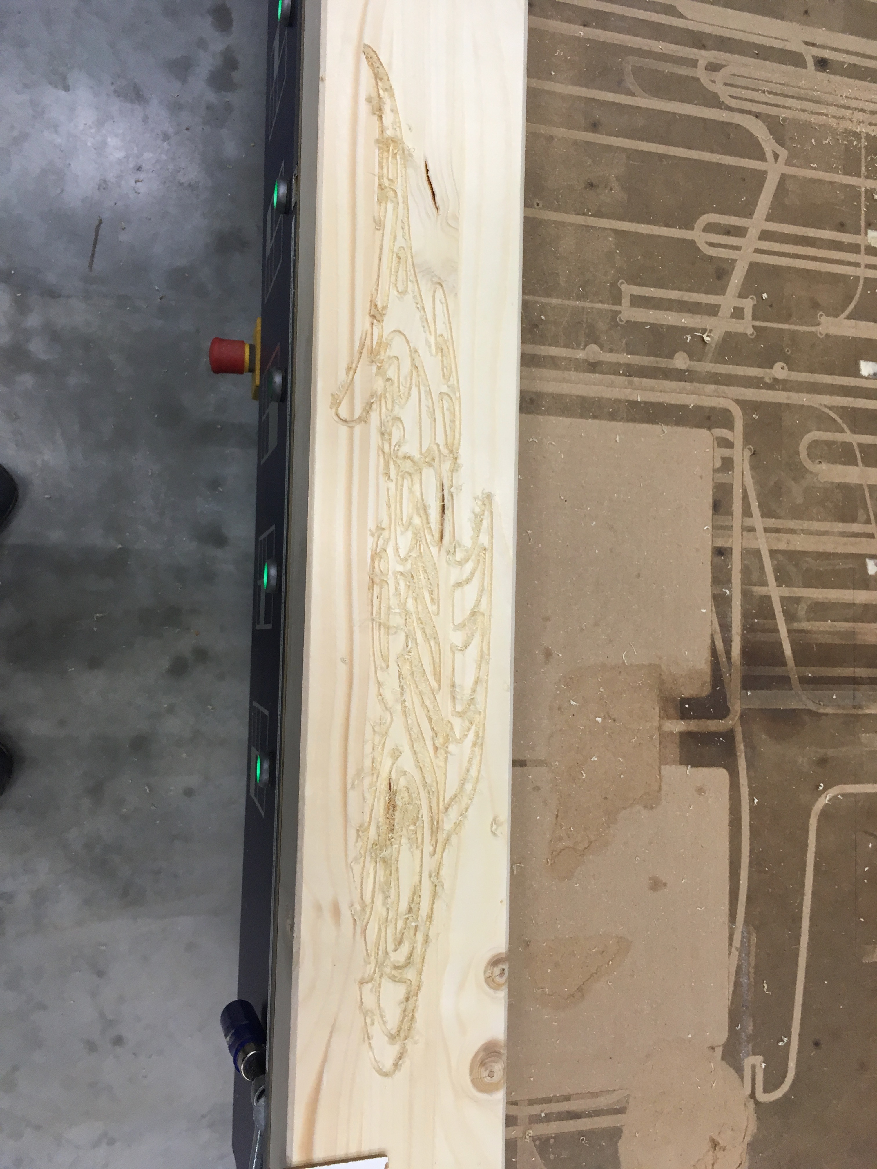
Engraving

Making something big
Last year I made a plywood bracket to hang one of the lab’s submarines from the wall. This year, I’ll make the second bracket, incorporating some of the lessons I learned last year. I’ll also make a cart for transporting small scuba cylinders - a task imposed upon me by a recent safety inspection of my lab that didn’t go as well as I might have liked…
A bracket for the Submarine Museum
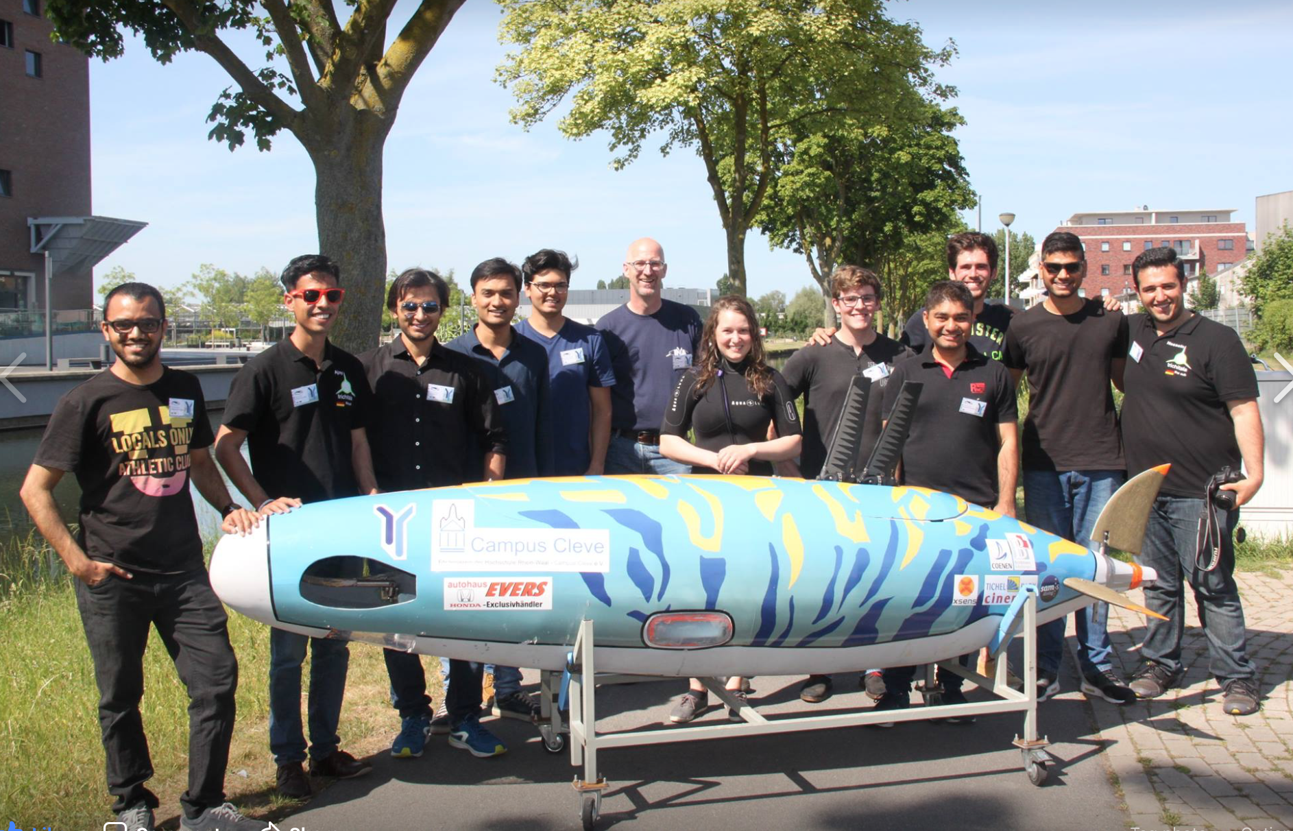
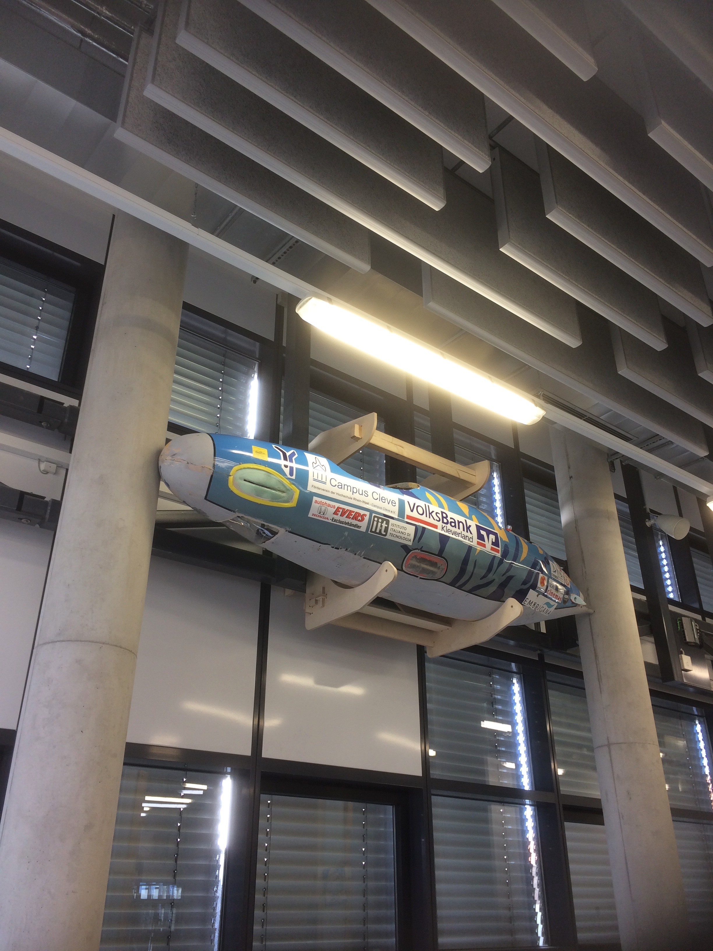
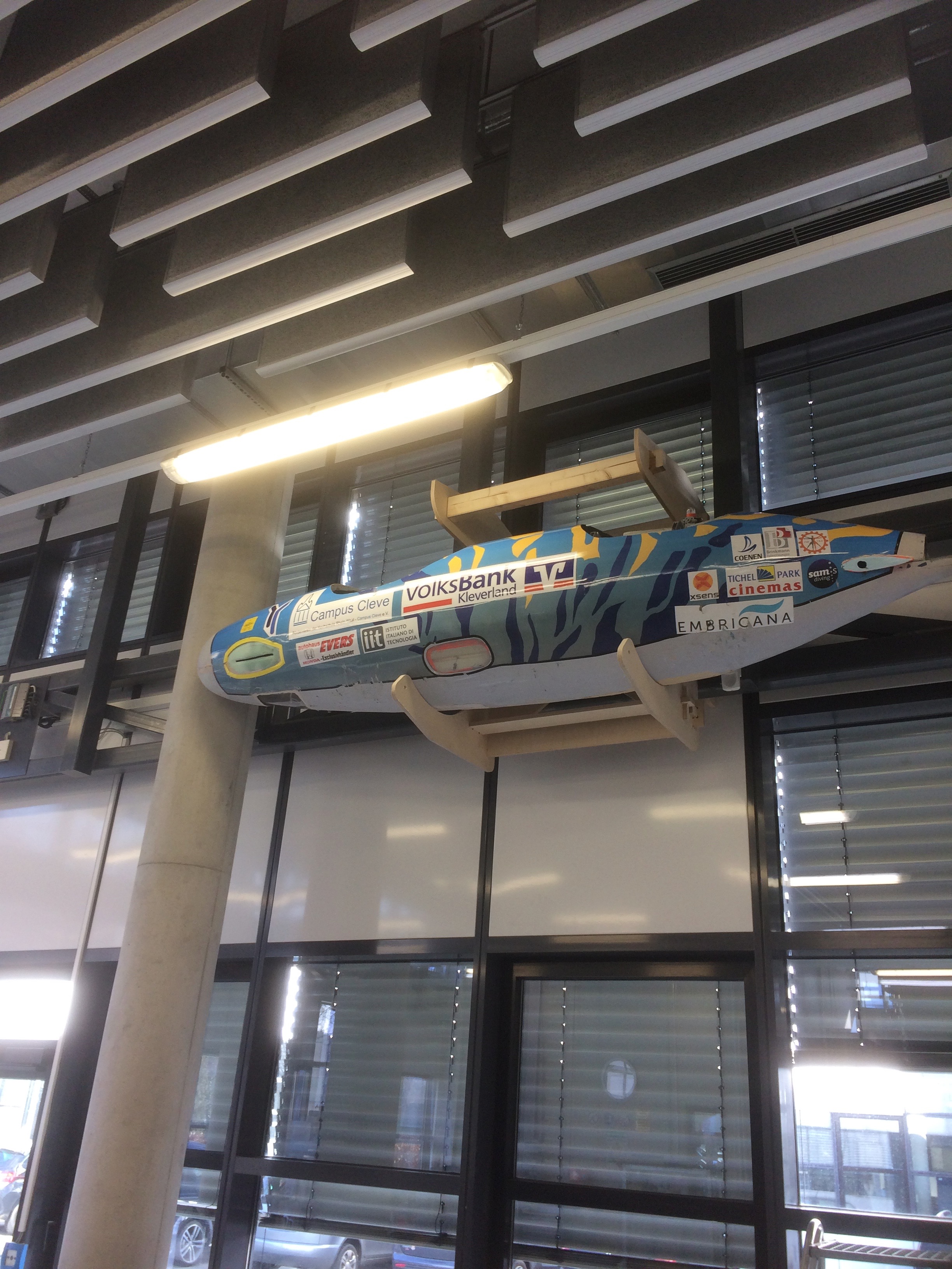
My students take part every year in a human-powered submarine race, either in Washington DC (odd numbered years) or in Gosport England (even numbered years). The submarines they build are about 3m long by about 70-80cm in diameter.
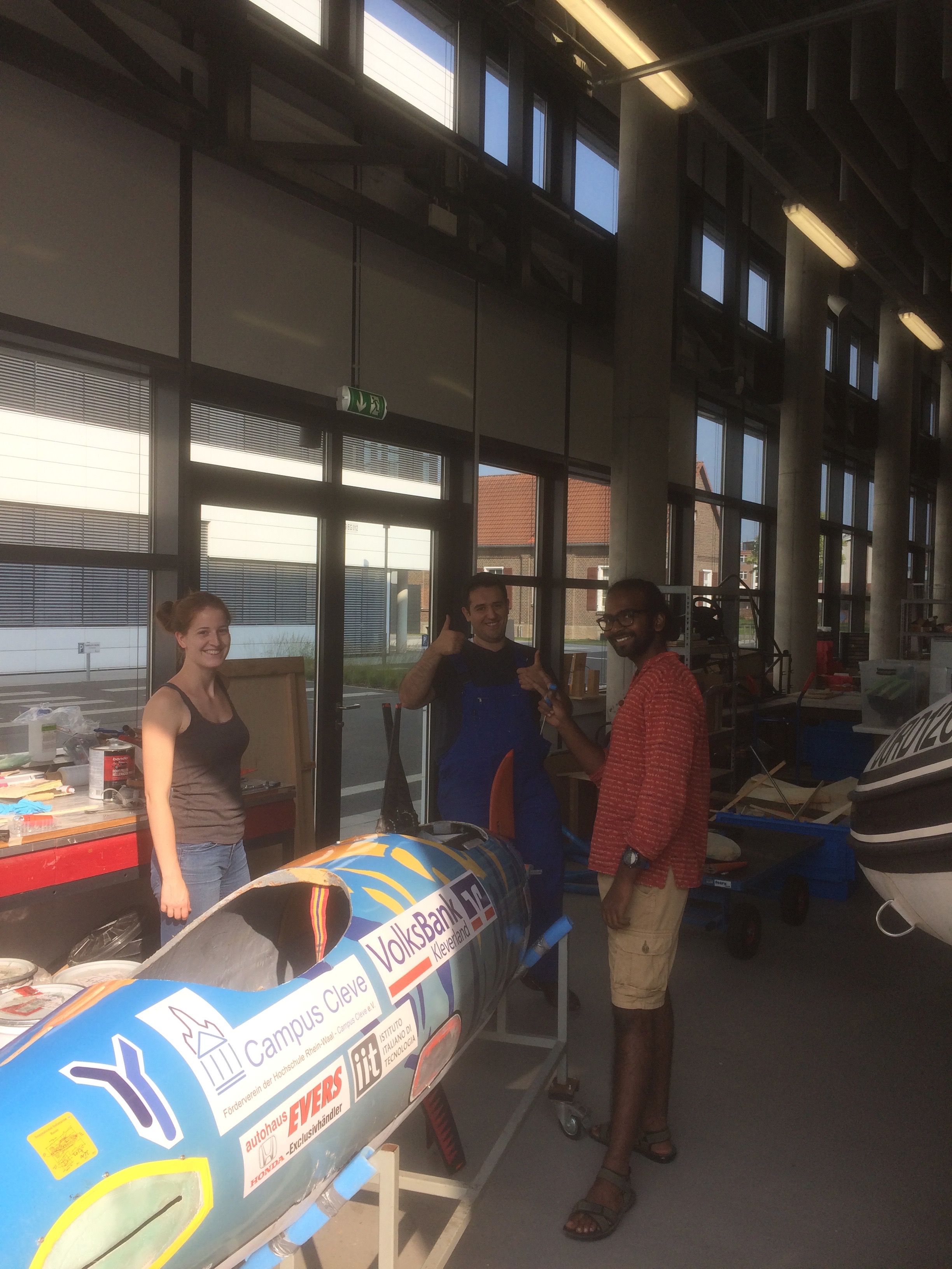
Even though they’re on wheels, they do take up a lot of room in the lab, and so a clever storage space is needed. The girders along the outer walls of the lab (seen above the students’ heads and below the upper windows in the pic below) seem like they were designed to have submarines hung from them.
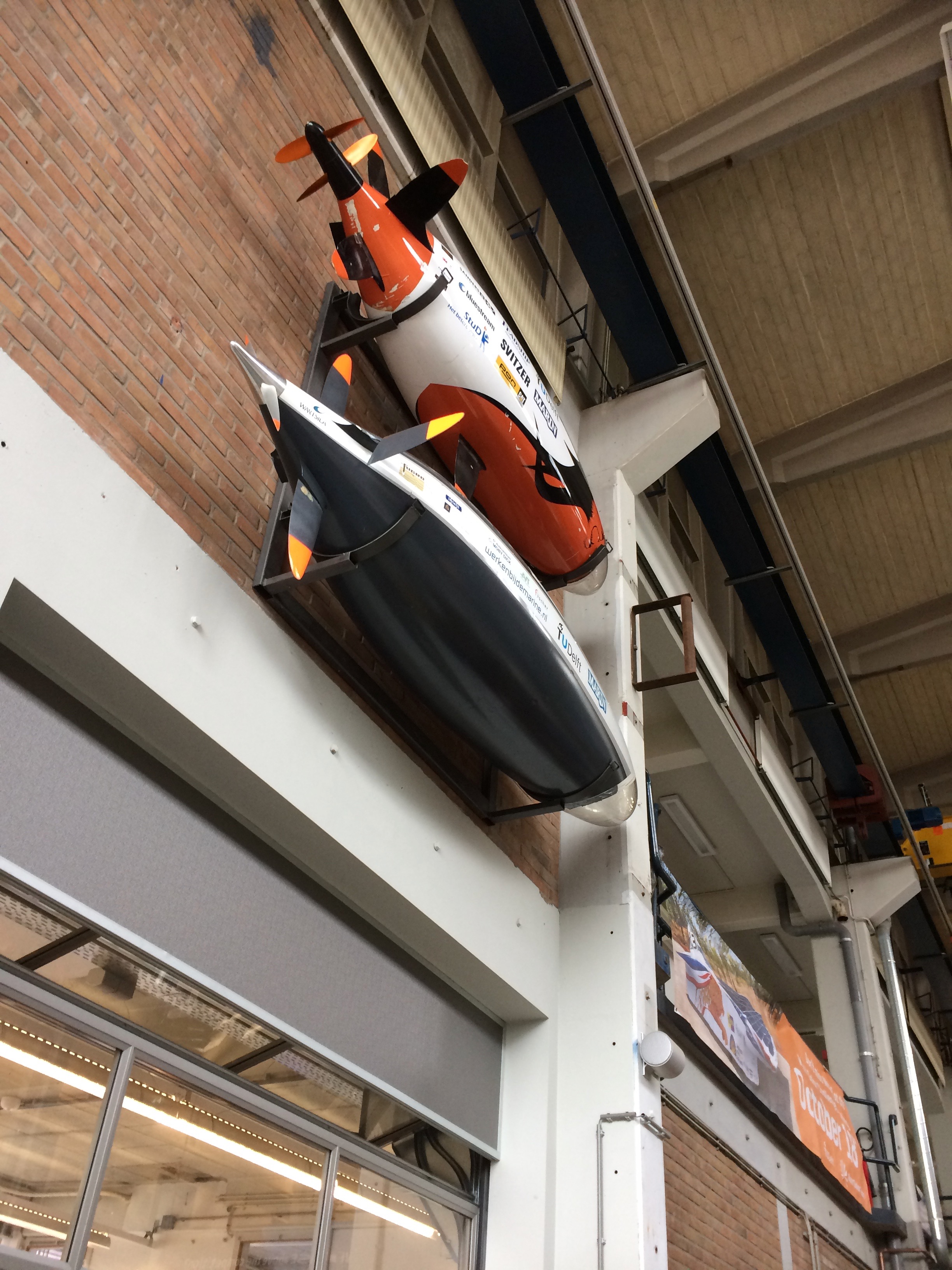
The idea came from a similar set-up I saw at the TU Delft, where they’d hung two of their submarines on a wall over their workspace. The submarines weigh about 75kg when empty.
Design
I was going to make the frames out of steel as Delft had, but taking this class has reawakened the carpenter in me, so here goes with a design made out of plywood. The first draft (in steel) was drawn up in OpenSCAD, using some parametric structure so that I could easily adjust the spacing.
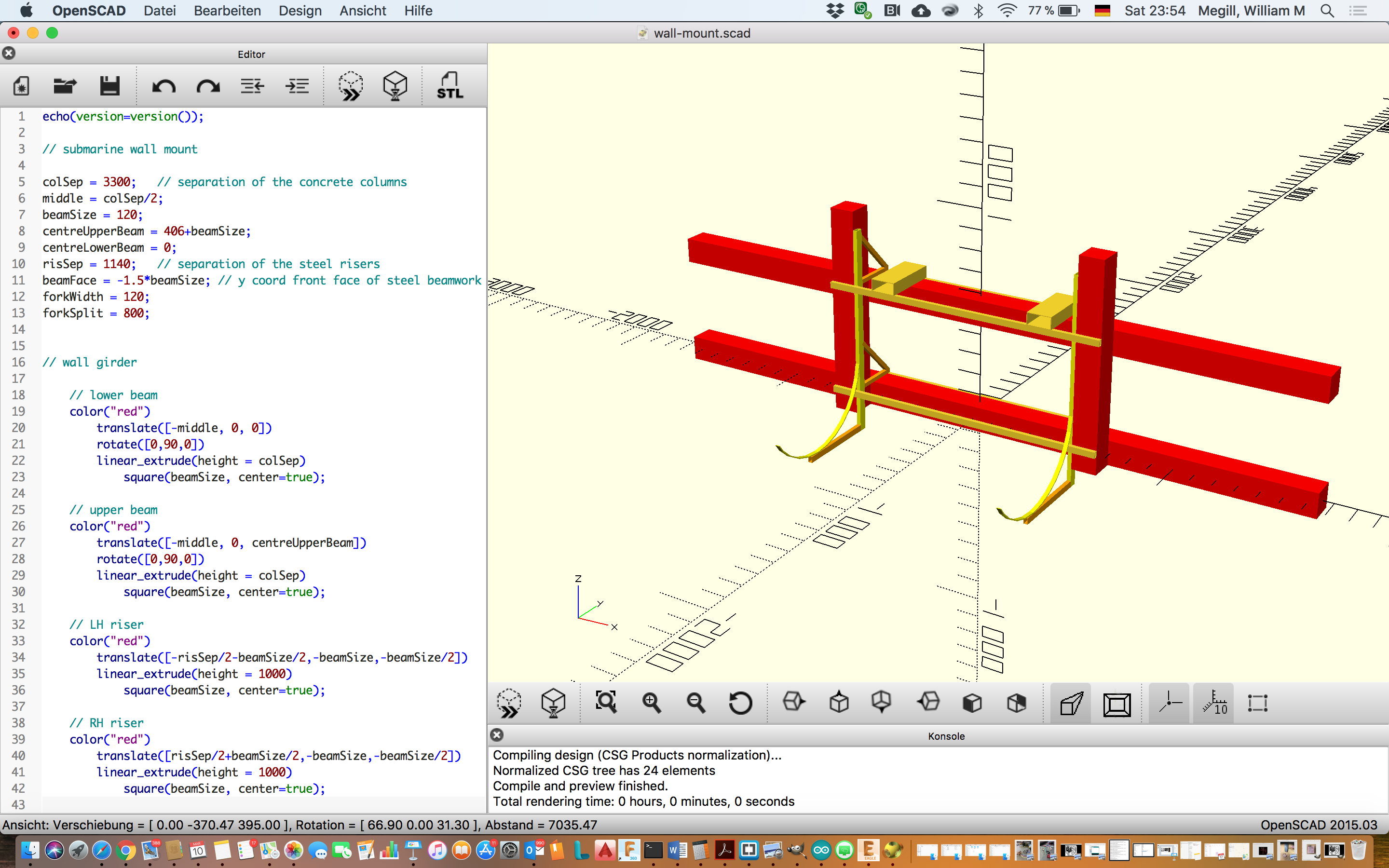
OpenSCAD works well for simple shapes, but for the kind of organic looking shape I wanted to do on the CNC mill, it didn’t make sense to fight through the mathematical representation, so I turned to SolidWorks instead. The final design looks like this:
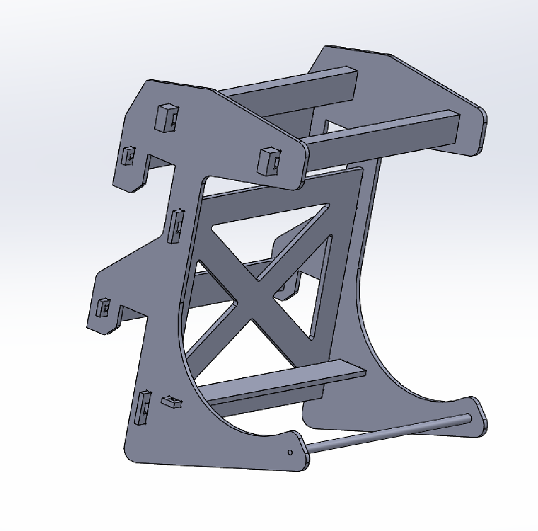
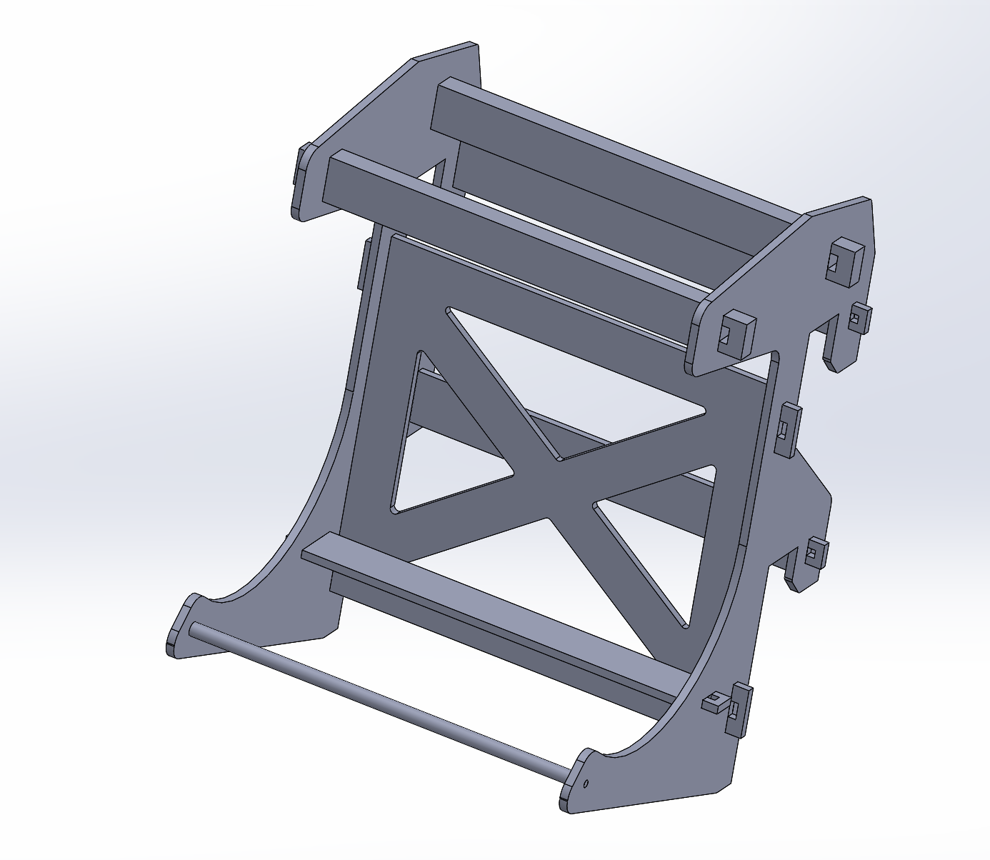
The design consists basically of two brackets which support the submarine on the one side, and hang snugly off the girders on the other. The cradles are curved under the submarine, with a raised lip on the outer edge to ensure that the sub doesn’t slip out during lifting or lowering (or indeed in during the time it’s on display). The back side of the brackets consists of two open square slots which fit snugly over the girders such that the weight of the submarine and frame is distributed over the tops of the two girders. The centre of mass will be out over the cradles, so the hanger will tend to rotate around the upper girder. The vertical side of the the bracket will stop that motion. I had some welcome feedback from my instructor about the width of the central riser section of the bracket, which I incorporated into the final design, shown on the right. I also shortened the bracket a bit vertically so that I could fit two of them on a 2,5m long plywood board.
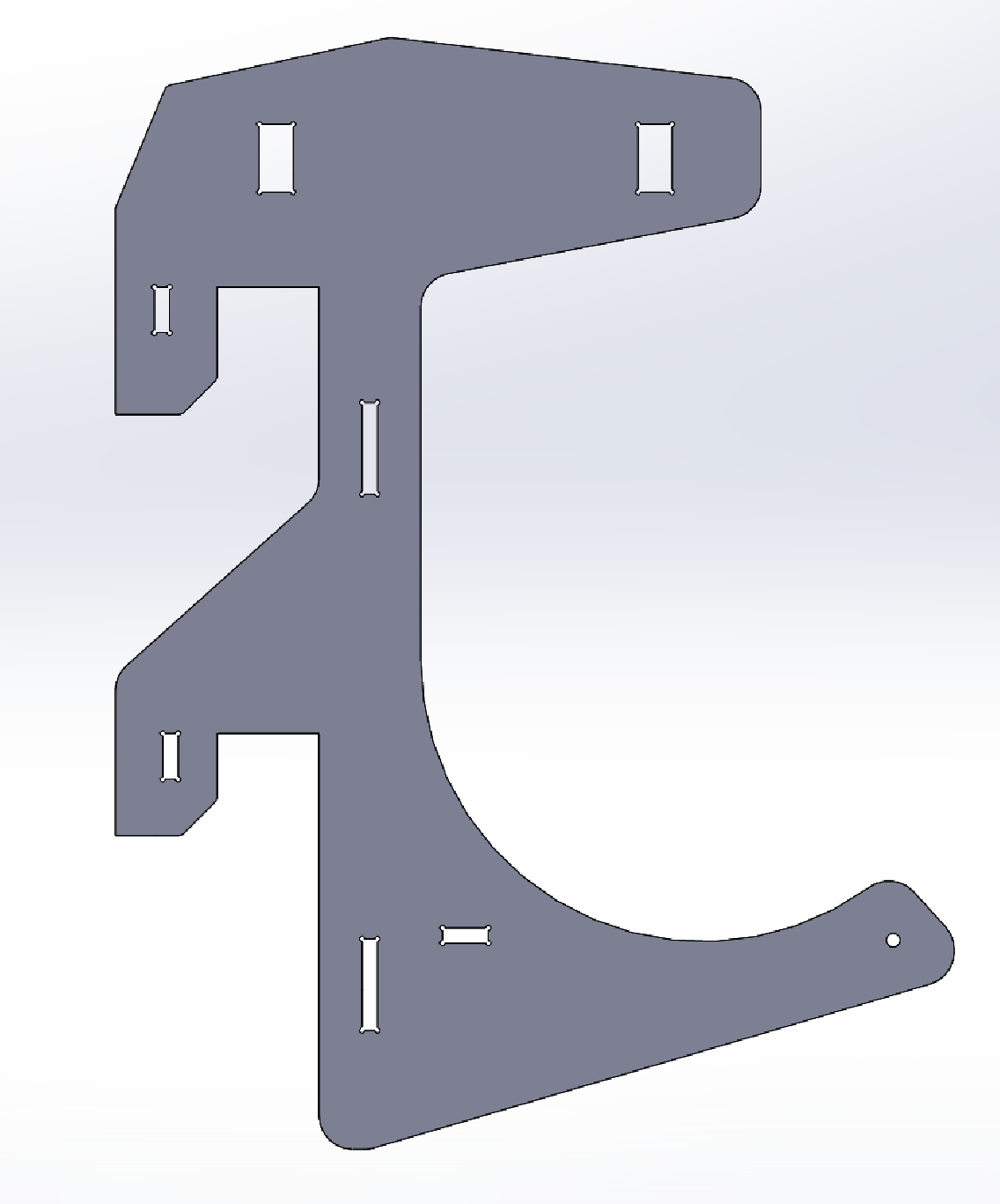

Rigidity of the frame is assured through the crossed members of the back panel. The whole panel is cut from a single sheet of plywood, which results in an even distribution of the loads. The back panel is attached to the brackets through the use of slots with keys.

Additional torque resistance is provided by the three smaller braces. These are also connected to the brackets using slots and keys. Note the 6mm diamter circular cutouts in the corners of all of the square holes. These are there to allow the tool some room to manoeuvre as it machines out the slot.

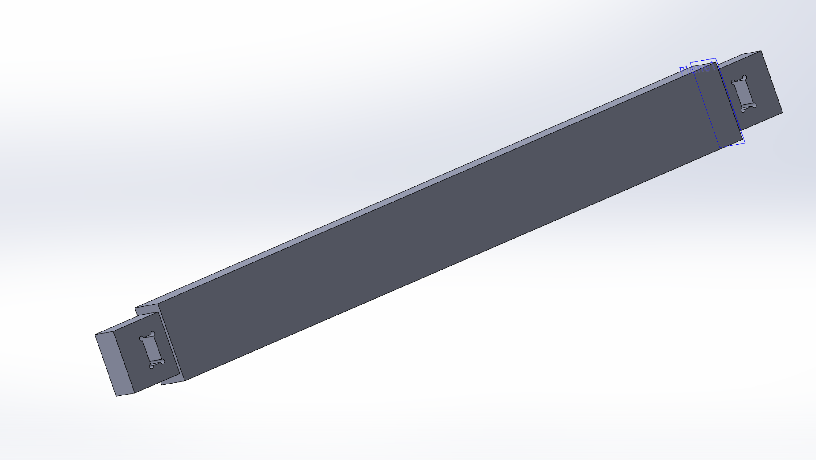
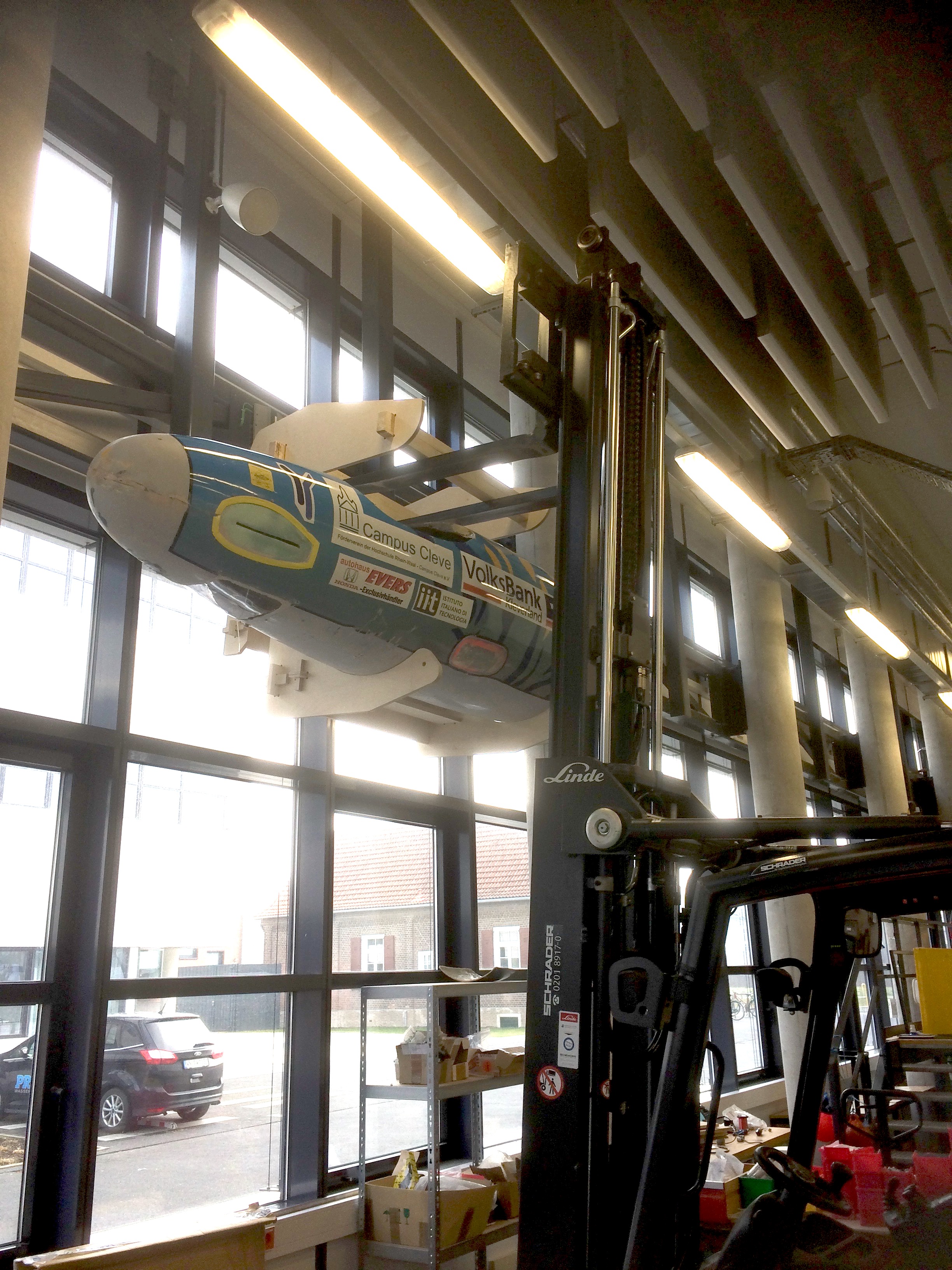
The hanger is designed to be lifted up or down from the girders using the university’s forklift truck. The overall combined weight of the unladen submarine and wooden frame will be about 85kg. This load is easily supported by two 2x4” beams. The forklift’s tines are usually set at 80cm separation distance. The frame is 89cm wide between the brackets, ensuring that the forks are very near (without touching) the brackets, in order to minimise the bending load on the beams. The beams are furthermore connected to the brackets using the slot and key design incorporated for the other elements above. In order to distribute the load more evenly over the 2x4” beam, the ends are milled symmetrically, which required a few extra passes with the mill and some careful alignment of the workpiece during set up.
The last piece is a dowel for the lower front side. Mostly this part is cosmetic, and serves as a place to hang a sign from, but it also plays a minor role in ensuring that the cantilevered lower braces don’t splay apart. During lifting and lowering, the dowel will also serve as a place for fastening straps to keep the submarine in place.
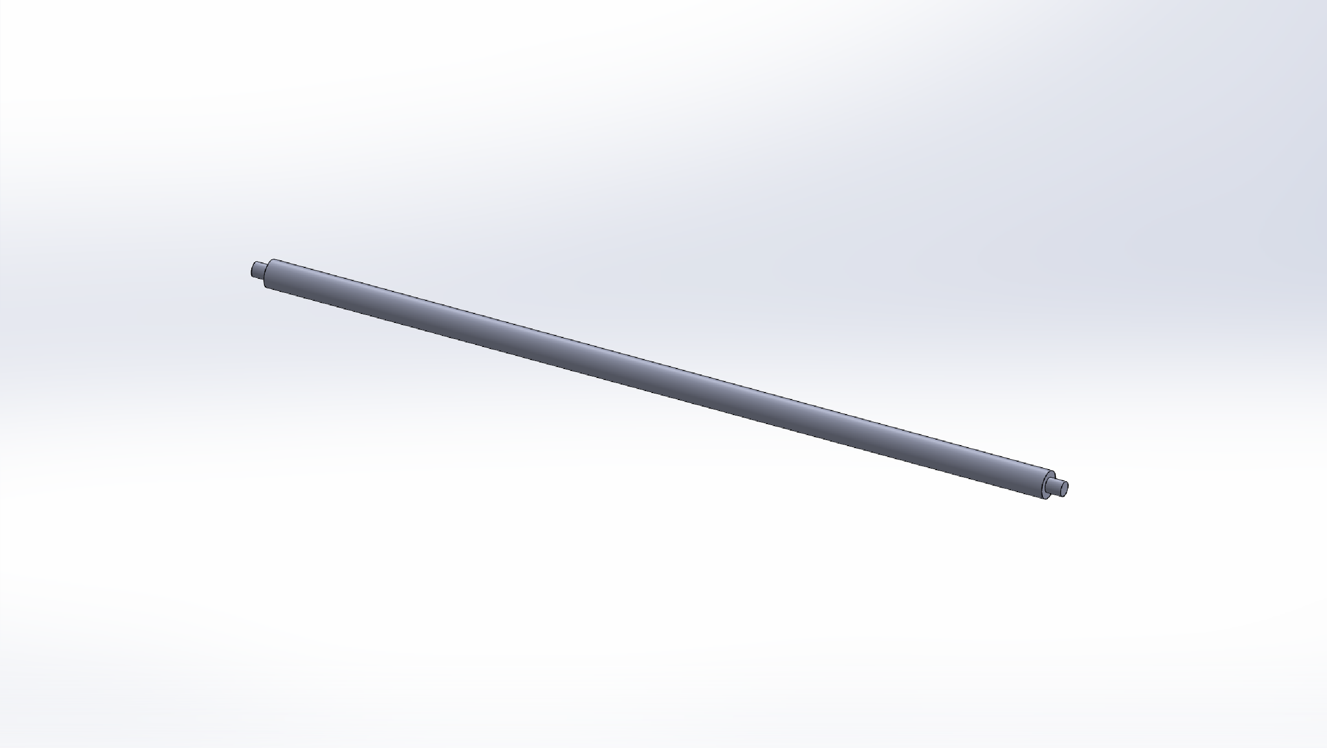
We don’t have a CNC lathe available in the FabLab, so I had to make this piece by hand on the manual lathe in my workshop. I didn’t have a wooden dowel available, so I used a bar of PVC instead.
Manufacture
Well that was frustrating. Wow. A whole day to do what should have taken a few hours. All because of an obscure bug in a commercial software package. Ugh.
The steps were relatively clear and straightforward:
- Export the files from SolidWorks in 2D dxf format
- Import the DXF files into Rhino
- Select and "join" the curves
- Arrange the various parts to be cut to make best use of the plywood sheet
- Split the small internal cuts and large external ones onto separate layers.
- Export the file from Rhino as DXF using the "R12 Lines & Arcs" option
- Import into the CNC program on the mill control computer
- Cut out the internal layer as described in the CNC section above
- Cut out the external layer
- Remove the finished parts from the mill
- Clean up and go for lunch
Dinner came and went.
It was only after the pizza had landed face down on the floor and been consequently binned that the software bug finally presented itself. Somewhere in Rhino, something gets corrupted, and the DXF export function generates erroneous code. Curves are separated and segments are scattered seemingly randomly around the screen when the file is loaded in the CNC control program.
The workaround is apparently simple:
- Complete all steps above to #5, then:
- Select all and copy
- Open a new instance of Rhino
- Paste the parts into the new instance.
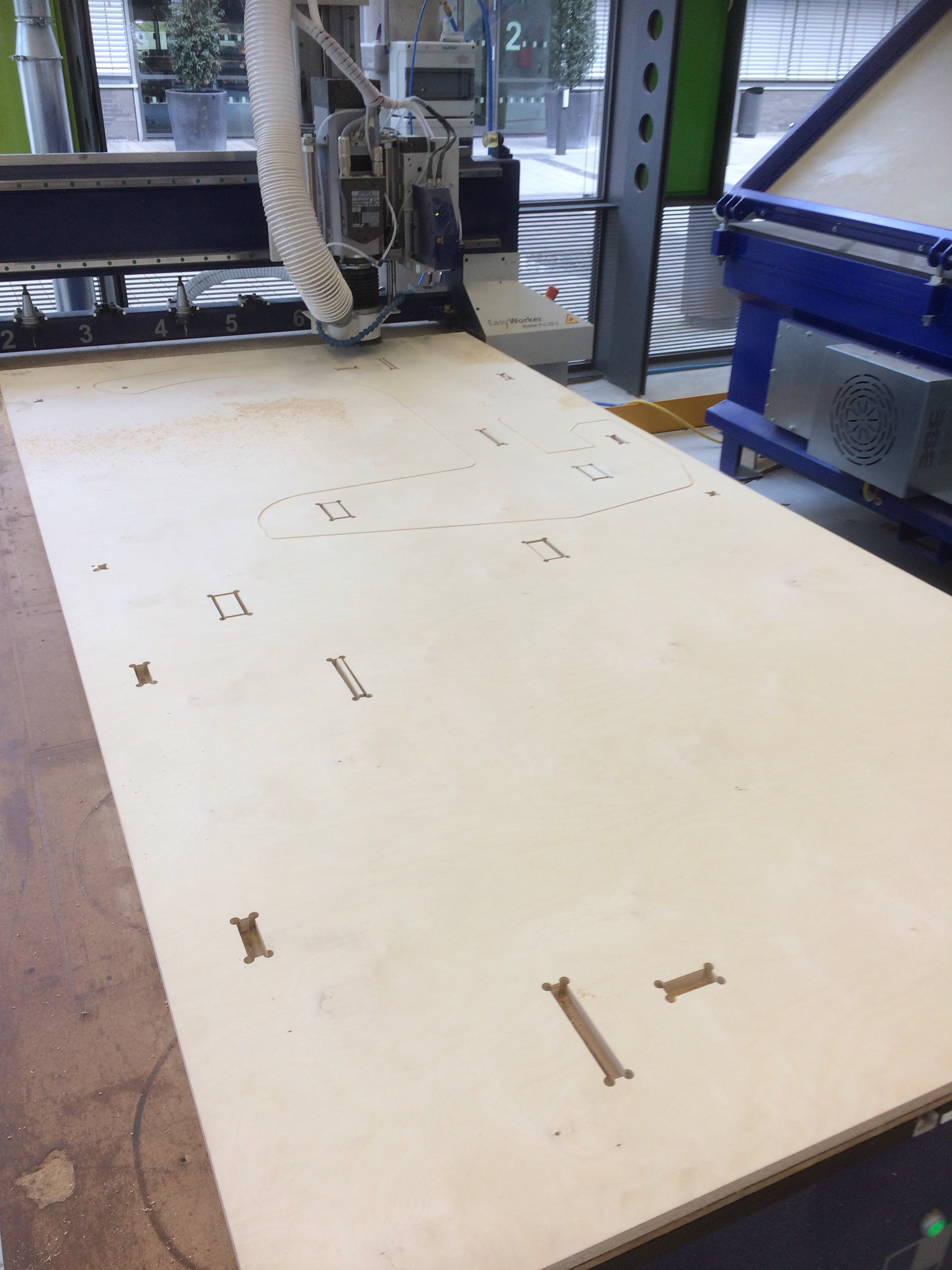
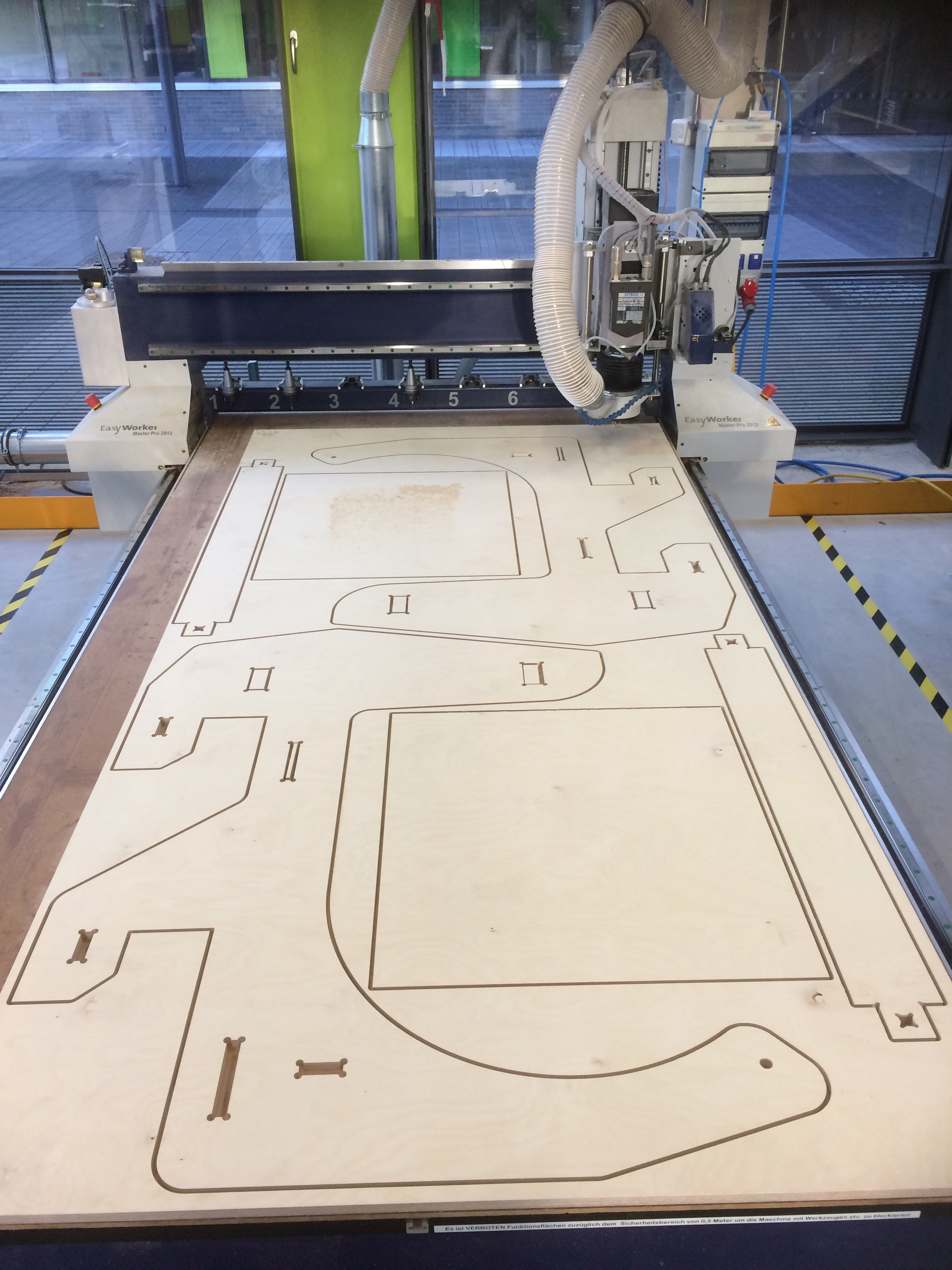
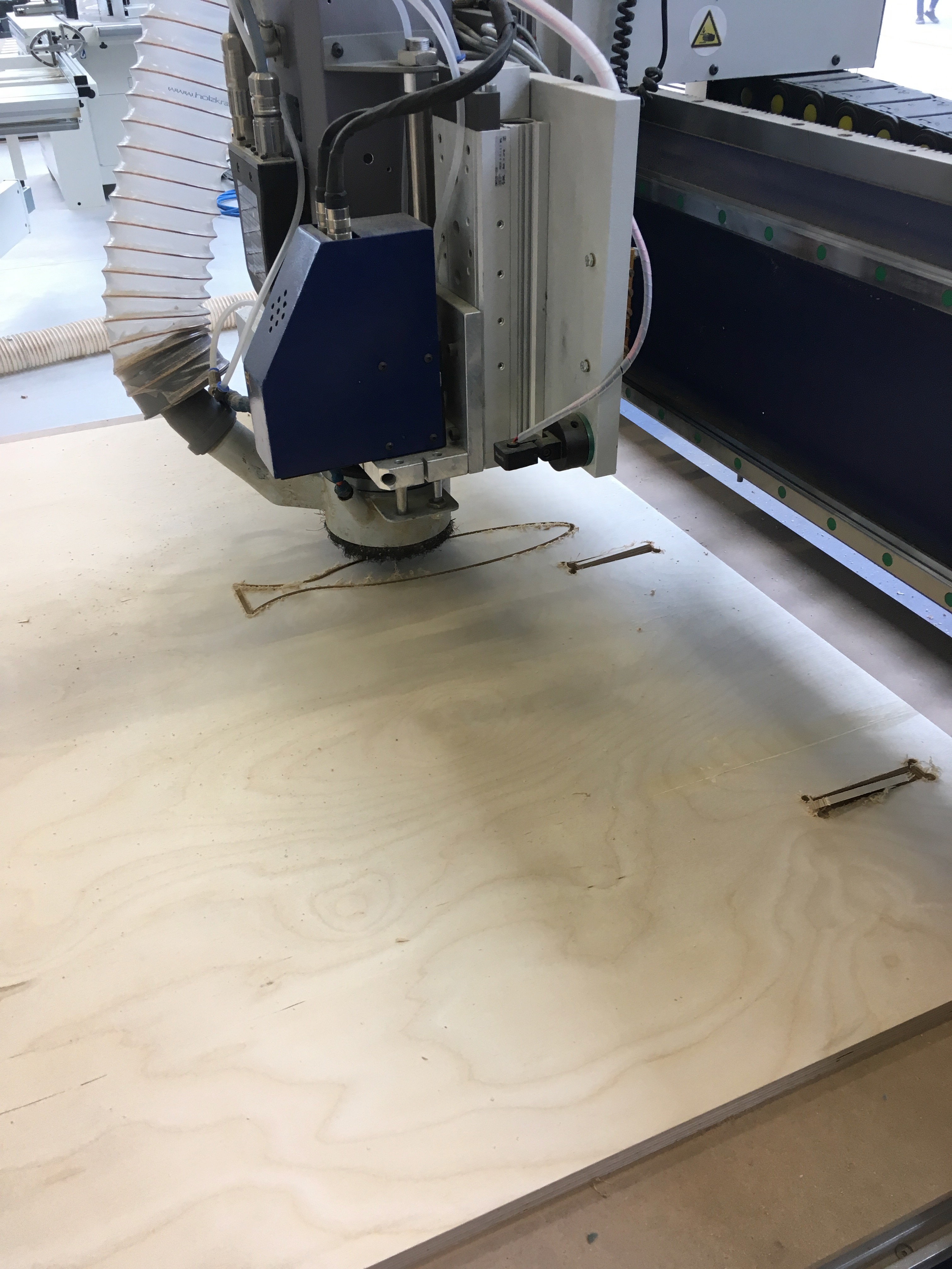
Once I added those steps into the process, the whole thing worked like a charm, and I could start cutting the shapes out of the 1,25 x 2,5 m bit of 18mm thick plywood board I was provided. Cutting started with the small inclusions:
… and finished two hours later with fully cut out parts, ready for assembly.
The process was repeated with a second board. Parts here were the back of the frame, one more stringer and the locking pegs. To ensure that these latter parts didn’t fly around during manufacture, the external cuts were stopped 1mm from the table, and when the machine had finished the cutting pattern, we taped up the top of the little blocks with masking tape, then ran the cutting pattern again to cut through the tape and the leftover plywood at the bottom of each cut.
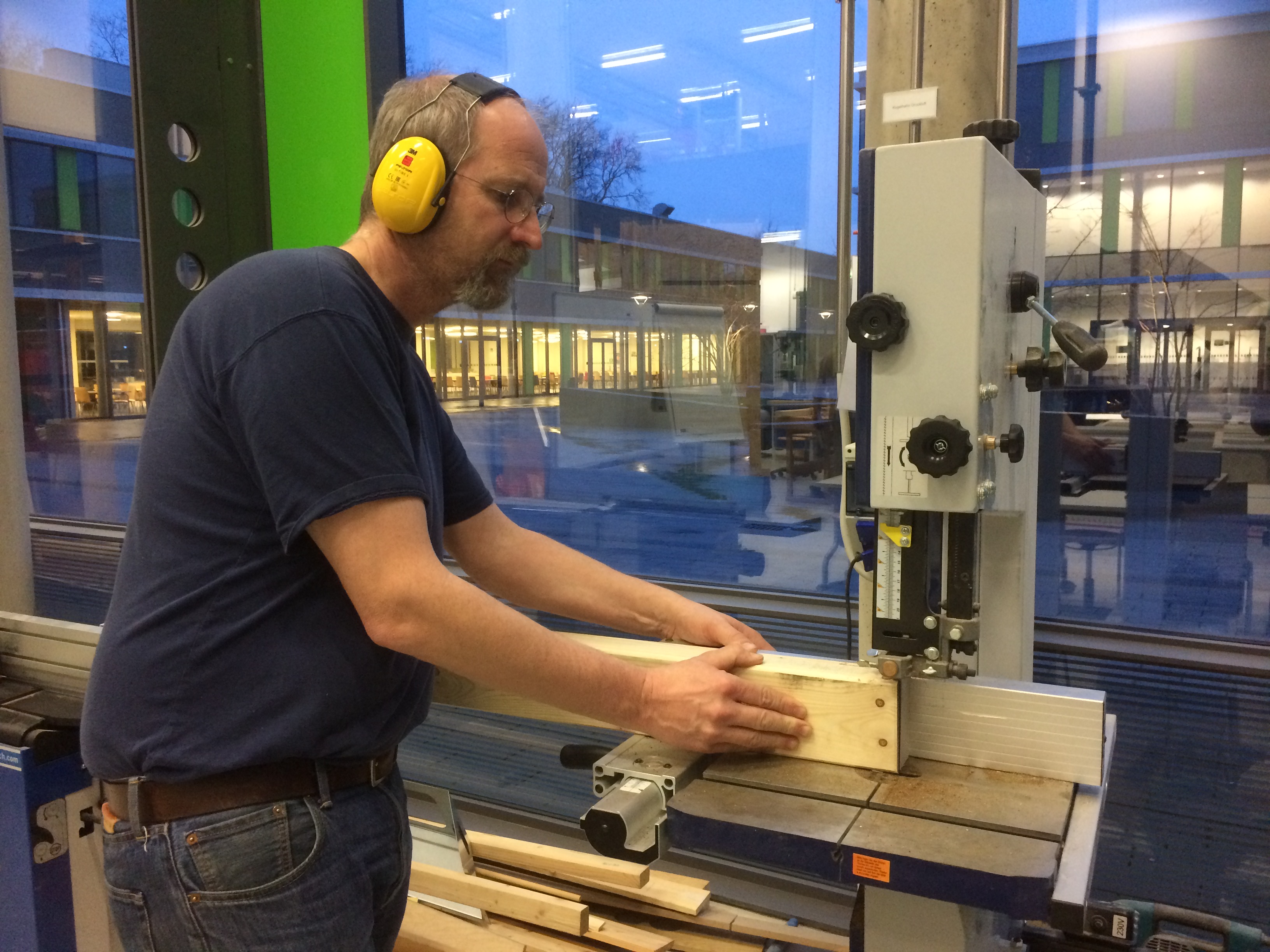
The final manufacturing step was to make the two top beams. I decided not to use plywood for these, as I was worried about delamination, since the beams are to be loaded on the thin side, and will have to take repeated hits from a forklift truck’s tines. I opted instead for a pair of trusty 2x4’s. They don’t make 2” x 4” cuts in Germany, so a 6cm x 10cm bit of pine was purchased instead.
There are times when automation just isn’t up to the task. It proved impracticable to clamp the slightly warped 2x4 to the mill bed (even screws wouldn’t have solved the problem, as the warp would simply have bent the MDF bed). So instead, I dusted off my old wood shop skills and fired up the band saw. Four cuts at each end (on a really dodgy band saw), and voila.
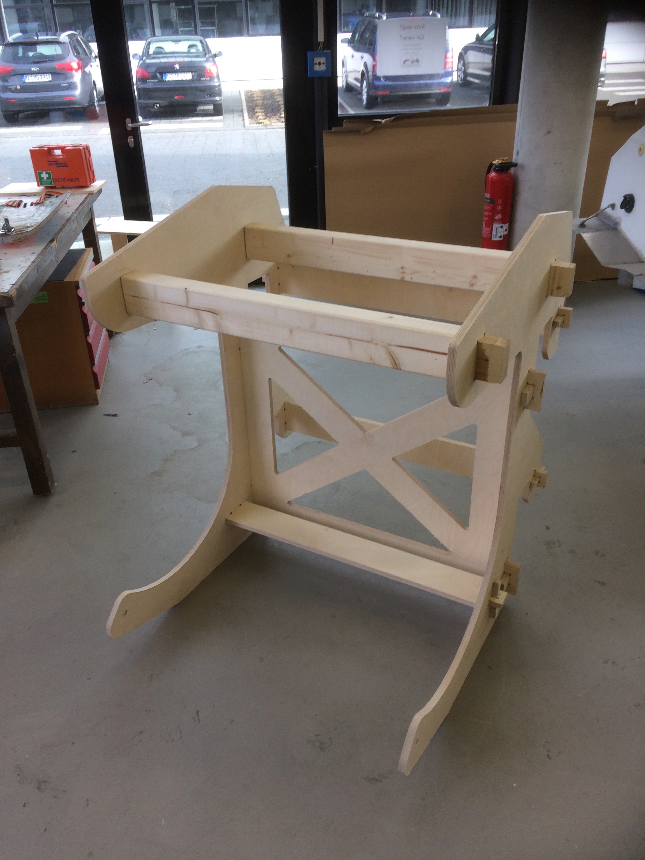
Assembly
Assembly was straightforward. Some quick work with a hammer, and a few additional fillet cuts with the bandsaw put the whole thing together nicely. Some of the fits were pretty tight, so I used a spare bit of 2x4 as a stress distributor when hammering. Also the plywood tended to lift around some of the joints as the perpendicular piece moved through, so I use the block to hammer directly on the lifting parts, which put them back into place.
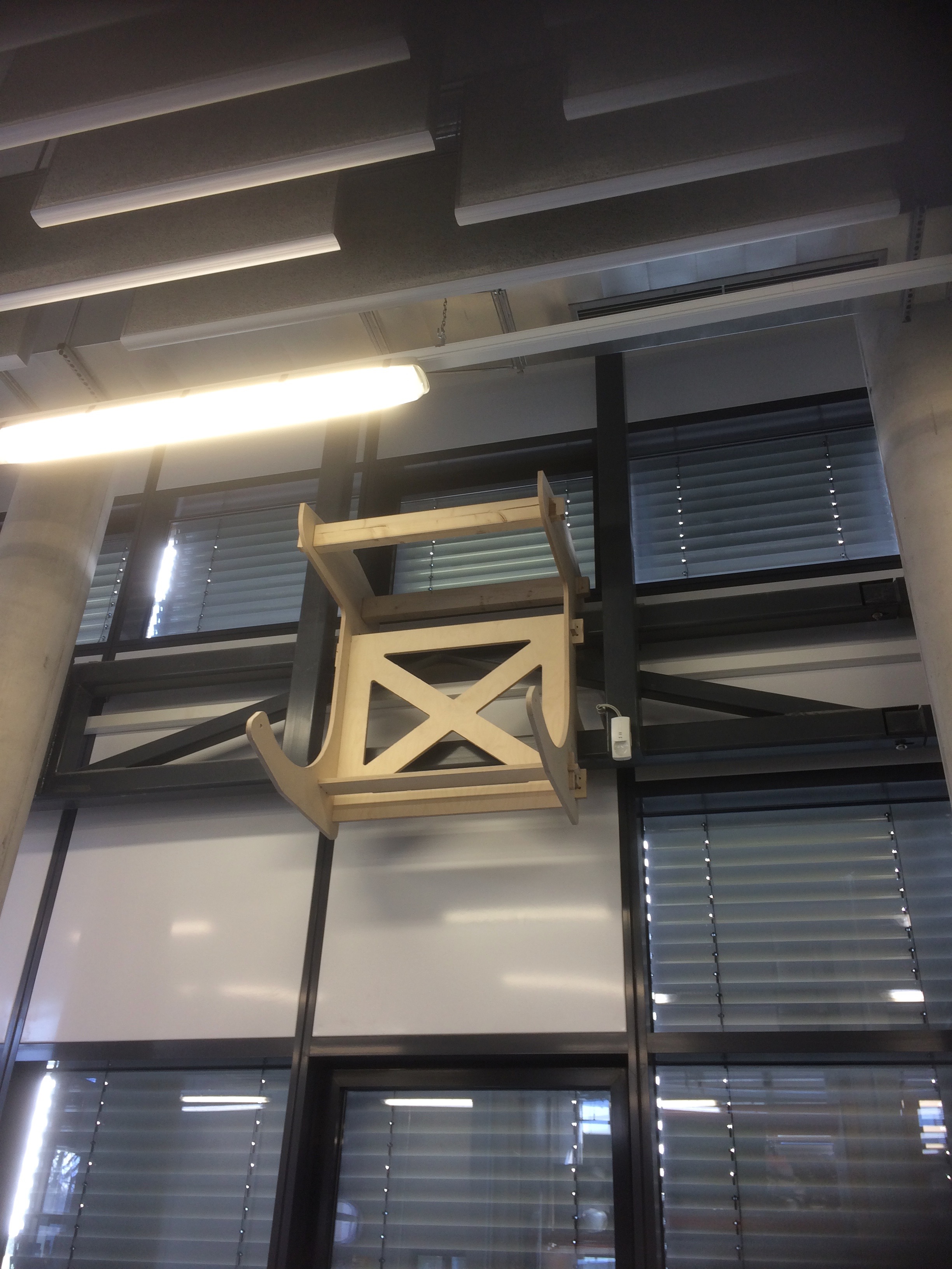
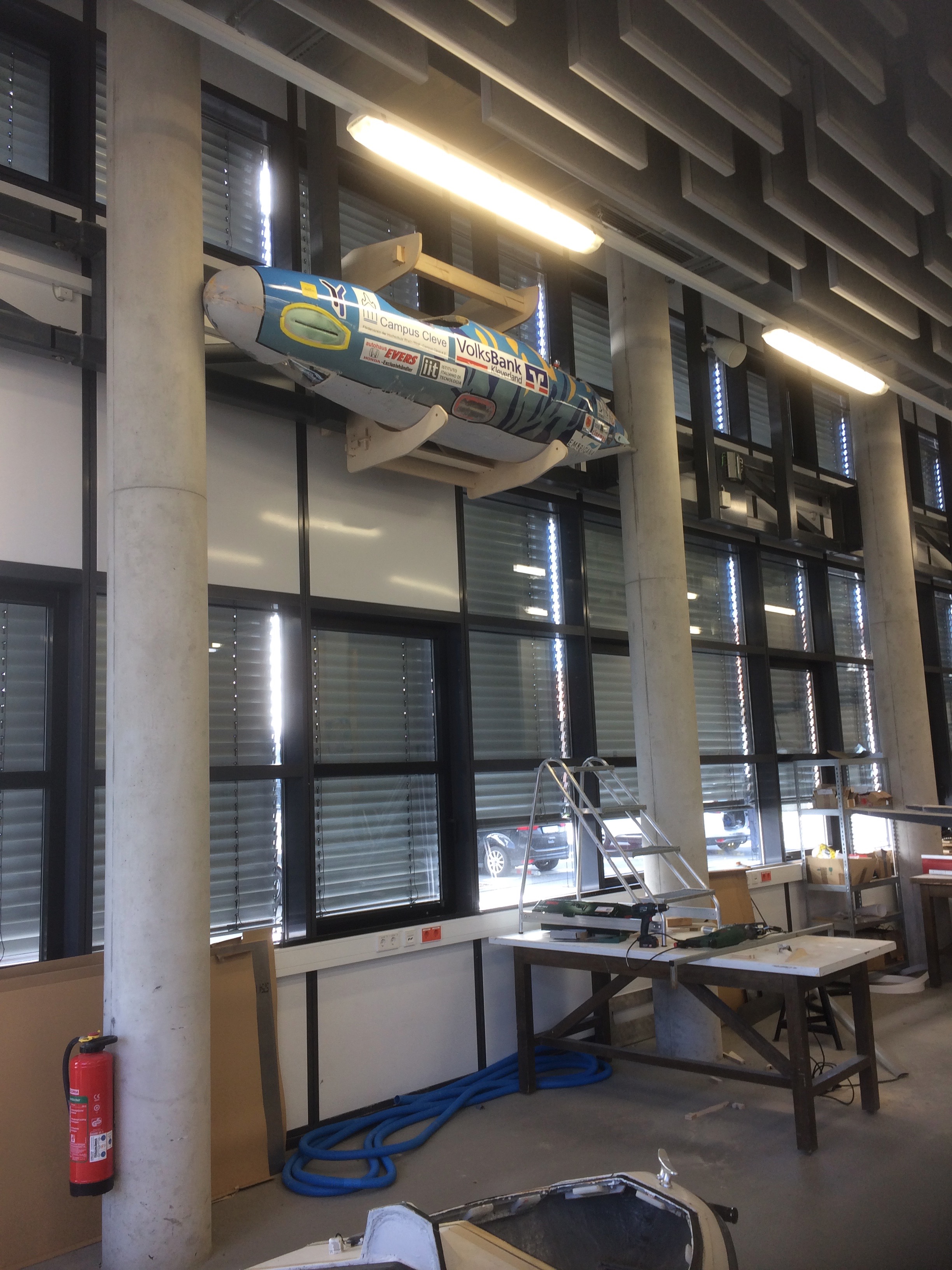
Installation
Scuba Tank Cart
We have a challenge in the lab, in that the University’s safety people are struggling with how to fit our diving activities into the strict rules about the storage of gas cylinders. The problem boils down to whether a cylinder is “in active use”, and therefore permitted to be in a lab, or “in storage”, in which case it must be committed to a dedicated storage facility. The rule is designed to handle large cylinders that might be found in a chemistry lab, but it doesn’t work well for scuba tanks (which after all aren’t regularly found in the German university environment, at least not in North-Rhein-Westphalia.)
The compromise we’ve worked out with the authorities is to formally demonstrate that the cylinders are formally “in use” (which is the truth - we just have to make it obvious). So what this means is that the cylinders have to be arranged in a cart on wheels which prevents them from falling over.
The Design
I’ve opted for the castellated plywood approach in my design. Keeping with the FabAcademy tradition, I’ll avoid nails, screws and glue (for now - the weight of the tanks and the rough handling my require some fasteners later. We’ll see.)
I’ve stuck with SolidWorks since that’s what I know. I’ve dug further into the help files and discovered a way to do parametric design directly in the program. It’s a bit fiddly, but it works ok, at least for the initial laying out of the elements.
The trick is in the use of the Equations tool, combined with the linear sketch pattern tool. It’s not quite the easy parametric design approach of OpenSCAD, but it works.
I started by drawing a dive cylinder. We have two sizes that need to be transported in this cart, one of 3L capacity and one of 5L. The tank consists of a cylindrical body, squashed hemispherical base and a shoulder/neck at the top.
I drew the 5L tank first, with all sizes referenced to the diameter of the cylinder. I then saved a copy, which I made into the 3L tank simply by changing the diameter of the cylinder. In retrospect, it would have been even easier to do by drawing the radial section in one plane, then revolving the whole thing at once.
Once I had all of the cylinders available, I started on the top of the cart. The first step was to set out the overall dimensions of the cart, which were done parametrically based on the diameters of the cylinders and a set width of plywood between the edges of the cylinder holes and the sides of the top. To set the parametric size, I first created a rectangle in the usual way and accepts it, then used the Smart Dimension tool to update the size of the rectangle. Because I was going to round off the corners, I added two construction lines between the centres of the rectangle’s opposite sides. Then I used the Smart Dimension tool to set the lengths of the construction lines (and thereby the overall shape.) As shown in the figure, this can be done parametrically by writing in an equation into the Smart Dimension pop-up box. Quotes are used to create new parameter names.
The parameters are all to be found in the Tools:Equation command.
The Equation system was messy until I figured out not to export the equations, only the global variables.
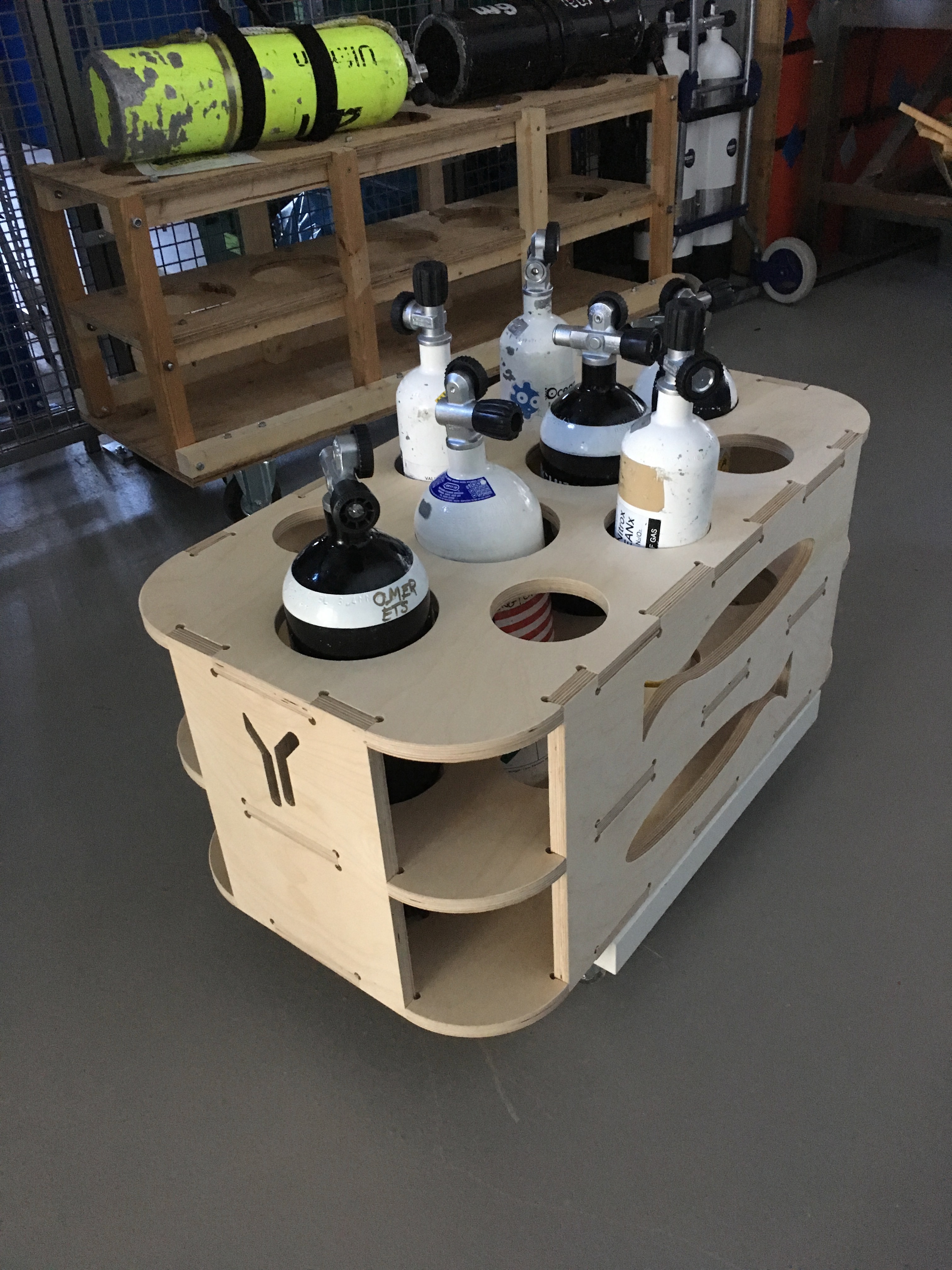
Anyway, long story short, here’s what the beast will look like.
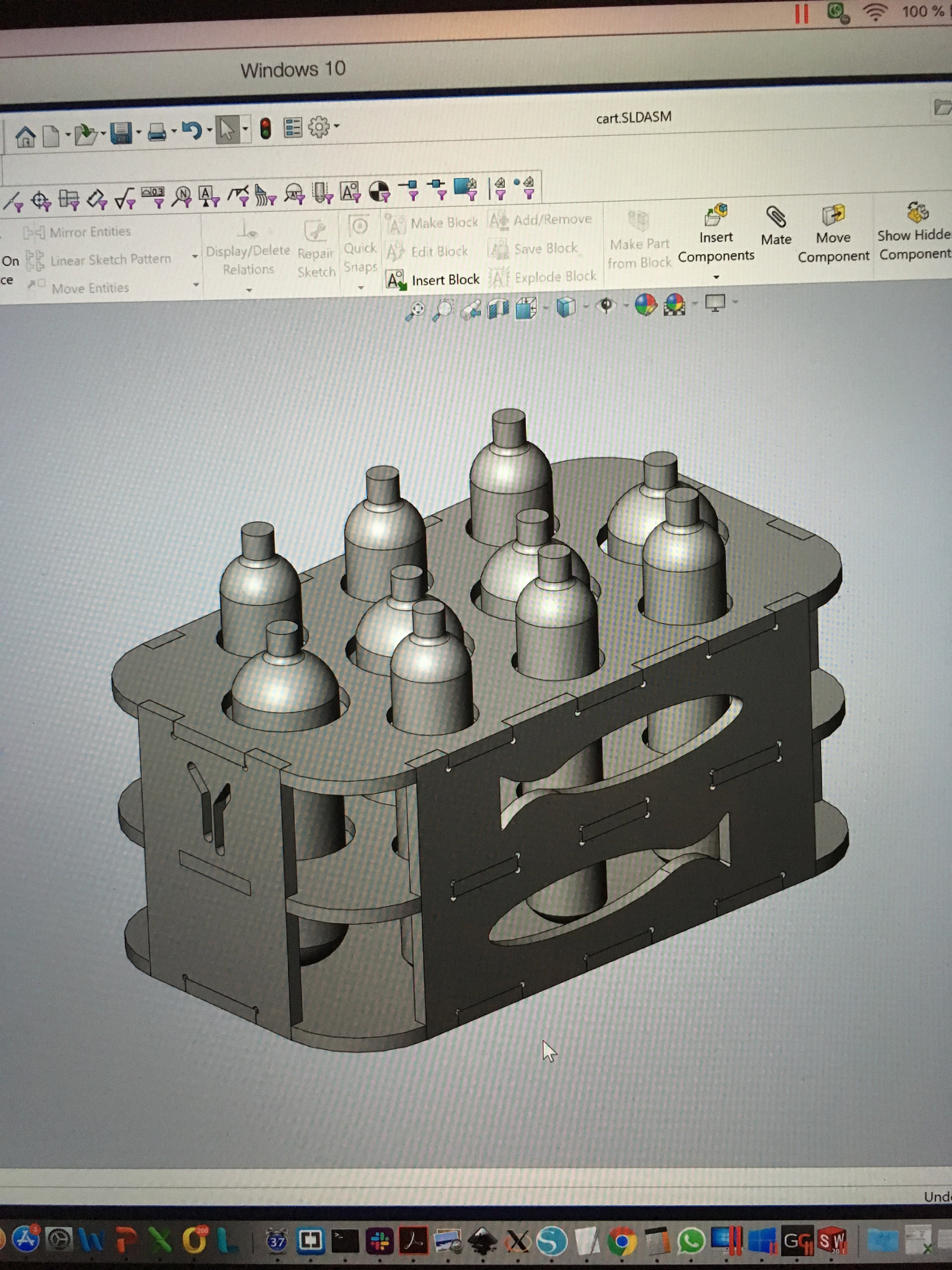
The CNC machine getting started:
And this is the cart in nearly completed state. The only thing missing is the casters. In the background is the first cart we made in the lab using the available hand tools. The CNC machine does a much nicer job!