4. Computer controlled cutting
Here we go - bringing CAD creativity out of the matrix into the real world.
Vinyl cutting
The vinyl cutter is a fun tool which introduces the user to the next step beyond the laser printer. The machine looks and feels like an inkjet printer, but goes further and cuts out shapes from thin and relatively soft materials.
Cutting vinyl - making a sticker
The first step was to select a graphic to make a sticker out of. I opted for a logo I’d made in powerpoint for a fictional submarine racing team.

The multicoloured image was obviously not appropriate for vinylcutting, so I edited the image to create a black and white version.

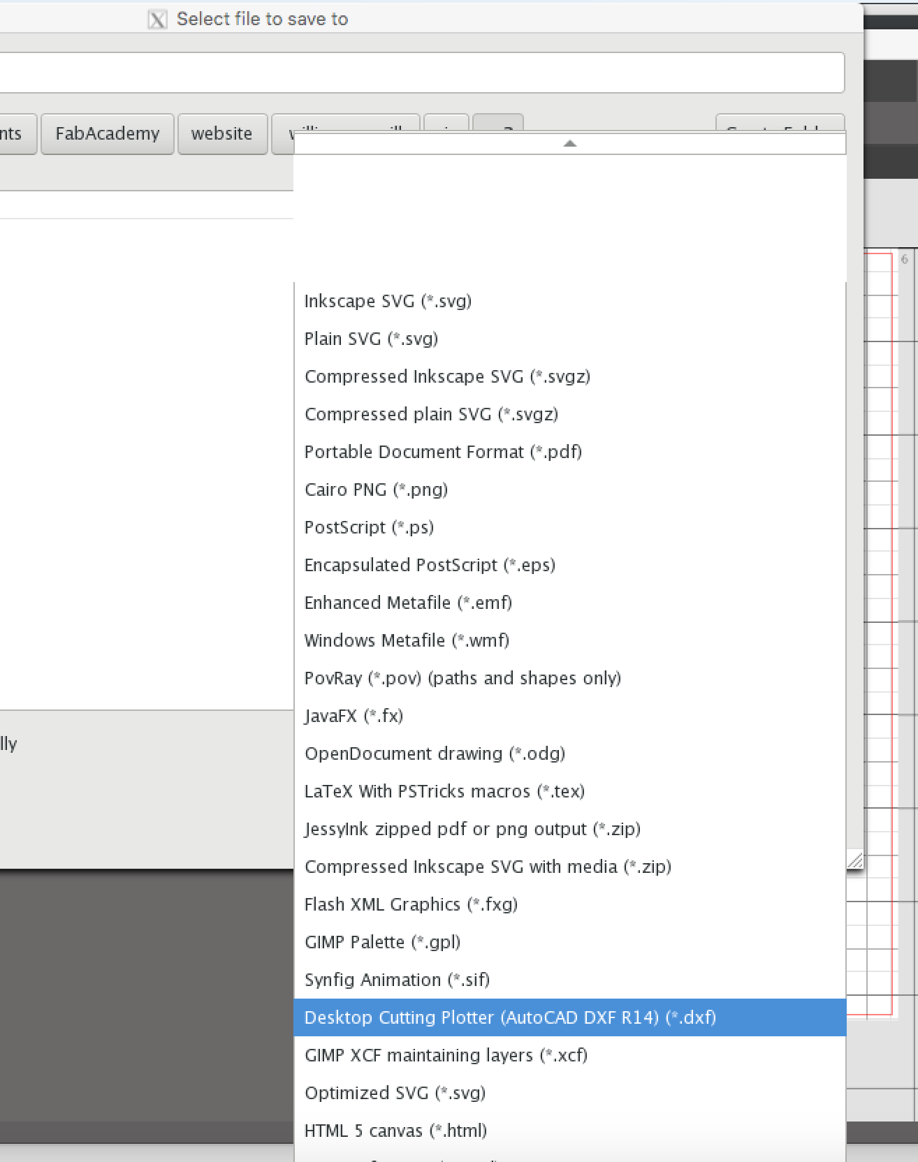
Then it had to be vectorised. The new png file was imported into Inkscape. Since it was already a monochrome image, it could be simply saved as a DXF file using the setting below, ready for the cutter software.
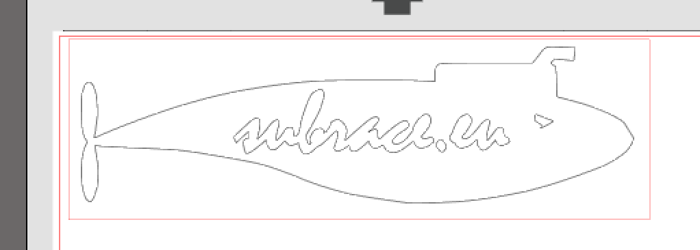
The file was opened with the vinyl cutter’s own “Silhouette” software, which loaded it as an outline. This was then scaled and surrounded with a rectangular box, as shown.
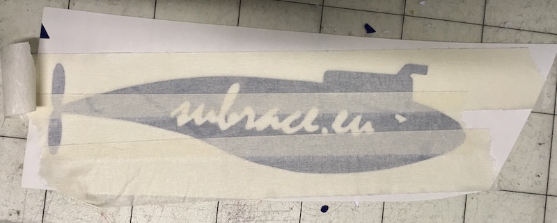
This was ready to be sent to the machine. A blue coloured vinyl sticker sheet was sourced and stuck to the template provided with the machine, taped in place along the edges with masking tape. The template and vinyl were then fed into the cutter. The cutter blade was tested on a small piece, and we found that it had to be set on depth “3” in order to cut completely through the sheet.
The printer was then turned loose with the file and it generated the desired pattern. On completion of the cutting, the vinyl and template were removed from the machine, and sticker was peeled off the template. First the negative was peeled back, carefully using a scalpel to hold down the delicate parts, and then the same scalpel was used to separate the centres of letters and some of the contained parts of the logo.
The cutout was then stuck onto the lid of one of the lab’s Macs, next to the text-heavy sticker I made last year.

Laser cutting
After the first exercise in computer controlled cutting on the little vinyl cutter, it was time to get started with the fire-making machines.
The “big” lasercutter we have in the lab is a 60W Epilog Fusion machine. Here’s an artistic shot from last year showing the front panel.
![]()
The standard operating procedure for this machine is as follows:
Preparing the print job
As far as the controlling computer is concerned, the laser cutter behaves just like a printer. The trick is to prepare the job with the correct attributes so that the printer driver knows how to interpret the image.
The first step is to distinguish between raster and vector graphics. Scans covering a surface area are typically done with raster graphics, while lines are generally done with vectors. The printer driver can handle both, even in the same job, as long as the settings are appropriately entered.
Group work
I took part in the team exercise last year, and I’ll provide a link to our team page as soon as I find the documentation.
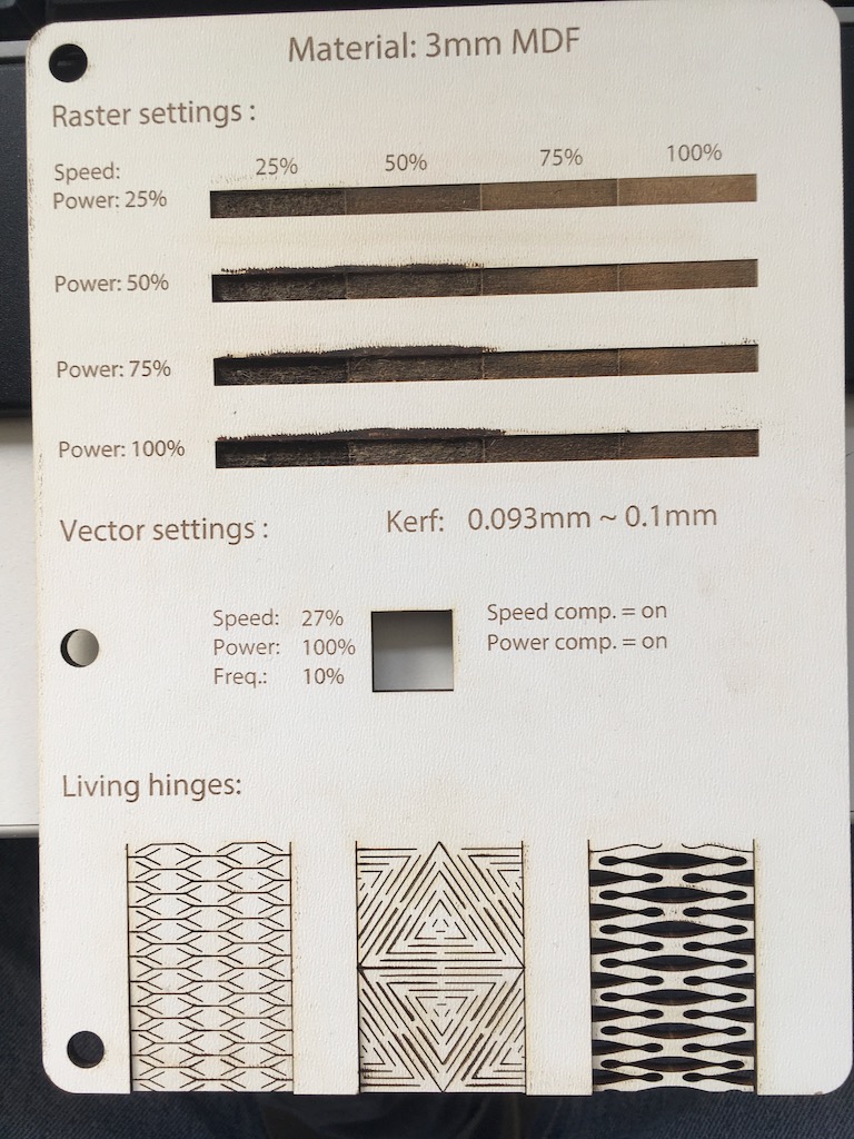
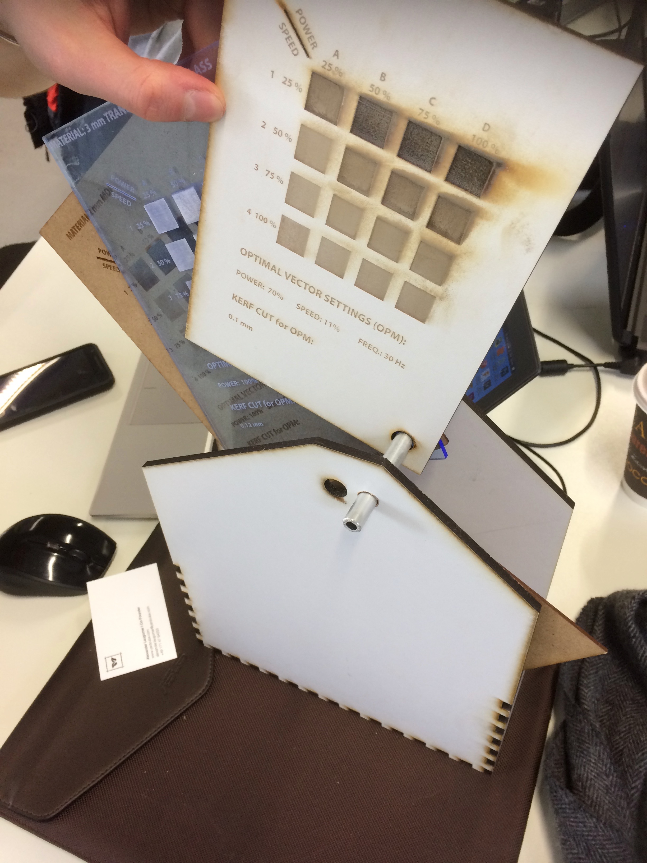
The team this year did a fabulous job of exploring the laser cutter’s capabilities, and summarised it on a bit of MDF.
Simple etching & cutting
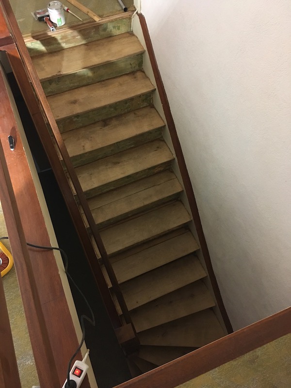
My individual laser cutter project this year was to make some risers for the stairs in the house my wife and I are renovating. The stairs were covered in a layer of horrible carpet which had been glued to the wood, which had been painted in the 1950s fashion with a thick coat of red floor paint. The carpet came off ok, but the glue residue and paint removal was a backbreaking and soul-destroying job which involved a lot of sandpaper disks and a rotating wire brush tool for my power drill. Here’s the state of the staircase after the dust had settled.
Without the assistance of gravity, the risers would have been a nightmare to sand back to the wood, so I gave up and decided to cover them over with white vinyl-coated MDF. This is where the laser cutter came in.
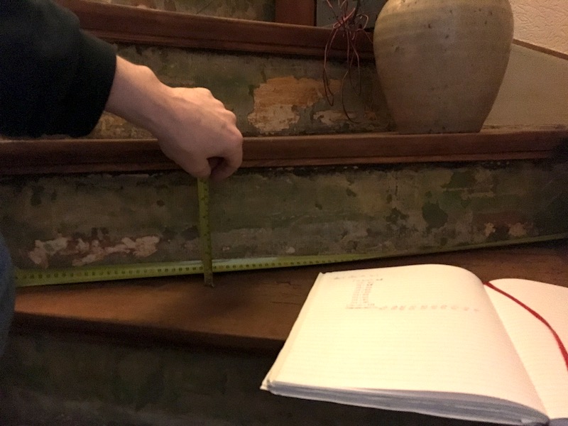
The staircase wasn’t particularly high quality when it was made back in the 1950s, and none of the steps are exactly the same dimensions. I therefore had to measure every step and take into account some of the less-than-straight edges.
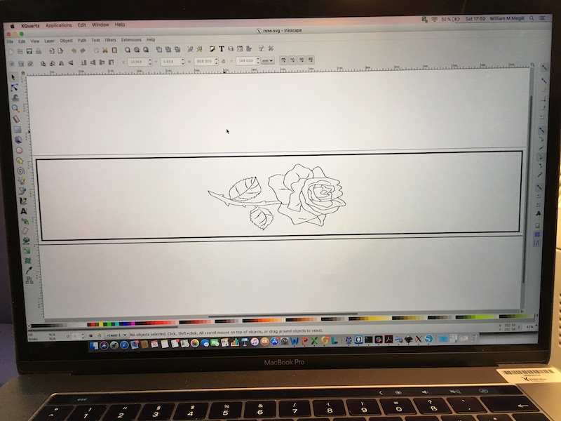
I drew the risers in Inkscape. For the non-rectangular risers, I used the edit nodes tool. To spice up the staircase a bit, I decided to add some artwork to some of the risers. I downloaded a line-art rose from the net, and imported it into Inkscape. Here’s a typical screenshot from Inkscape.
Then it was off to the scanner station. The Inkscape drawing was saved as a DXF file, and this was imported into Rhino, where the two operations (cut and engrave) could be assigned to the graphics. The trick was to define the thickness of the box line to 0,001mm, which indicates to the lasercutter that that line is to be cut right through. The engraved lines were given a thickness of 1mm.
The file was then printed from Rhino. Using the settings described by the team on their MDF info-board, I set the print dialog as follows.
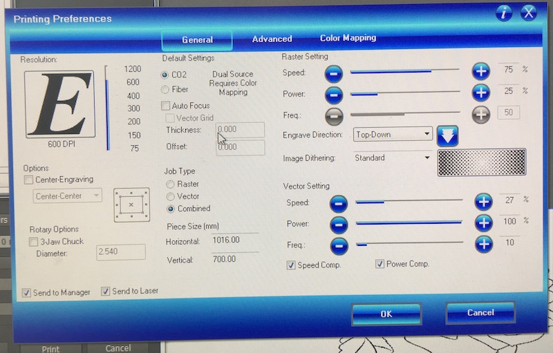
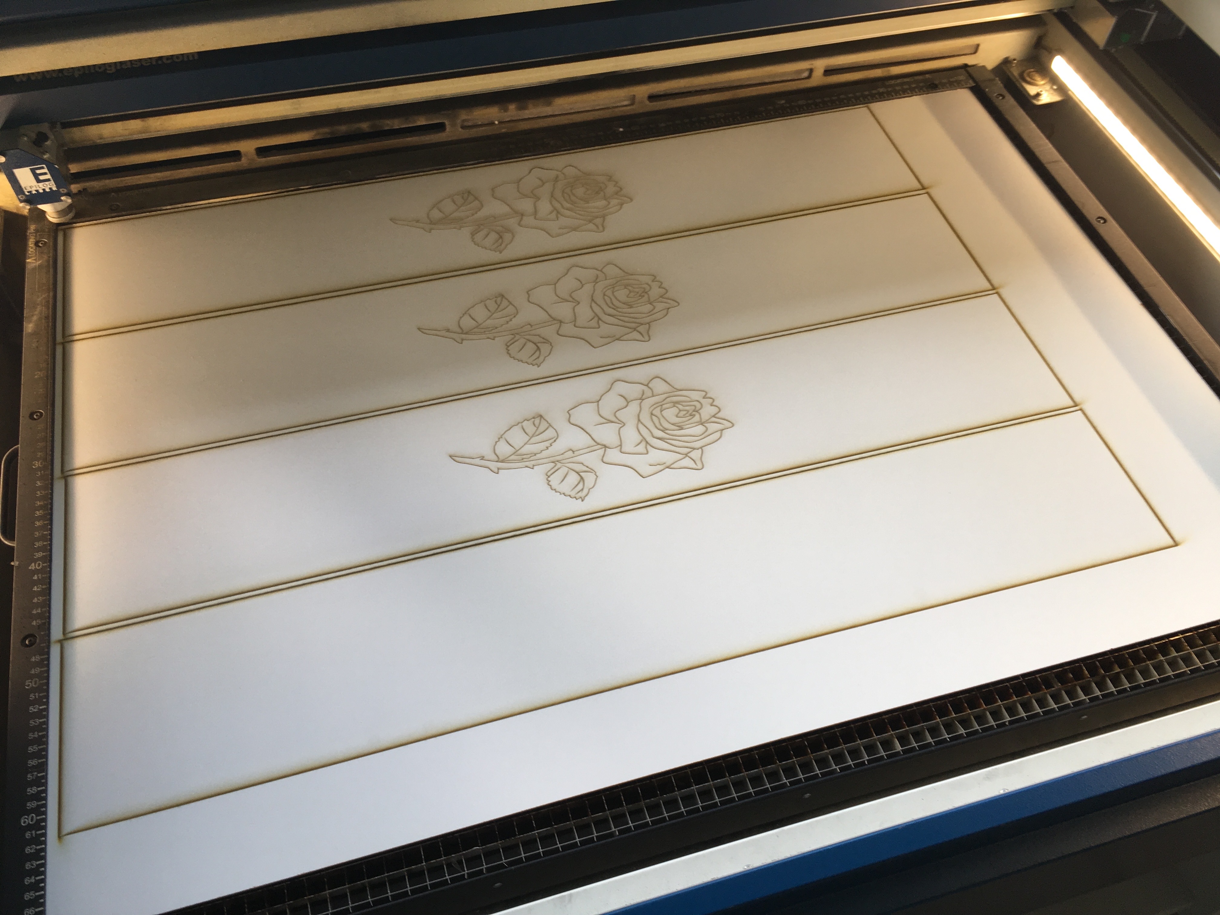
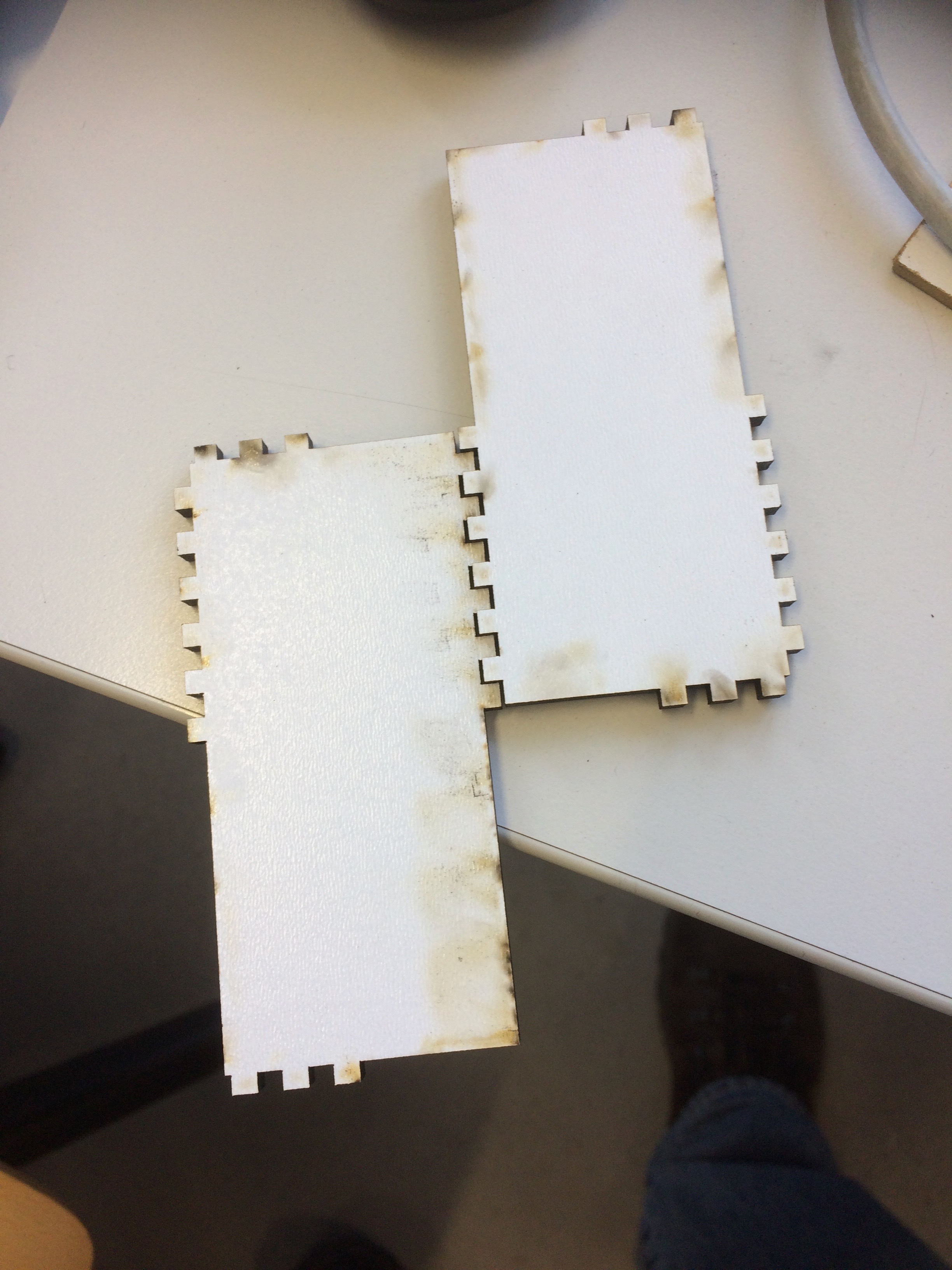
For some reason, the lasercutter didn’t enjoy the “combined” job type, so for the rose-containing pieces, I did the job twice, first to engrave the rose using the raster settings, then second to cut out the riser using the vector settings. Partway through the job, here’s what they looked like coming off the lasercutter.
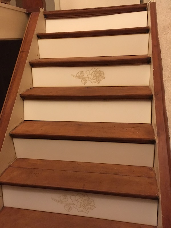
Due to measurement imperfections, the cutouts weren’t perfect fits to the spaces on the stair risers, so they didn’t just pop in. I’ll have to cut them down by hand a bit, but here’s a temporary image to show more or less how it will look when it’s done.
Parametric design
The objective of this part of this week’s assignment is to design something to be cut out on the laser cutter whose size can be adjusted parametrically. Rather than having to go back into the CAD and adjust every point, the concept is to adjust a single parameter that then stretches or shrinks everything appropriately.
OpenSCAD
The obvious easiest CAD package to do this work is OpenSCAD, which does its drawing using a conventional programming language. There are some idiosyncracies to the language, but as I described in the first exercise, once you get used to it, the power of the program is obvious.
To make a fully parametric design, I started by defining a program structure. Overall parameters would be followed by a section including information about the various parts. Then would come a set of “if” statements to control the display of the parts. Next modules were created to control the creation of the parts themselves. Finally a pair of modules created the castellation in x and y.
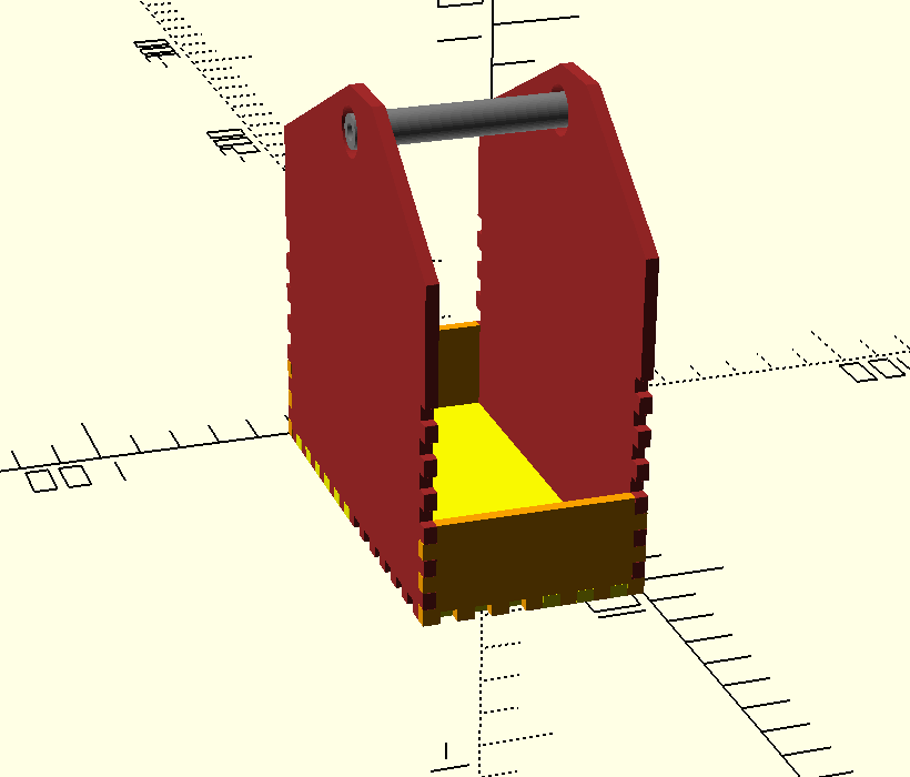
I’ll describe the program in the next updates. Meantime here is what it produced. The code that produced it is down at the bottom of the page.
To cut the parts on the laser cutter, I commented out the “linear extrude” commands from each of the part descriptor modules, then selected one part at a time, with a rotation of [0,0,0] so that it sat flat on the x-y plane, rendered the object, and saved it as a 2D DXF file.
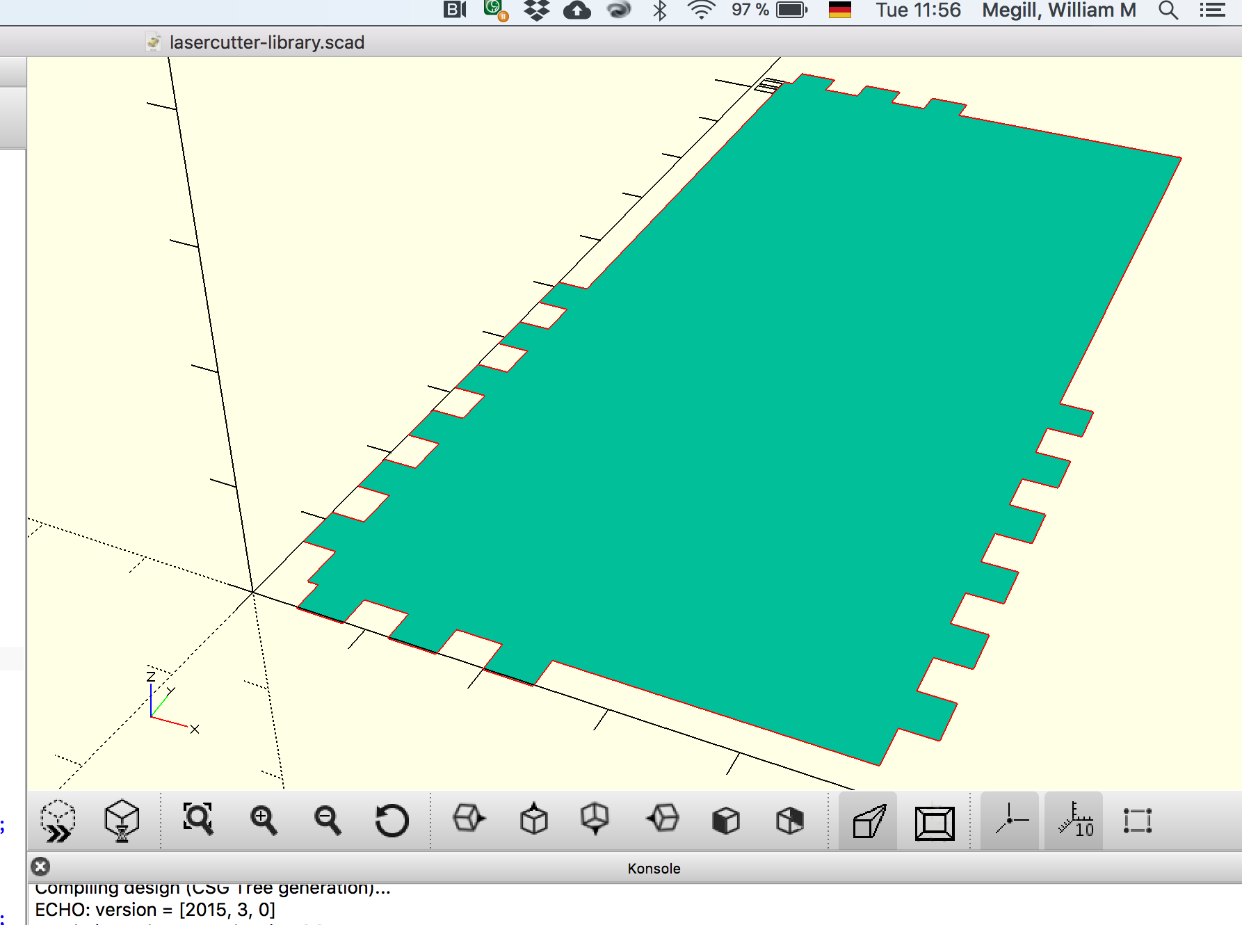 A 2D rendered model of the base.
The DXF files imported quickly and easily into Rhino. From there I was able to print directly to the lasercutter using the settings the team had determined earlier in the preparation of our “book” pages.
 The first cut outs of the base plate, made in 5mm MDF.
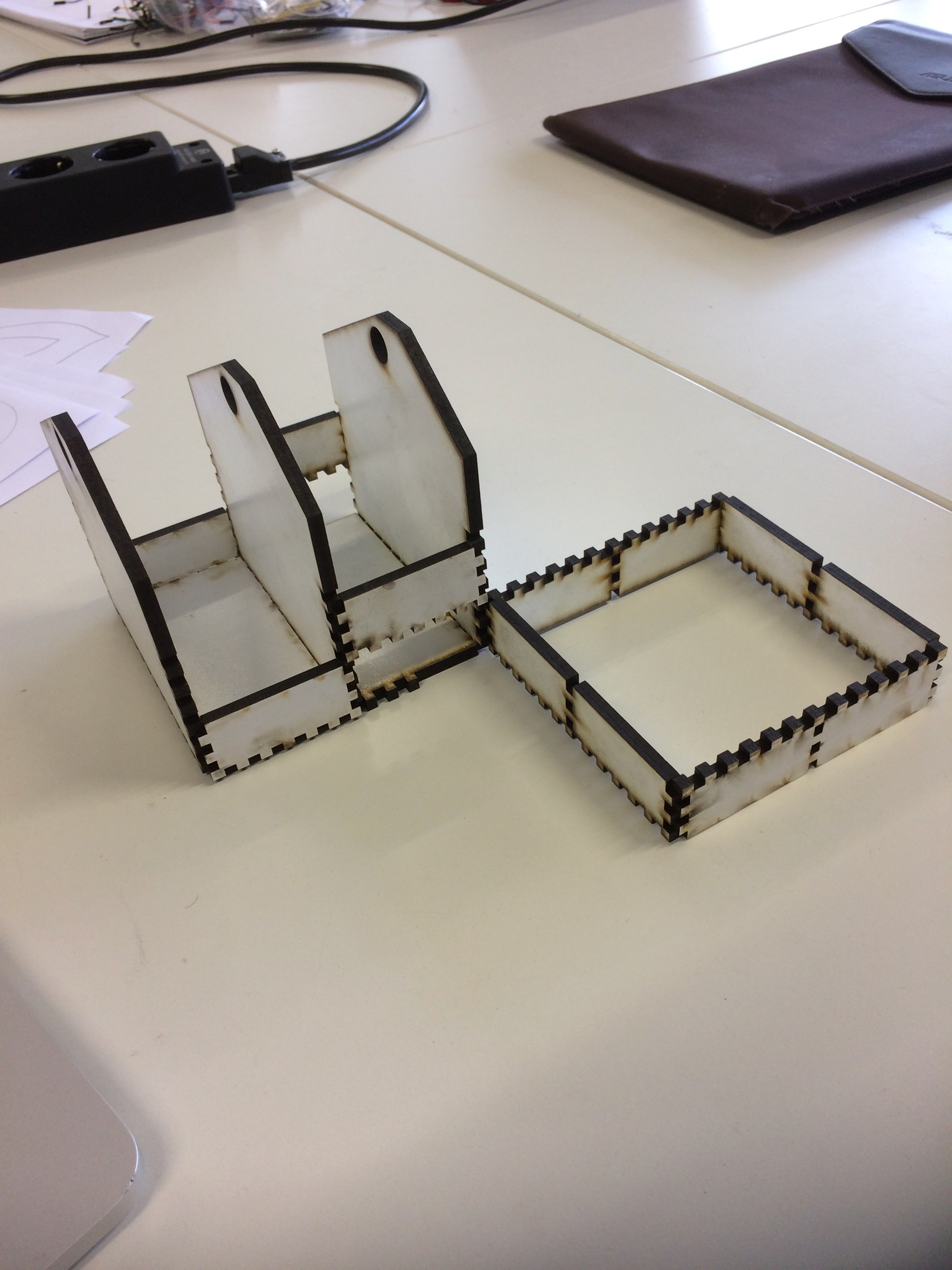
I repeated the process for the rest of the parts. It was only as I started to assemble it all that I realised that I’d goofed. In my program, I had set the code for 3mm MDF, but in selecting a bit of it from the materials cart, my mind was already in full-size gear, so I pulled out a 5mm piece. The cuts were ok for depth, but the extended bits I’d made to connect multiple units together didn’t fit, as the holes in their middles were narrower than the thickness of the middle vertical wall. So instead, I made a virtue of necessity, and made them into a fenced off bit of “garden” next to my “house”:
 A scale model of the final project, made to test the process.
 The final project, now at full scale. All that was required was a quick change to the sizing parameters.
Downloads
- [OpenSCAD code](../images/week04/library.scad.txt) DXF Files
- [Base](../images/week04/library-base.dxf.txt)
- [End Wall](../images/week04/library-end-wall.dxf.txt)
- [Back](../images/week04/library-back.dxf.txt)
- [Front](../images/week04/library-front.dxf.txt)
- [Long back piece (section joiner)](../images/week04/library-long.dxf.txt)
Again, in SolidWorks
In my second year, I redid the parametric design, but instead of doing it in this week’s assignment, I did it with the “Make Something Big” assignment. More details here.