7. Electronics design
Week 07: Another week, another board to fabricate…today, I will produce the “Hello Ehco” board. I actually find the process of making a PCB rather enjoyable and look forward to the work session.
The Group Assignment page is here
Drawing the PCB with Eagle EDA
Referring to the board diagram provided by the tutorial…
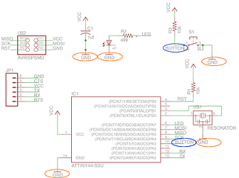
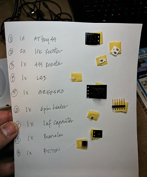
…I compiled a list of the needed diagram components for the “Hello Echo ” board.
- 4x VCC
- 5x GND
- 1x Resistor 499
- 2x Resistor 10k
- 1x Capacitor 1uf
- 1x Resonator
- 1x LED (LEDFAB1206)
- 1x FTDISMD header
- 1x Omron Switch (6MM_switch6MM_switch)
- 1x AVRISPSMD
### …then using the ‘Schematic’ function in Eagle
I replicated the diagram, finding the needed components from the ‘FabLib’ component library
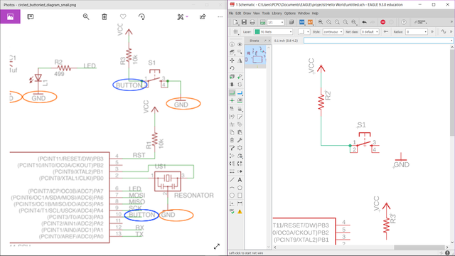
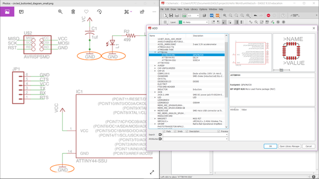
Once the components were laid out according to the reference diagram, I completed it by labeling each critical component by right clicking the component and changing the name.
I ran ‘ERC’ to check for any “Electrical Rules” errors…fixing anything that was identified.
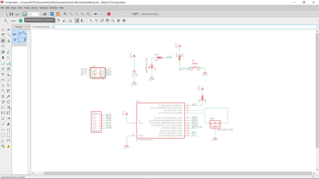
…then I switched to Eagle’s “Board Design” workspace to layout the board.
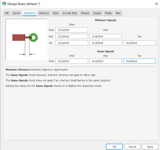
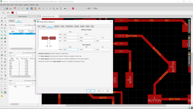
Before preceding with the board layout, I adjusted some Design Rules settings…
Set Grid
- Size: 0.05 inch
- Alt: 0.005 inch (a finer, sub-grid for finer movements…accessible by holding down the Alt key)
Edit Design Rules Clearance
- All settings changed to 15.625 mil (1 mil = 0.001 inch)…which is the diameter size of the sine endmill bit to be used to mill out trace lines (1/64 inch = 15.625 mil)
Design Rules settings done…time to layout the board!
Once again, referring to the tutorial for board component layout work…
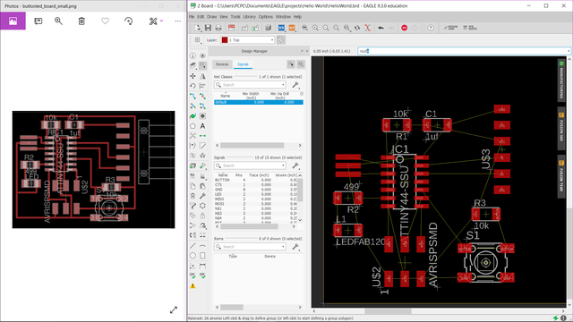
- With the components laid out reasonably close to the reference image, I ran the Ratsnest command to redraw a more efficient set of Airwires (lines connecting tso parts specified as connected in Schematic).
Pro Tip: Keyboard shortcuts can be assigned to commonly used board layout commands using the “Assign” feature under the “Options” menu.
-
That done, I used the Route command to lay trace lines between component pads (to replace the Airwires). I used the ‘Alt’ key often to move components and lay routes on a finer grid.
-
With the layout done, I checked for issues with the DRC (Design Rule Check) command and fixed each error that was identified. For me, the biggest problem were the trace with that ran under the chip…that need to have their widths narrowed to allow for enough clearance through narrow gaps or allow enough space between trace lines.
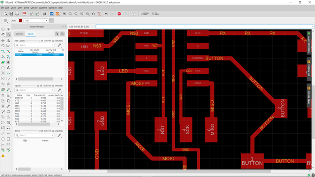
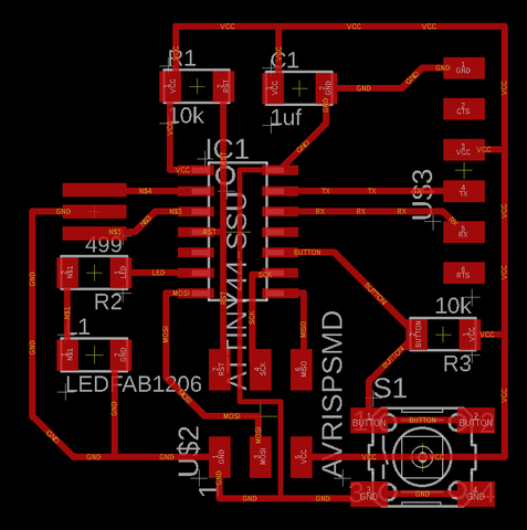
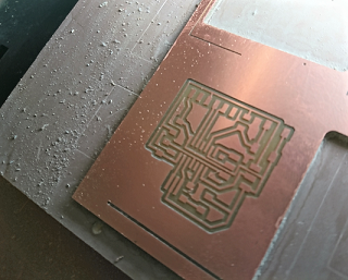
An this is the final board image of my Hello Echo board traces!!
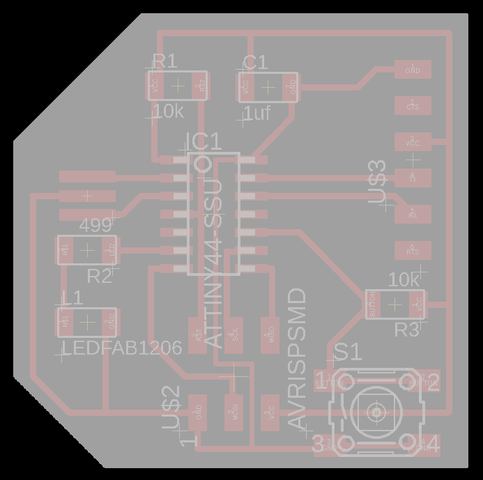
Time to draw the board outline shape!
With the board’s interior trace lines layout completed, I created a board outline shape using the Polygon tool on the Document layer. Click, click, click, click, click…to specify each of the polygon’s vertices and it’s done. Fast and easy.
Last step, shrink the work area defined by the yellow border line
Carefully click and drag each of the boundary edges to bring it closer to the outline of the PCB…leaving a tiny bit of room. I had to work hard to keep the outline shape rectilinear and the corners of the box square.
Exporting PNG files
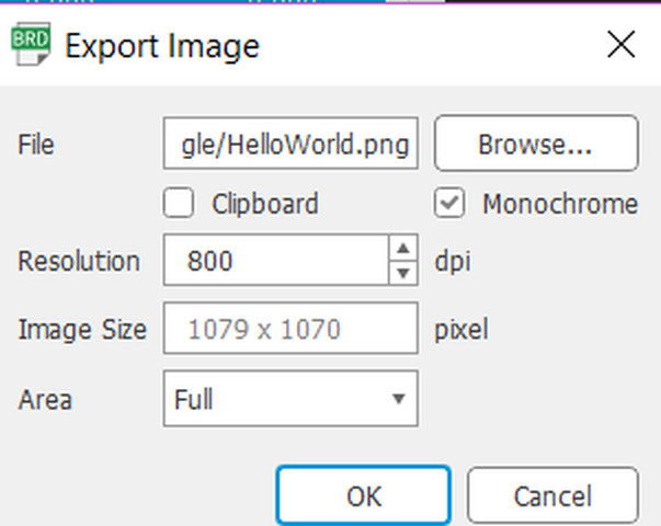
The very last step in Eagle is to export the ‘Trace’ and ‘Outline’ images of my Hello Echo board (which will be converted to RML files for milling by the Roland SRM-20).
- Using the Layer Manager I turned off all layers leaving only the “Top” layer showing the interior trace lines. Under the “File” menu, I chose Export > Image
- Similarly, in Layer Manager I turned off all layers except for the “Documents” layers to show the filled, polygonal shape of my board…and exported the image.
For both the board’s “Trace” and “Outline” image exports, I used the following settings…
- “.PNG” file type
- “Monochrome” box checked
- DPI set to 800dpi
Pro Tip: Also make note of the Image Size in pixels, which will be useful to reconfirm the image size in other software.


Create RML Milling File Using MODs
Setting up MODs for RML file generation:
- Open the Roland SRM20 milling module: Right-click anywhere and choose… Open Server Programs > Roland SRM-20 PNG
- Open “File/Save” module: Right-click anywhere and choose… Open Server Module > File > save. This module will save the RML file into the “Downloads” folder instead of sending it directly to the milling machine via the web socket (our machine is not connected to the network)
- Zero the origin: In the Roland module…change the XYZ origin from 10 to 0.
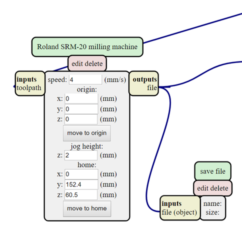
Import PNG file and generate RML file
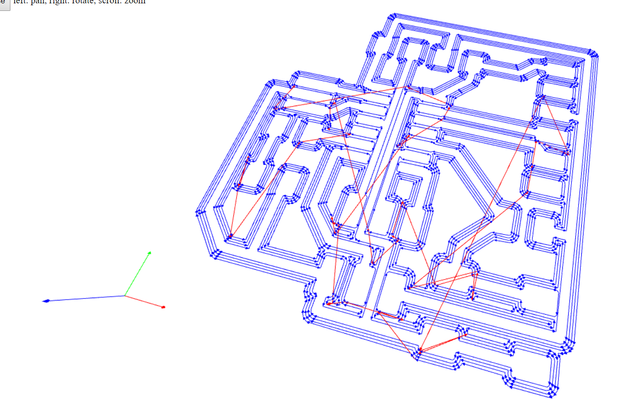
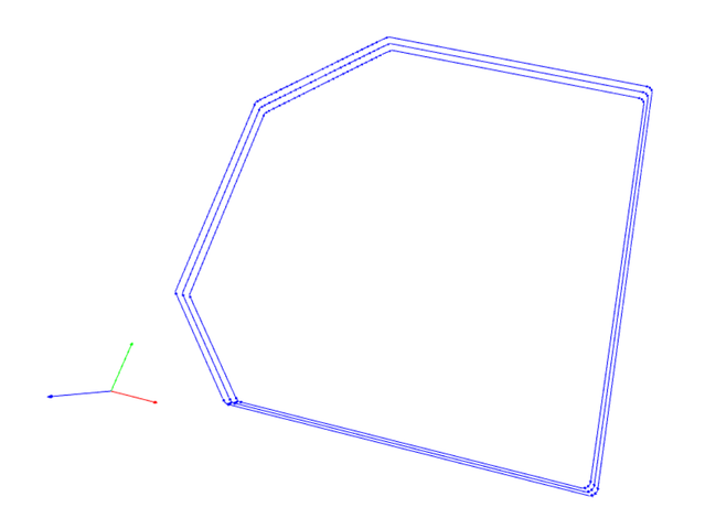
- Select the PNG files one by one and generate the RML files…clicking 1/64 for Traces and 1/32 for the Outline.
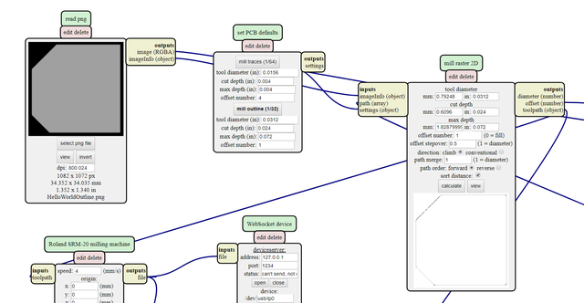
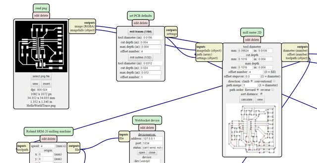
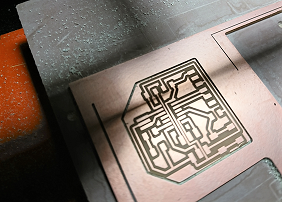
- Check the mill path image for errors....especially pads that are fused together instead of being separated. Make adjustments in Eagle and re-export PNG file to fix issues.
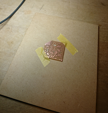
Milling the PCB
- Transfer the RML files using a USB memory stick
- Insert the 1/64th endmill bit into the machine
- Zero the XY origin point then the Z origin point
- Add the trace path file after selecting ‘Cut’ and start the milling process…
- With the traces etched, I swap out the endmill bit for a 1/32 bit WITHOUT changing the XY origin point…set the Z origin point for the endmill biggest
- Select ‘Cut’, delete the Trace file and add the Outline file…start the milling
The 2 RML files are here and here
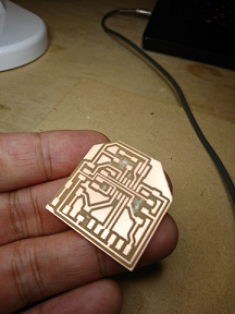
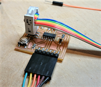
Soldering The Echo Hello World Board
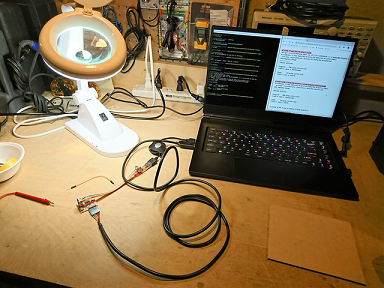
Not much to say here…just knuckle down and get to it. I feel pretty good with my soldering station setup and workflow at this point…
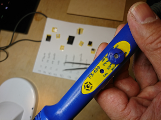
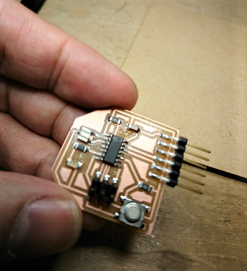
No issues with the soldering. Made certain that the orientation of the chip is correct (dot in upper left position), LED polarity correctly positioned.
Programming The Echo Hello World Board
Programming Preparations
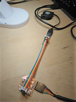
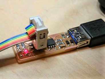
- Connected the FabTiny to the Echo Hello World board
- Important!! Made sure that the pins on the FabTiny programmer are correctly connected to pins on the Hello Echo board. I focused on making sure that the GND pins were correctly connected no the two boards. Doing this wrong could fry the boards when power is applied…I was told.
- Connected the FTDI cable to the Hello Echo board…again, making sure the black GND wire is connected to the board’s GND pin.
- All that done…the 2 lose USB connectors were connected to my PC to power up the boards and prepare for FTDI communication/sending of programming instructions.
Programming the Board
- Downloaded the 2 necessary files for programming Neil provided for the Hello Echo board… hello.ftdi.44.echo.c and hello.ftdi.44.echo.c.make…saving them into a single folder on the Desktop.
- In the Git Bash terminal (not Windows terminal!!), “CD” to the directory where I saved the files and ran the following 3 commands in sequence…according to the tutorial:
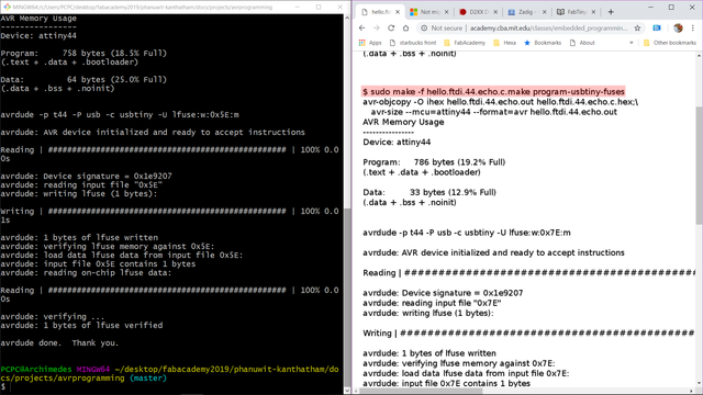
make -f hello.ftdi.44.echo.c.make
make -f hello.ftdi.44.echo.c.make program-usbtiny-fuses
make -f hello.ftdi.44.echo.c.make program-usbtiny
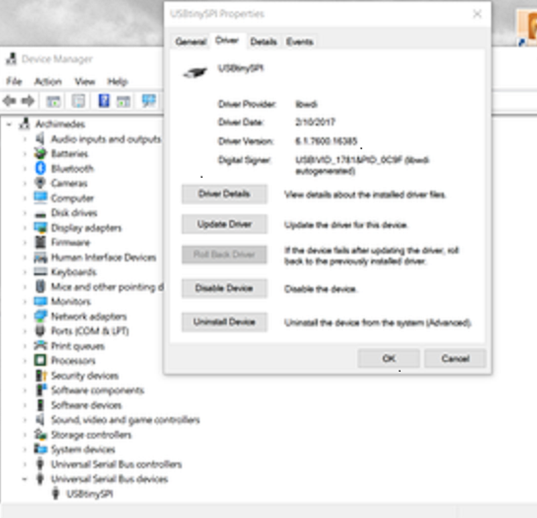
My first attempt…Failed…the error message states “Could not find USBtiny device”
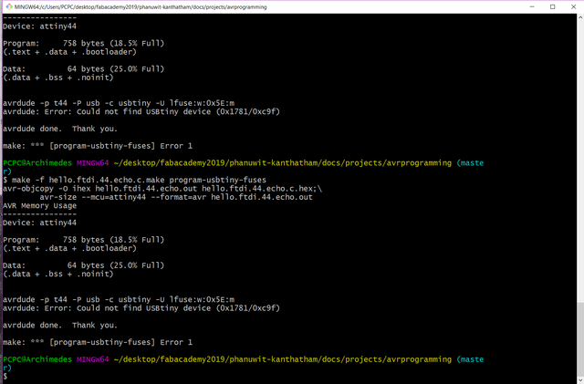
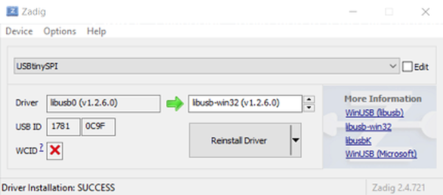
After a lot of diagnosis, the problem appears to be an incorrect driver for the FabTiny…the solution was the installation of the correct, specific driver for the USBtiny using zadig…“lbusb-win32(v1.2.6.0)”
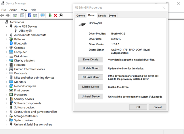
- After installation of the correct driver, I ran the command strings again (Note: I deleted “sudo” from the string…only for Mac OS?)
Success!!!

Testing the Board in Arduino IDE
Unplugging the FabTiny programmer from the Hello Echo board’s ISP pins but leaving the FTDI connected to the board and the PC…
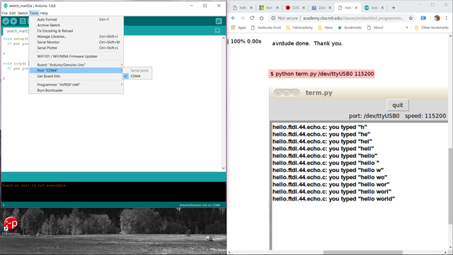
- Launch Arduino IDE
- In the “Tools” menu…
- …select port where the Echo Hello World board is connected…(COM4) in my case
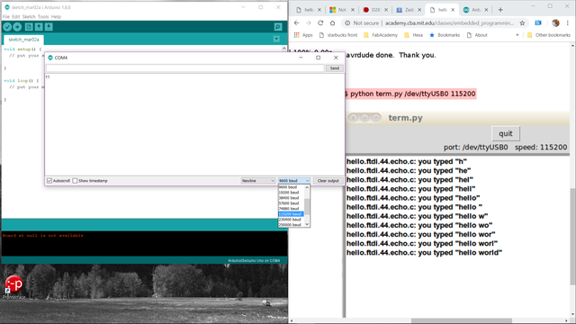
- …open the “Serial Monitor”
- In the Serial Monitor window…change the serial communication Baud Rate to “11520 baud” (lower right corner)
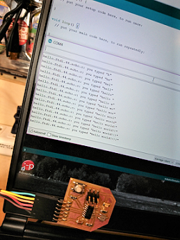
- Test typing one character at a time…successfully received the echo output from the new board!!! Yippee!!!