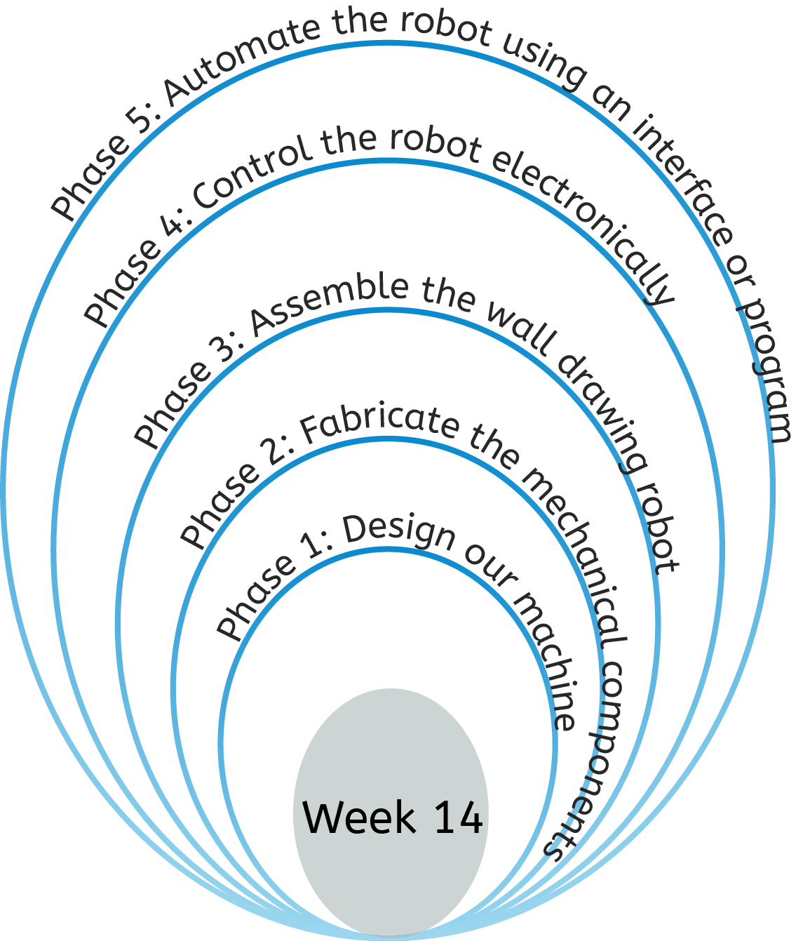
For this week, I am aiming to start my journey in building Fablab 2.0, and documenting every step and design in the journey which will hopefully in 2-3 years help me complete a fablab completely fabricated in a fablab. My first portable and quite easily replicatable machines are a 3D printer and a wall drawing machine, designed alongside my group.
Designing the wall drawing robot
For this week, we are required to collaborate as a group and come up with a mechanical machine design to be realized over the course of the week and programmed to function over the course of the next two weeks. After some discussion and comparison of different machine concepts, we settled on a wall-drawing robot. Since the concept was relatively simple, we aimed to include two colours. The complete group's documentation can be found
The mechanism shown on the right illustrate the complete assembly of the machine. We divided the work between us, taking up the design of the stepper motor side. Ofcourse, we constantly met to share approaches and ideas.
Full assembly CAD
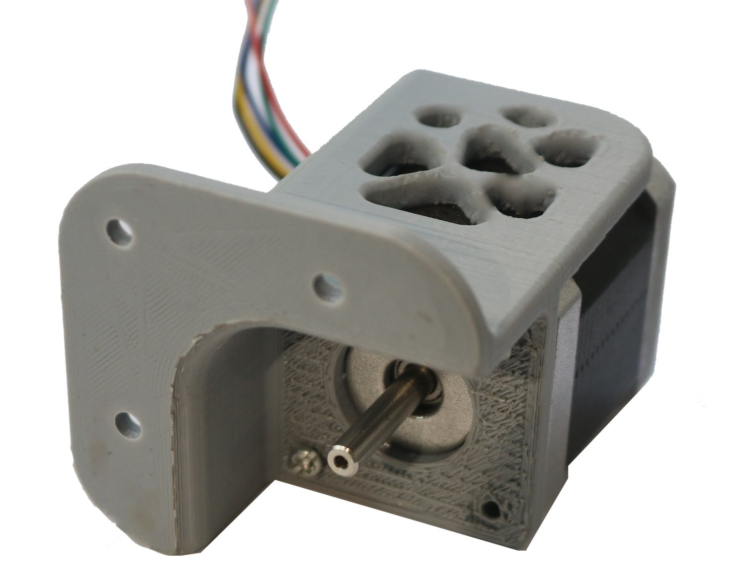
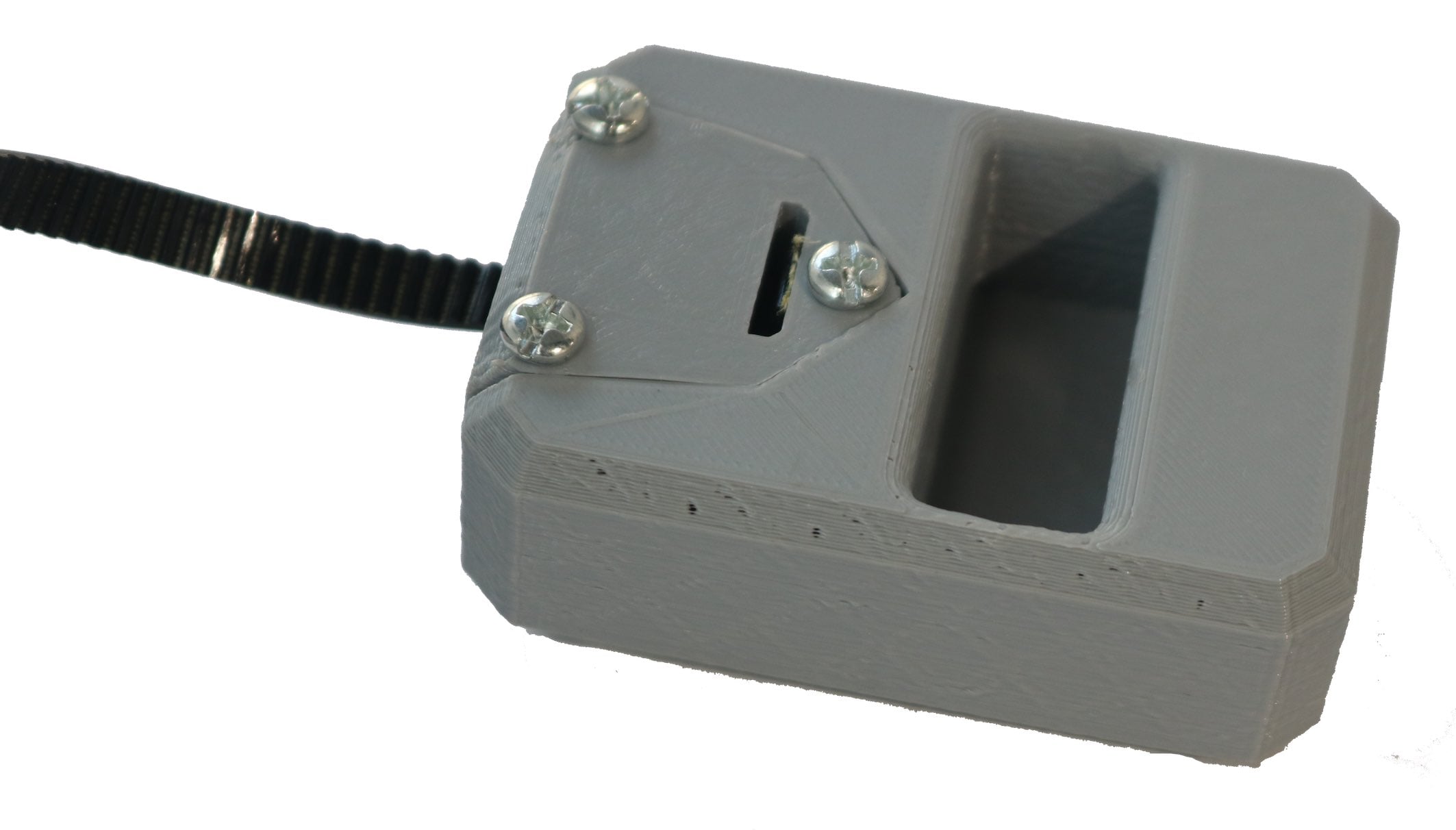
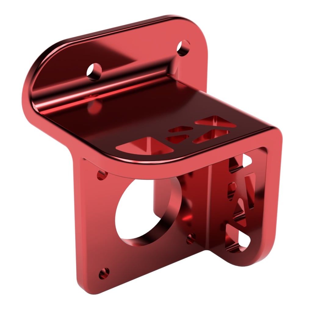
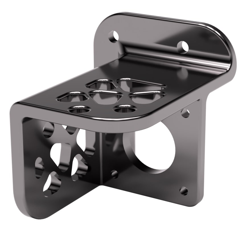
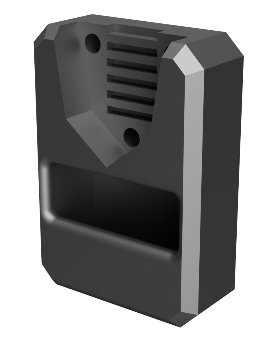
To mount the motors on the wall I measured the dimensions of the NEMA-17 motors available and designed a motor mount with some parametric patterns to decrease the ammount of material used, as well as make it more aesthetic. Initially, it only covered half of the motor height, but we later decided to cover the whole motor to make it look better.
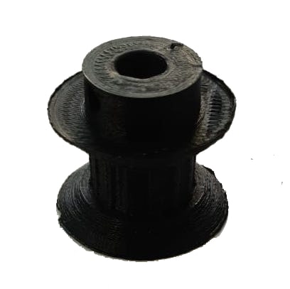
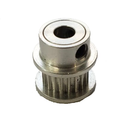
The arm controlled by the stepper motors is a geared belt as it doesn't stretch with force and fits this specific application. We had some pulleys in the store, but when we came to try them on, it turned the socket was way to big for the stepper motor's shaft. I therefore went and designed some pulleys to be 3d printed. Although the pulley worked relatively okay, I decided to salvage some pulleys from old unused 3D printers we had.
The final component of the stepper motor side is the counter weight for the belts. Since our approach was a parallel design approach rather than a waterfall approach, I had to design the counterweight to be modular. Meaning, depending on how heavy the main piece turned out, more weight could be added or removed, by having a pocket into which the weight is inserted. The counterweight piece, also had a complementary piece to lock the belt in place.
I also decided to use a skill I learned along the course of Fabacademy and cast lead weights for the counter weight.
picture of lead weights.
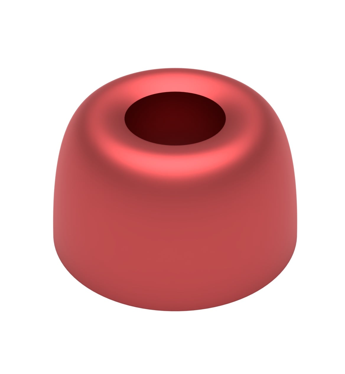
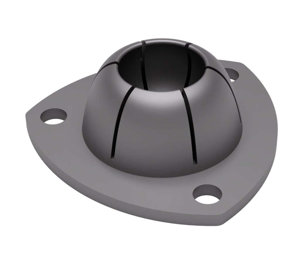
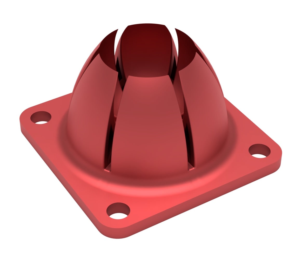
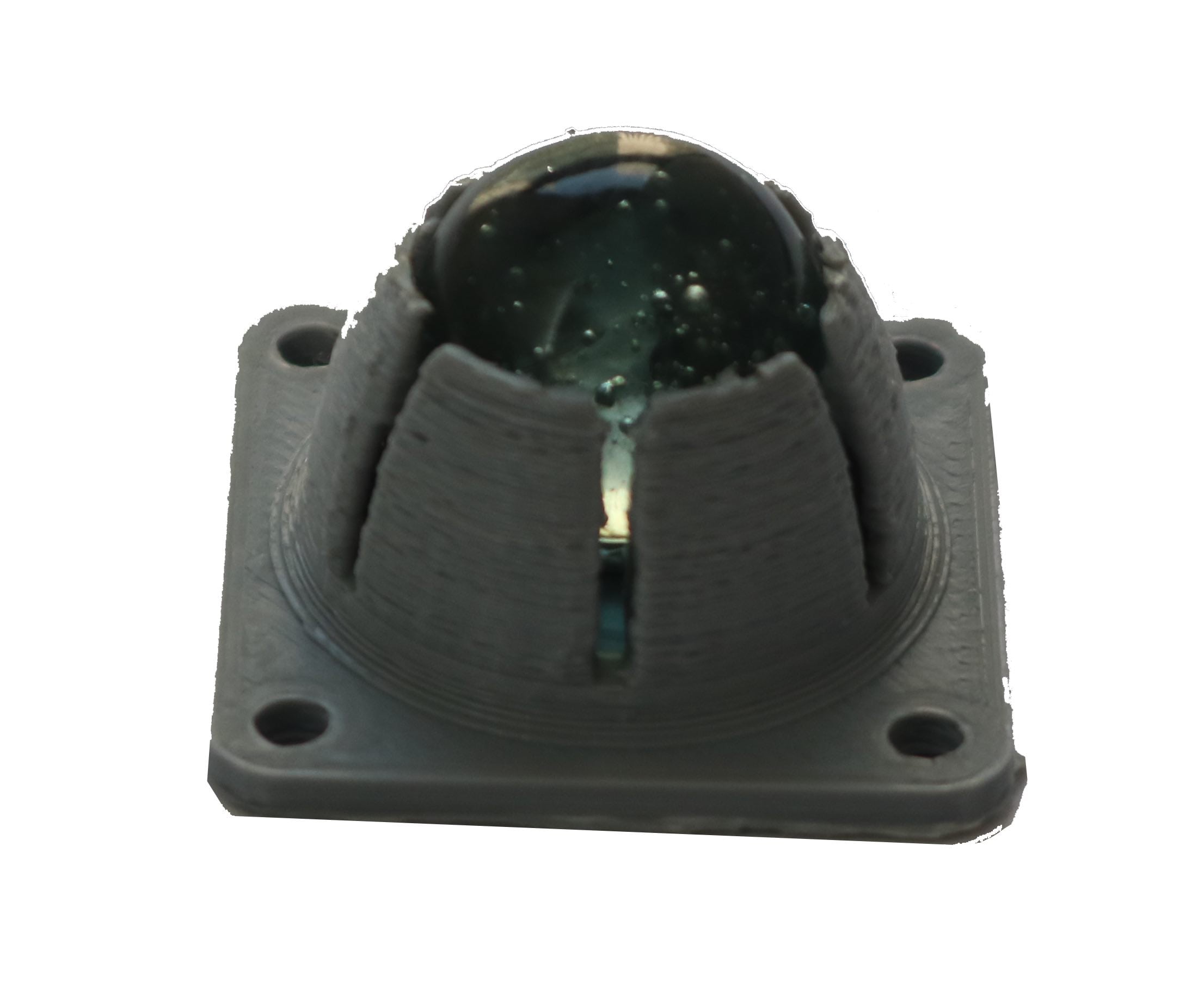
I also worked on developing the marble rollers that will be attached to the bottom of the main piece. They will act like omniwheels and allow sliding of the piece along the wall in any direction with limited friction. This was rather tricky as I tried several approaches, after which I experimented with different tolerances to get tackle fixing of the marble, smooth rolling with only rotation and no translation. The first approach was inserting the marble mid-print, which turned out quite tricky as the nozzle would come in contact witht the marble. The second design was push to snap approach which worked but was too bulky and once the marble was inserted, it couldn't be removed. The third design is the final one we settled on and was a push to snap approach as well, but allowed removal of the marble if required.
Fabricating the wall printer parts
All of the parts I designed, were meant for 3D printing. They were printed using PLA material using out chosen colours, red and grey. I used the Ultimaker 2+ to print the 2.85mm grey filaments as well the Prusa MK2 to print the 1.75mm red material.Below are pictures of the final printed components.
Motor mount
Pulley
Counterweight
Moving the mechanism
In week 16, we had to make automate the machine and control the mechanism to perform a certain action. Since there are quite a few examples of this machine built, the community has developed firmware and programs that will allow me to set up the machine easily… or so I thought.
Since we are using a recycled Ramp 1.4 shield with an Arduino Mega 2650, many of those firmwares and programs will not work from the start. I initially downloaded a program called polargraph and its firmware, only to discover that it heavily relies on the ADAfruit CNC shield library for its code.
I later stumbled across Makelangelo, which in a limited manner supports Ramp 1.4. I installed the firmware and software from this following . Then from the arduino IDE I changed a few lines of code in the firmware, choosing the correct board and pins the motors in the configuration sketch. After uploading the code, I initially checked the serial monitor to see if the board is communicating.
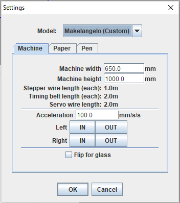
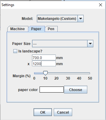
I then setup the machine details by to output the correct gcode, this is done through the setup wizard. This includes the paper size, acceleration and machine size
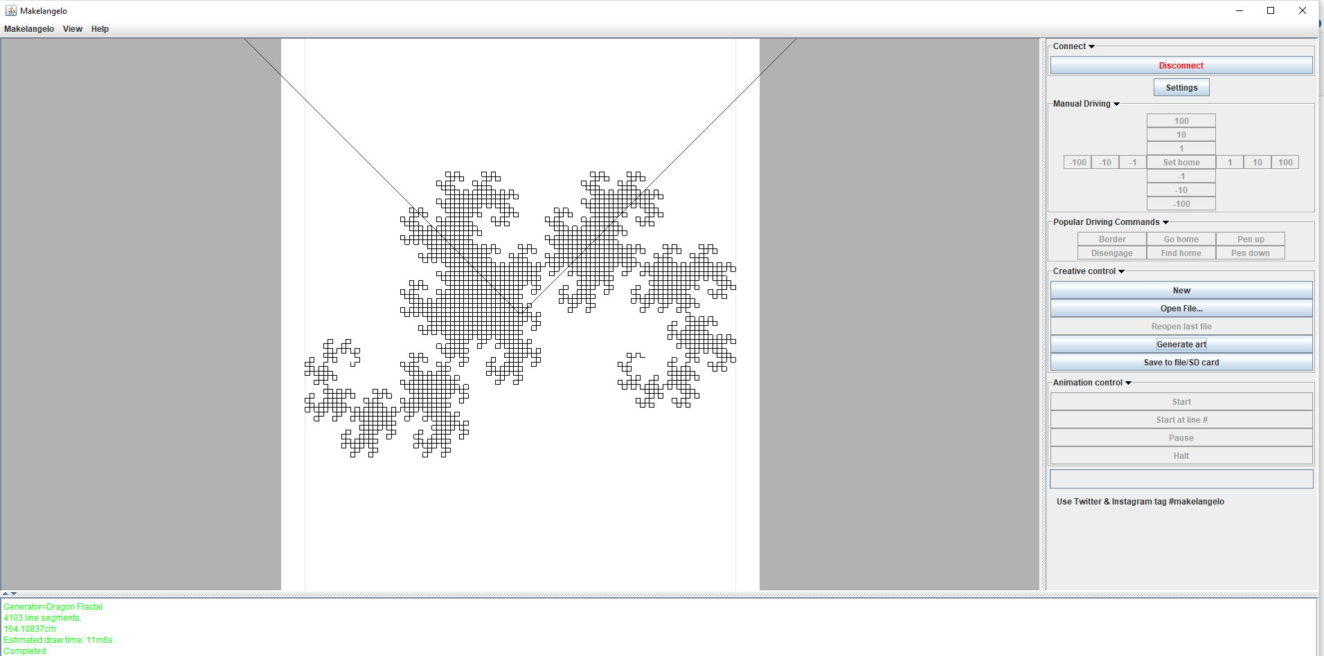
Since the motors were tested individually I hooked them up to the shield and tested out control from the Makelangelo interface. The software, allowed me to manually control the machine, generate G-code but didn't allow me to run it no matter what settings I changed. Whether this was a bug or a way to force you into buying their kit, I resorted to the quickest solution.
I decided to write my own G-code sender for the Makelangelo. The code read the Gcode from a text file and send it through serial to the arduino at a baud rate of 57600, which is the rate at which the Makelangelo is set to communicate. This worked but I then realised that there was a problem with the calibration of the machine.
import serial
import time

t = serial.Serial('/dev/cu.usbmodem14101', '57600')

fname = "/Users/tarekasfour/Documents/Education/FabAcademy/Week16/gcode/drawingc.txt"
delaySec = 1

f = open(fname, "r")

num_lines = sum(1 for line in open(fname))
print ("Number of Gcode lines:")
print(num_lines)

for x in range(1, num_lines):
    now = f.readline()
    print(now)
    t.write(str(now))
    t.write(str("\n"))
    time.sleep(delaySec)
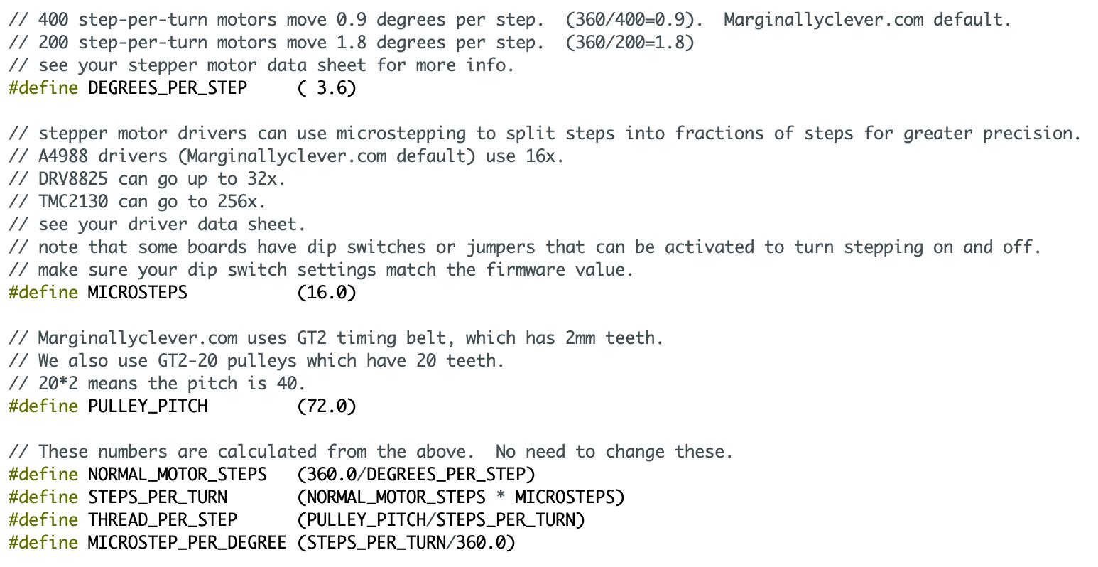
I returned to the firmware and changed a few of the values to match those of my machine. This included the belt pitch, microstepping, clockrate and degrees per step. This allowed me to scale the code correctly to fit the paper.
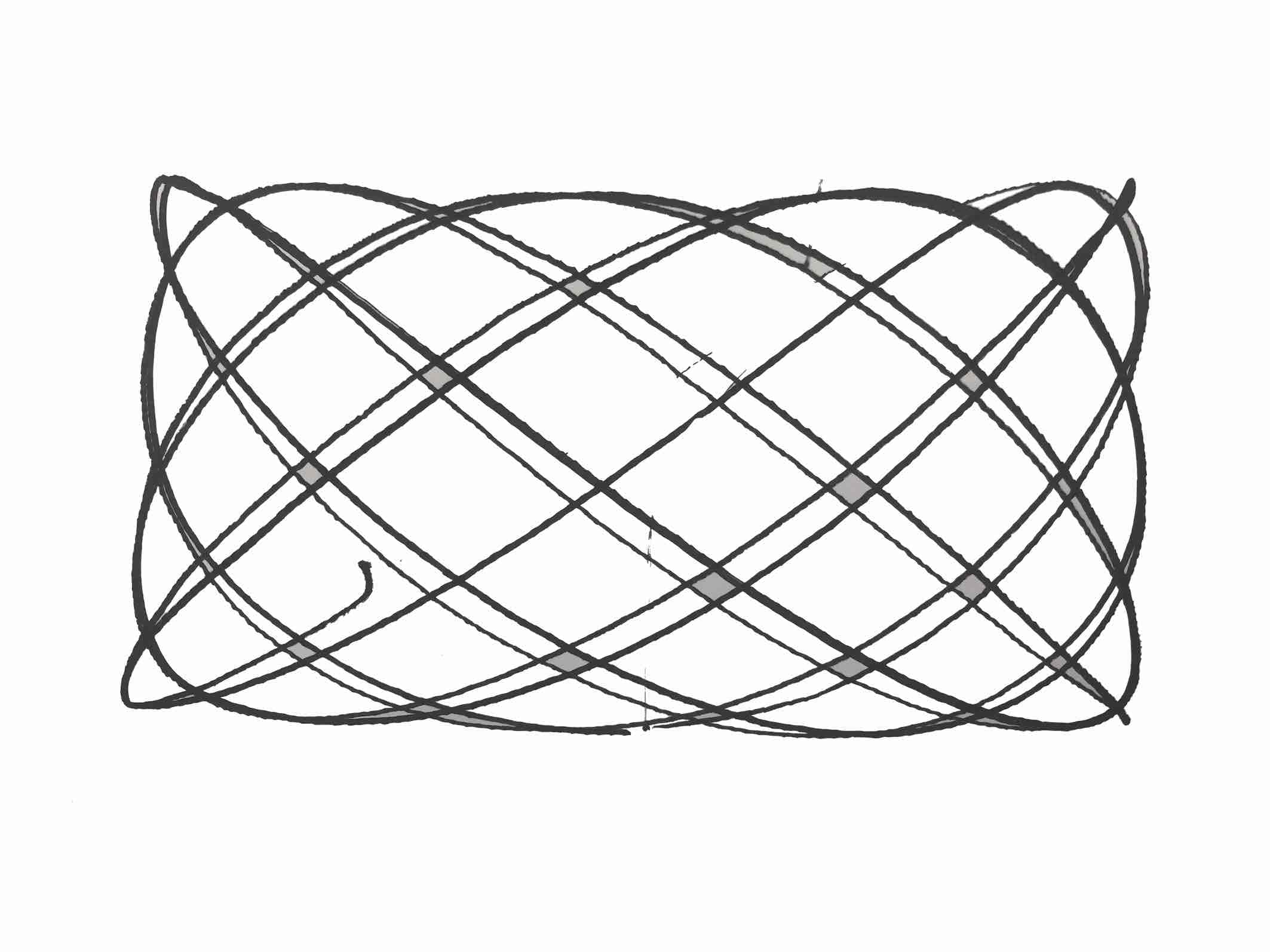
I tried a few times tweaking some settings from the makelangelo software and the firmware until I was happy with the result. Below is a drawing and a video of the machine at work.
Files to download
Please find all the files required, if you feel like making your own:
-min.png)

.jpg)