This week we are required to explore interfaces and applications, programming applications and communicating between different modules to achieve certain features. This week is a chance for me to start the development of my final project system and test out some possible approaches. I'm still fixing my output board and will therefore start testing with an Arduino and afterwards move to my own board.
Controlling an LED
I wanted to start with something simple and control an LED using a python GUI run on my computer.
The next step was creating a new python file,. The file must first include the serial and tkinter libraries. Then
Moving on to constructing the GUI interface, which was explained in a tutorial of python basics by our instructor Nadine. The tutorial went through the basics in terms of I/O setup and syntax of python. The tutorial was done in person and wasn't recorded, but I will explain what was covered.
In order to create start with the first assignment for this week, I needed to install the required files and IDE to code, compile and run python code. I downloaded the pycharm IDE community version which is available for free. After the IDE was downloaded, I navigated to the projecet preferences and installed a few libraries that will allow the programs to run. I installed tkinter, pyserial and arduinoserial to run the GUI, time and serial without any problems. The libraries should show under the project preferences; the following images library management and installation windows, the installation window is accessed from the plus sign in the buttom left of managment window.The libraries are included in the sketch using the following statements
import tkinter as tk
import serial
import time
Then these three statements to setup a window, set the title and the size of the window respectively.
At the end of the program include the following statement
win.mainloop()
to specify that all the statements in between run inside the window.
Frames can be specified in the order that they will be displayed, for example, after defining the window a top and bottom fram can be defined then created
top = tk.Frame()
bottom = tk.Frame()
top.pack()
bottom.pack()
We also covered how to make buttons. The first word specifies the placement, text is what the button displays, and command refers to a predefined function:
Off = tk.Button(top, text="Turn off",command=turn_off)
The predefined function, one to send a serial command for example, is defined as follows
def turn_on () :
    t.write(b'0')
As can be seen the serial is referred to as t, because it was predefined in the beginning of the code, this is done by specifying the port and baud rate used for communication, the serial library is used.
t = serial.Serial('/dev/cu.usbmodem14101', '9600')
For delays using the time library the following statement can be used specifying the number of seconds within the brackets.
time.sleep(0.2)
I wanted to add a few more additions to the interfaces. I used to learn how to include an image in a button. Once the interface was ready, I was ready to integrate the system interactions.
In order to do that , I had to write the following Arduino code that will be running on the Arduino expecting integers 0,1,2,3 or 4 sent by serial from the python script. Each integer sets in motion a different series of statements. This is achieved by assigning the character read into the arduino as an integer using Serial.parseInt(). If statements comparing the integer to preset number, set in motion the predefined functions. For example, 0 and 1 turn on and off the LED respectively. While the the other set the different speeds. At first the program had to turn an LED on and off, as well as blink at three speeds.
#define ledpin 13

int readin = 0;
int readval = 0;

void setup() {
  // put your setup code here, to run once:
  Serial.begin(9600);
  pinMode(ledpin, OUTPUT);
  digitalWrite(ledpin, HIGH);
  delay(200);
  digitalWrite(ledpin, LOW);
  delay(200);
  digitalWrite(ledpin, HIGH);
  delay(200);
  digitalWrite(ledpin, LOW);
}

void loop() {
  // put your main code here, to run repeatedly:
  if (Serial.available() > 0) {
    readin = Serial.parseInt();
    Serial.println("Byte received:");
    Serial.print(readin);
  }

  if (readin == 0)
  {
    digitalWrite(ledpin, HIGH);
  }

  if (readin == 1)
  {
    digitalWrite(ledpin, LOW);
  }

  if (readin == 2)
  {
    digitalWrite(ledpin, HIGH);
    delay(100);
    digitalWrite(ledpin, LOW);
    delay(200);
  }

  if (readin == 3)
  {
    digitalWrite(ledpin, HIGH);
    delay(400);
    digitalWrite(ledpin, LOW);
    delay(400);
  }

  if (readin == 4)
  {
    digitalWrite(ledpin, HIGH);
    delay(1000);
    digitalWrite(ledpin, LOW);
    delay(1000);
  }


}
To link the arduino to the python interface and created basic functions that once linked to a button by adding the command="fucntion_name" to the button properties will run once a button is pressed. The functions were set to send integers from 0 to 4 to the Arduino, each programmed to trigger a different action. However, at first once I uploaded the arduino program and ran the GUI interface, it wasn't working. I decided to open the serial monitor and survey the channel to check if the messages are being sent. I discovered that the integers were being sent in ASCII format, meaning 1 is 49, 2 is 50 and so on. The simplest solution was to replace the serial read on the Arduino program to a SerialparseInt() command, mentioned in the arduino code, which automatically translates the ASCII characters to their complements. As seen below the program worked fine.
This was still quite a simple GUI interface and required some complexity ion both sides. I decided to do that by controlling the blink delay of the LED, using a slider on the GUI. The slider itself was added simply using the Scale option in tkinter, I refered to this tutorial. To send the value of the delay, I decided to simplify it, since milliseconds cannot be sensed by humans, and 0.1 second intervals would be enough. Dividing by 10 after the slider value is attained and then sending it to the Arduino.
Although the arduino received the values, it was receiving many values in a row and reading it as one number. I initially wrote this algorithm to separate them which I replaced by simply sending a new line and adding a slight delay. Below is a video of it in action.
I wanted to use processing to view the data from the gyrometer in a graphical manner. This process was pretty straightforward using an opensource example written by previous MIT students. I followed the following step by step and was able to test my 6-axis gyroscope using a processing graphic interface.
The first step is connecting the gyrometer to the arduino as specified in the To extract the values required for the processing sketch, download the following and paste it in the arduino's library folder in the arduino's directory. After restarting the arduino IDE, the library should be installed.
Access the examples and choose the MPU6050_DMP6 sketch, DMP standing for digital motion processing. In the beginning of sketch make sure the teapot is uncommented and the others are commented out as shown to the right. This specifies the format of the serial output of data.
To view this data in processing, first download processing and the the toxi library from this Extract the library and make sure its within the processing directory. If you are having trouble locating the directory, open the preferences menu in processing and it will be displayed under sketchbook location.
Access the example sketch from through the file>sketchbook menu, it is called MPU_Teapot. Finally make sure the port is correct, which can be located from the Arduino IDE when under the board menu. Linux or mac users usually have a different format for this. The sketch contains both, so depending on your OS, uncomment the corresponding line and uncomment the other. Once this is setup, run the sketch and make sure the arduino has the sketch uploaded and is connected to the computer.
Setting up a remote interface
A used MQTT communication over WiFi using a service called cayenne. The server provides a customizable dashboard as well as a dedicated server which allows you to create a custom interface to view and relay data.
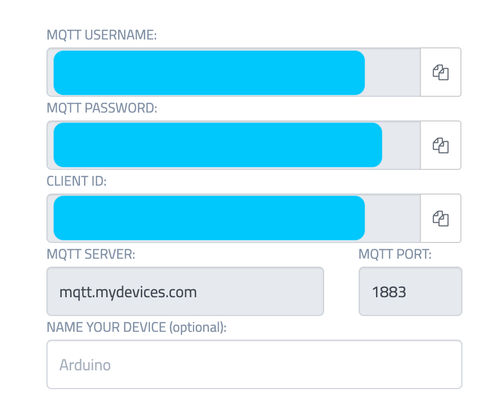
First of all, one is required to sign up and set up an account. Each account has a username, a password. Then your IOT device can be specified and added, each device has its own key. Keep these credentials as they will be required when setting the code up.
The next step is downloading the ESP cayenne on the Arduino IDE. This is not really required but it will save you a lot of time and frustration. The library comes with a ready example for the esp8266 that I am using. The example contains the sending and receiving functions. I based my own code on this, specifying certain input channels that receive sensor data, with others that digitally control a light and a buzzer.
// This example shows how to connect to Cayenne using an ESP8266 and send/receive sample data.
// Make sure you install the ESP8266 Board Package via the Arduino IDE Board Manager and select the correct ESP8266 board before compiling.

//#define CAYENNE_DEBUG
#define CAYENNE_PRINT Serial
#include <CayenneMQTTESP8266.h>

// WiFi network info.
char ssid[] = "ssid";
char wifiPassword[] = "wifiPassword";

// Cayenne authentication info. This should be obtained from the Cayenne Dashboard.
char username[] = "MQTT_USERNAME";
char password[] = "MQTT_PASSWORD";
char clientID[] = "CLIENT_ID";

unsigned long lastMillis = 0;

void setup() {
	Serial.begin(9600);
	Cayenne.begin(username, password, clientID, ssid, wifiPassword);
}

void loop() {
	Cayenne.loop();
}

// Default function for sending sensor data at intervals to Cayenne.
// You can also use functions for specific channels, e.g CAYENNE_OUT(1) for sending channel 1 data.
CAYENNE_OUT_DEFAULT()
{
	// Write data to Cayenne here. This example just sends the current uptime in milliseconds on virtual channel 0.
	Cayenne.virtualWrite(0, millis());
	// Some examples of other functions you can use to send data.
	//Cayenne.celsiusWrite(1, 22.0);
	//Cayenne.luxWrite(2, 700);
	//Cayenne.virtualWrite(3, 50, TYPE_PROXIMITY, UNIT_CENTIMETER);
}

// Default function for processing actuator commands from the Cayenne Dashboard.
// You can also use functions for specific channels, e.g CAYENNE_IN(1) for channel 1 commands.
CAYENNE_IN_DEFAULT()
{
	CAYENNE_LOG("Channel %u, value %s", request.channel, getValue.asString());
	//Process message here. If there is an error set an error message using getValue.setError(), e.g getValue.setError("Error message");
}
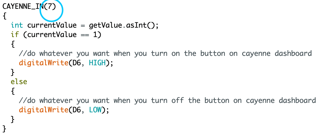
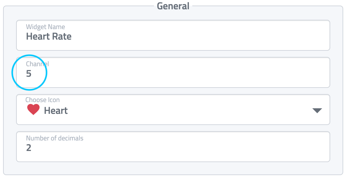
Each I/O corresponds to a channel on cayenne. This channel can be linked to different dashboard widgets to visualize the data or represent a button.
I/O channel code
Widget channel settings
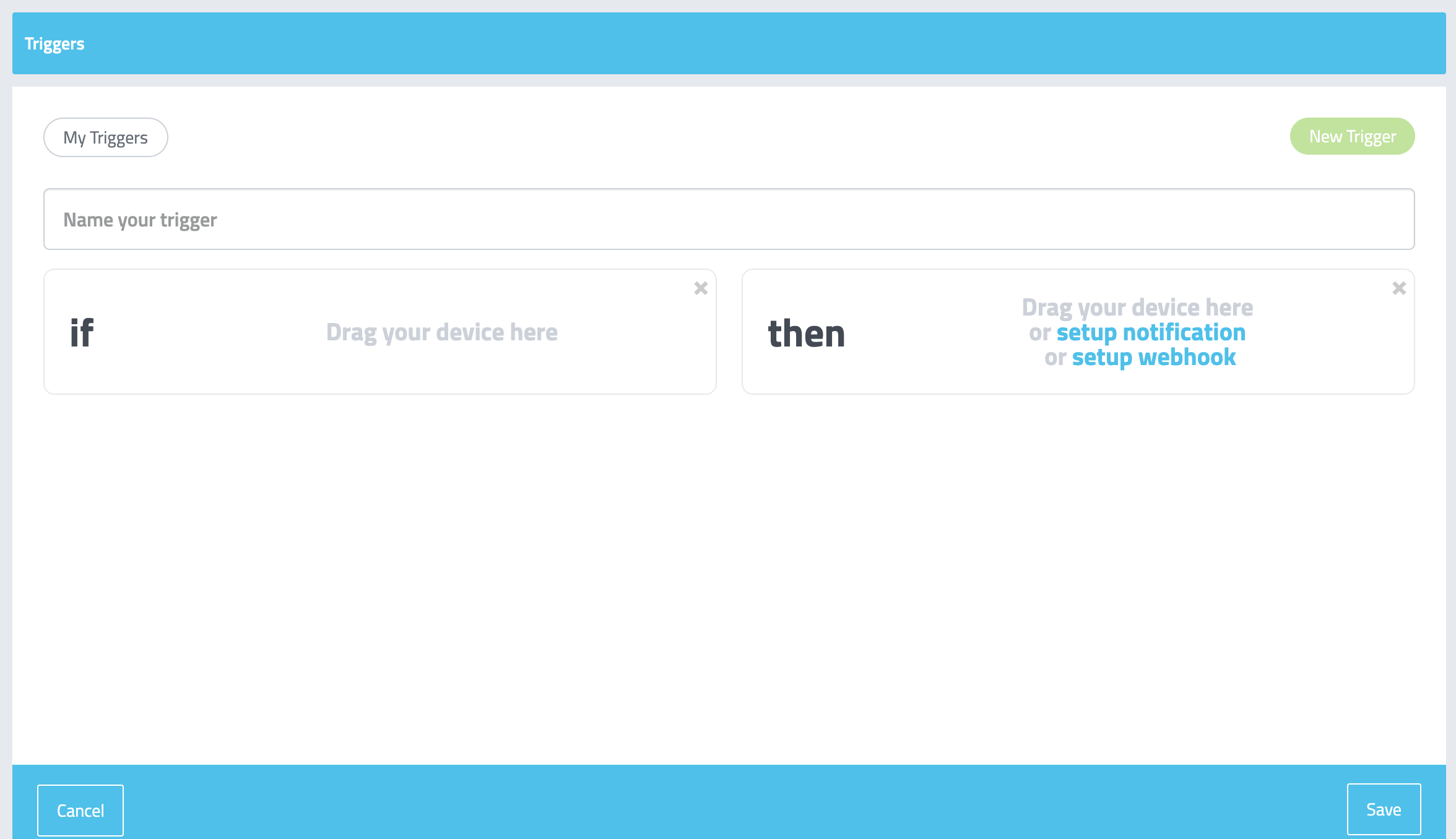
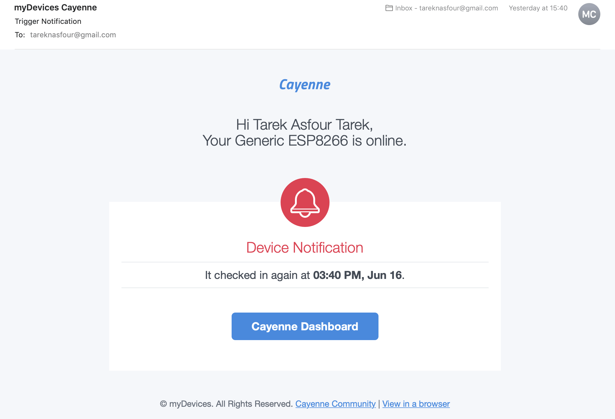
Cayenne also allows the setup of a trigger. This means when a certain value/limit is triggered, a certain action is performed. I used a simple trigger, where as soon as the board is powered in , an email is sent to my email.
Trigger setup
Email notification
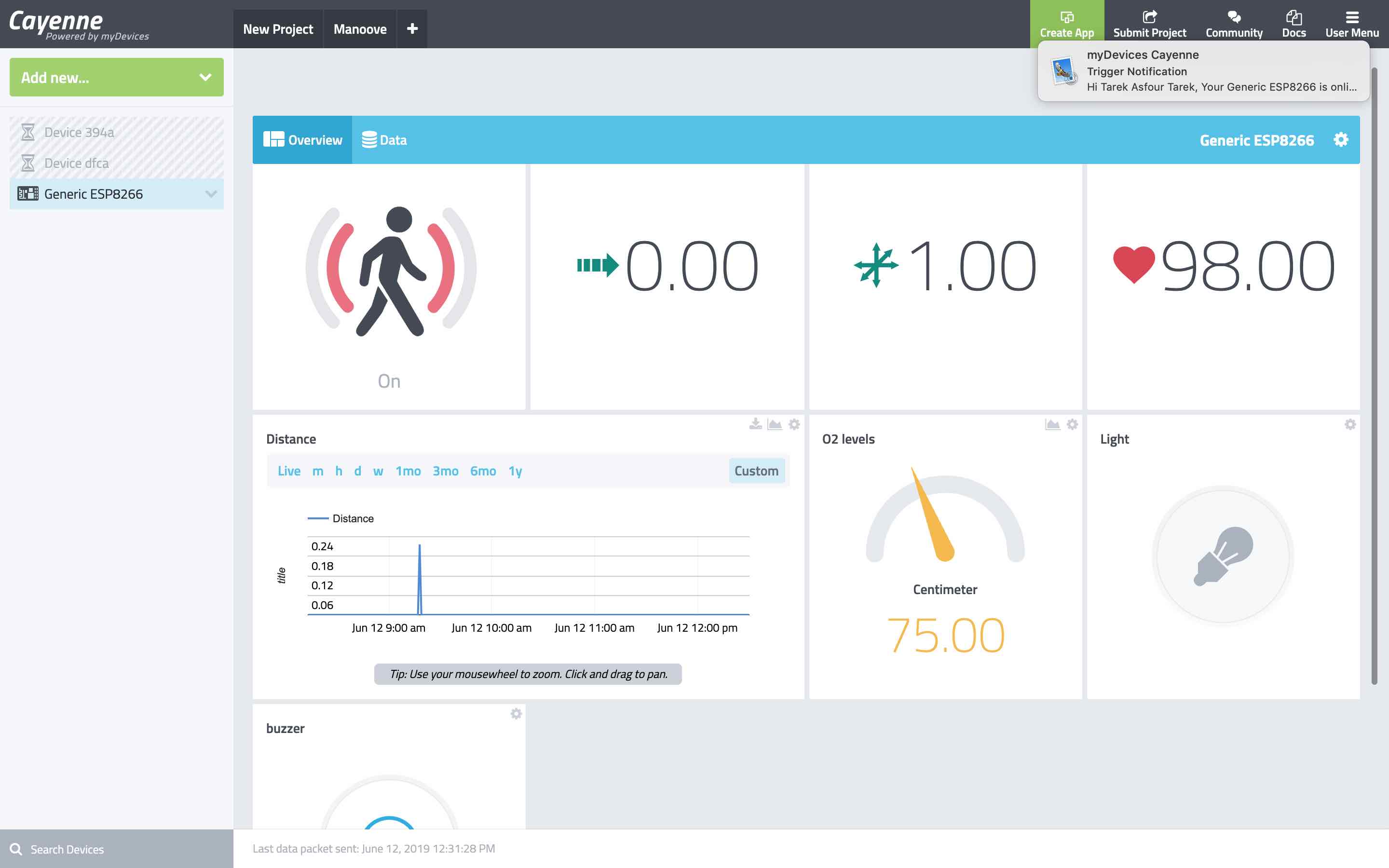
After setting up all inputs and outputs coming from my processing boards, I organized a dashboard to view all the data for my final project. Each widget had a different look to display the data in the most suitable manner.
Files to download
Please find all the files required, if you feel like making your own:
-min.png)