This week focuses on output devices. Output devices can be anything which receives and presents an output of a system. They range from displays, to motors and even printers technically. A while ago, I came across a 7-segment electromechanical driven clock. This caught my attention and I knew I wanted give it a try. The one I saw is a 3D printed clock which uses a raspberry pi and requires printing of 87 pieces for the whole clock. I decided to design a laser-cut single number seven-segment countdown timer, electromechanical display powered by its dedicated designed board. This way I avoid having to use 28 servo motors and wasting a large amount of time and material printing as well as using a cheaper board.
Making the control board
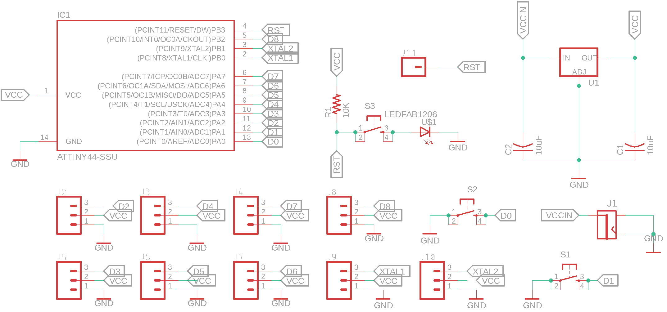
The board I produced for the seven segment electromechanical number display consisted of an Atmel Attiny44 processor, controlling 9 outputs and receiving two pulldowns inputs from push buttons. A reset circuit including an LED and push-button was also included. To save up on space, I also decided to avoid including an ISP header and instead access the pins using the output headers and a single header that was added for the reset circuit. The circuit is powered externally and hence I included a voltage regulator supplying 5V. Below is the circuit schematic.
Initially, I arranged the output headers at angles of 15 degrees to eachother along a circular path. This was done to allow for easy distribution. I also used the curved routing feature, specifying a higher radius to produce the shape of the tracks I wanted
When it came to the distribution of the rest of the components, I attempted a few different placements before I reached the most efficient one. I was in Jordan's seaside city, Aqaba, this weekend, and after a day of swimming surrounded by jellyfish, I came back to continue the board design. It just happened that the component placement resembled a jellyfish's body, and so I added the tentacles in the cutting outline to complete the shape.
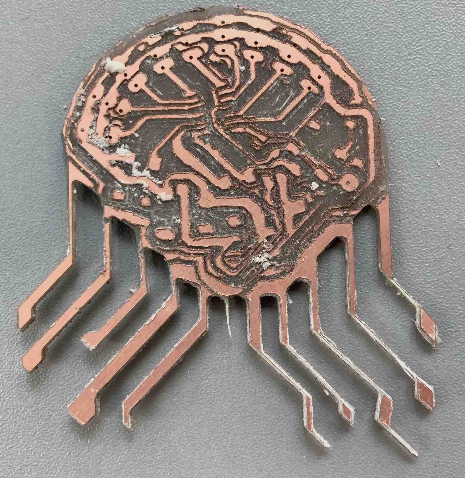
The next step was milling the board. I initially tried using a damaged 1/64 inch endmill, but as can be seen in the picture it was way to damaged to produce a functional result, many traces weren't cut while others were wrongfully removed. The outline cut was done using a 1/8 endmill and unfortunately, it also cut some of the tentacles in the design too slim. Since there were no more 1/64 inch endmills and the new shipment was still stuck in customs, I had to use a V-shaped 0.4mm tip endmill for milling of the next attempt.
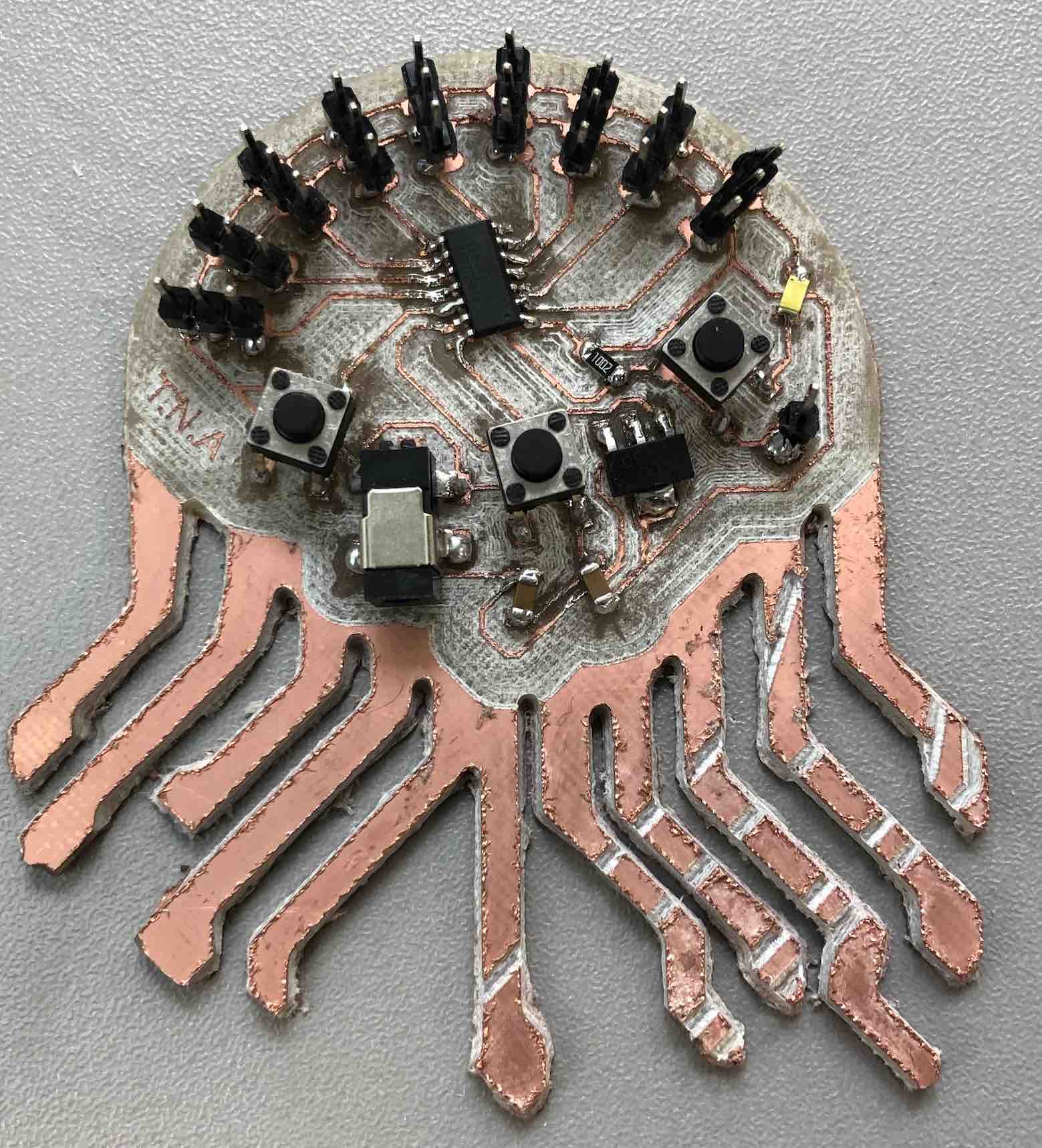
The result produced by the V-shaped endmill was rather rough but all traces were there and the board was functional. I drilled the holes for the headers using a 0.2mm drilling endmill. The outline cut was done using a 1/16 inch flat endmill to ensure all the details of the tentacles were intact. After cleaning the board with alcohol, I soldered on the components on their pads and this was the final result.
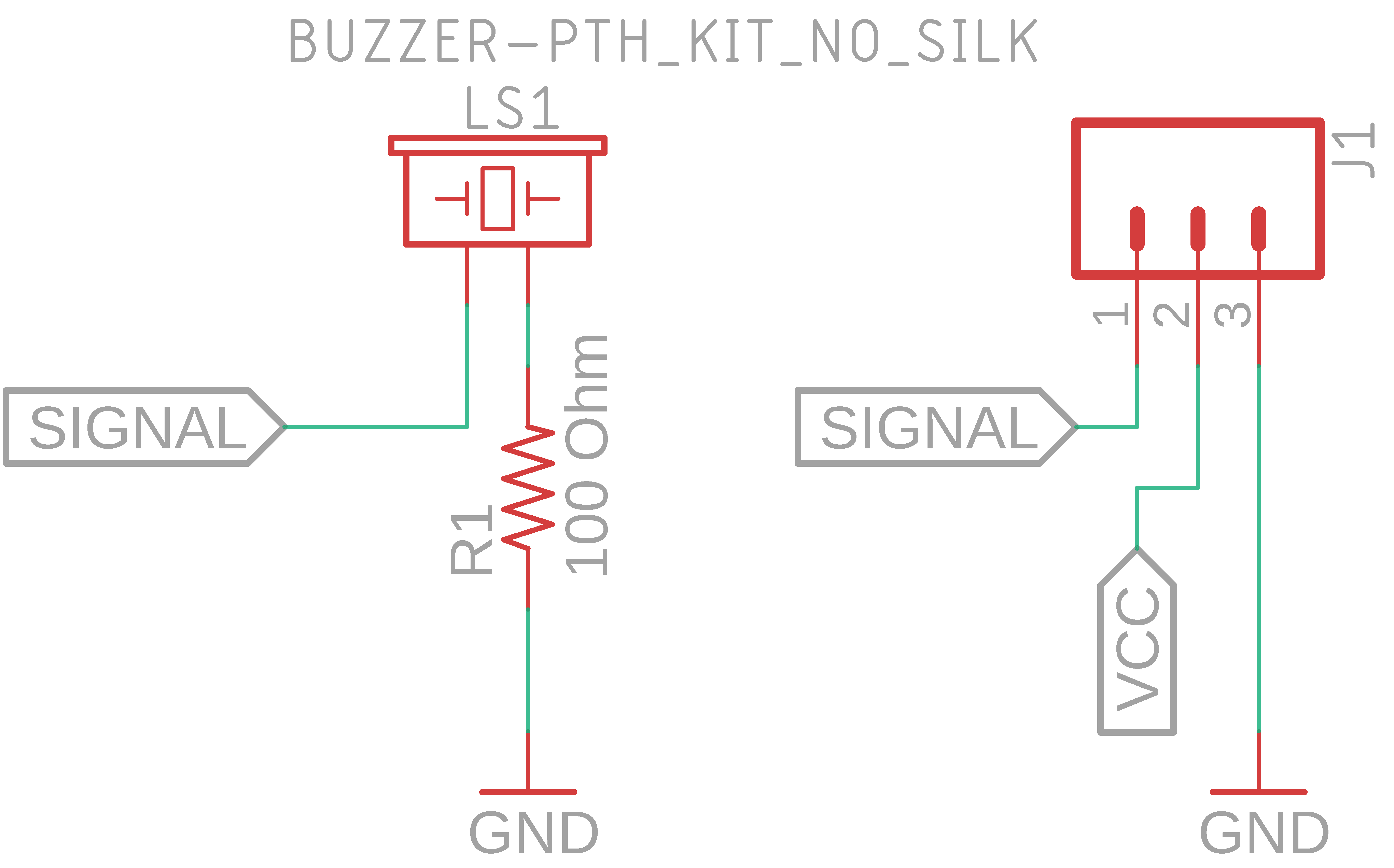
Afterwards, I decided to add a buzzer and luckily the board was modular, so I just had to make a breakout board hosting the buzzer. It was a very simple board, and since my first board was a jellyfish, I stuck with the theme and made it into a fish shape. For fabrication I used the same tools and settings used for the previous board.
Buzzer schematic
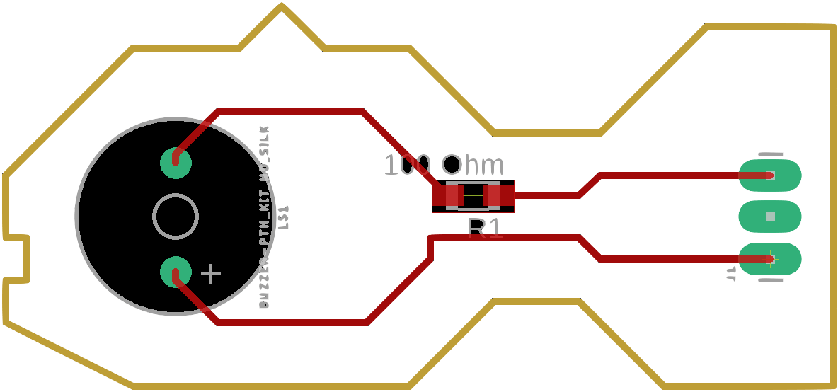
Buzzer routing
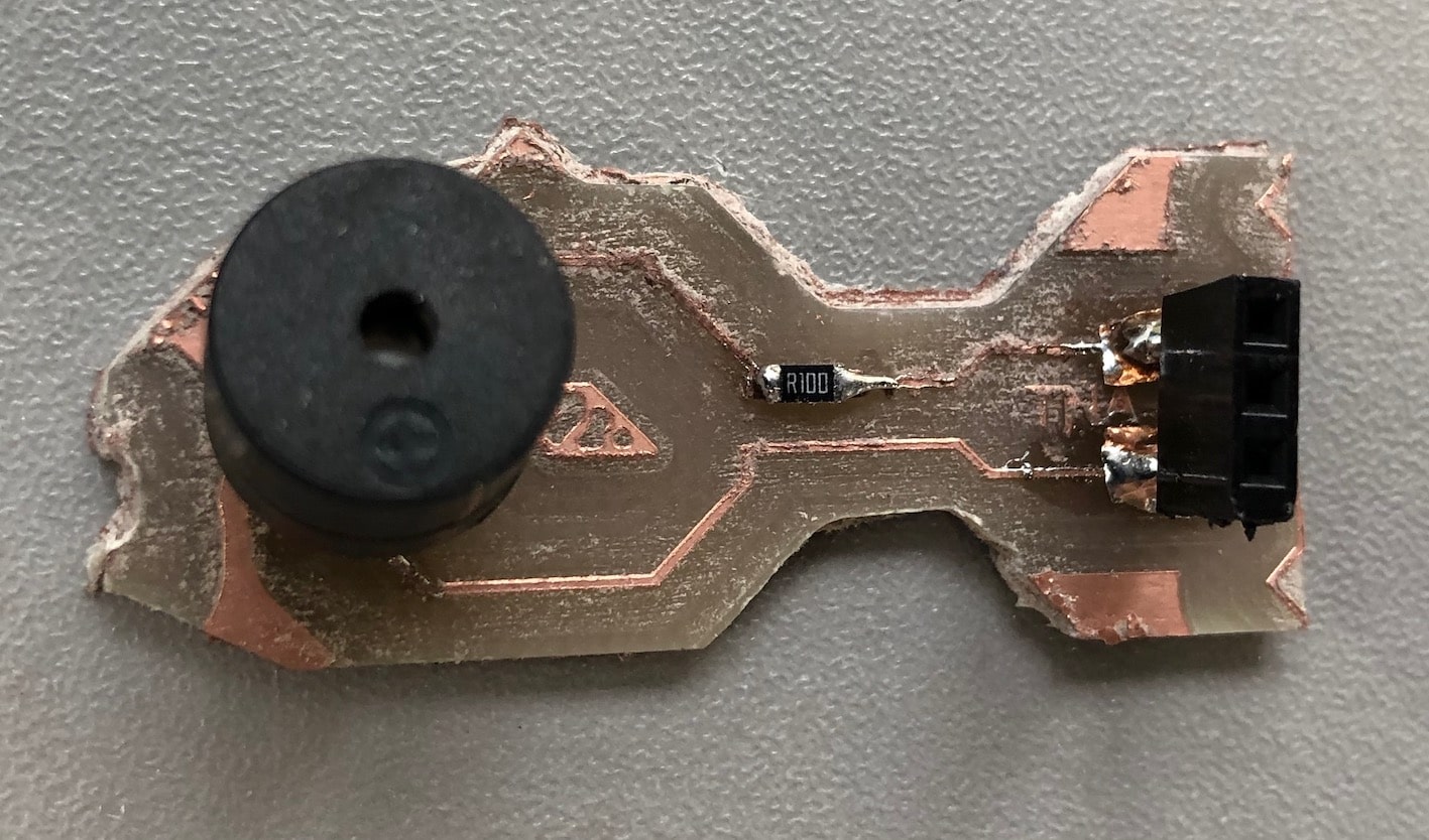
Buzzer board
Building the case
To fix the servos in the correct position and create an aesthetic product, I wanted to fabricate fast prototyped housing. I therefore chose to lasercut the housing case using scrap acrylic we had in the lab to minimize the environmental impact of the product, especially since I got the inspiration for my boards design from the sea.
The box base was a simple rounded edge rectangle with openings for the servo motor brackets. The servo brackets are designed to snap and lock in place. This is not enough to secure the servo, but it serves the purpose of ensuring the correct placement. Double-face tape was used to fix the servos in place.
The sides were designed and fabricated from a single piece of acrylic. I used the kerf designed previously tested during to create the corner bends. Along the longer edges I included a hole on each side to pass wires through. A hexagonal pattern design was engraved for aesthetic purposes
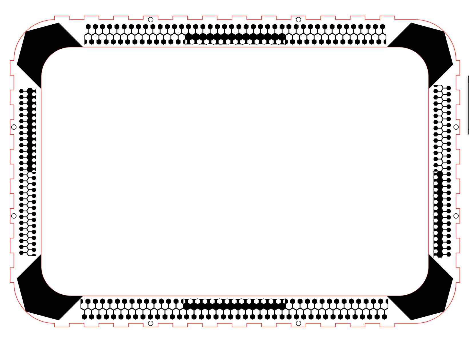
The top piece was composed of two pieces, an opaque border top cover with a hollowed center and a clear transparent middle cover, with engraved designs that are made to block out the interior of the product, other than the presented segments. I experimented with an interesting technique; I achieved 2.5D functional properties engraving at a slower speed and higher power (100% PWR and 25m/s velocity as I was using 3mm acrylic). This allowed me to create a profile in which the clear top piece fits in. Ofcourse, aesthetic computer generated and geometric hexagonal patterns were added to maintain consistency aesthetically.
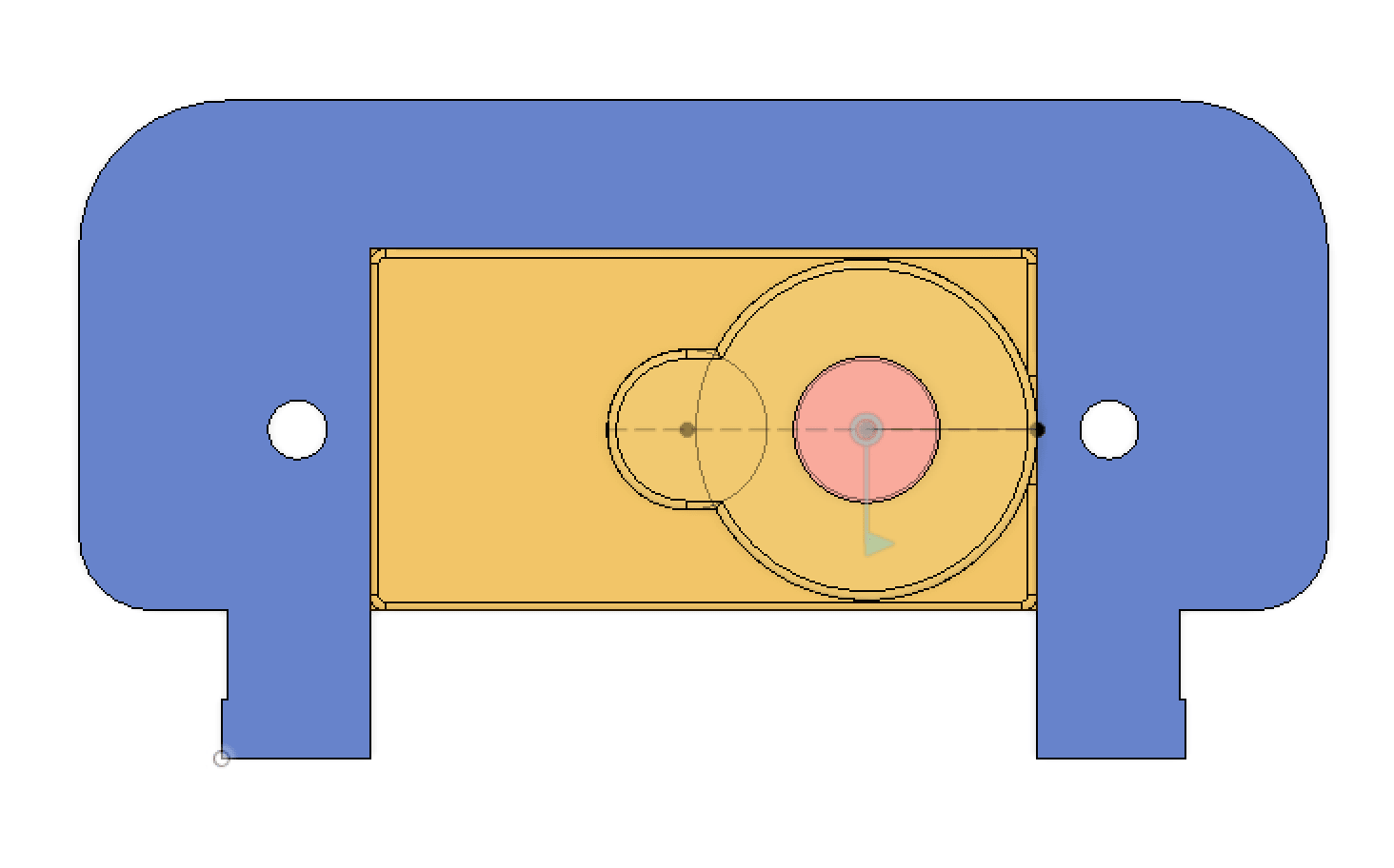
Top Design
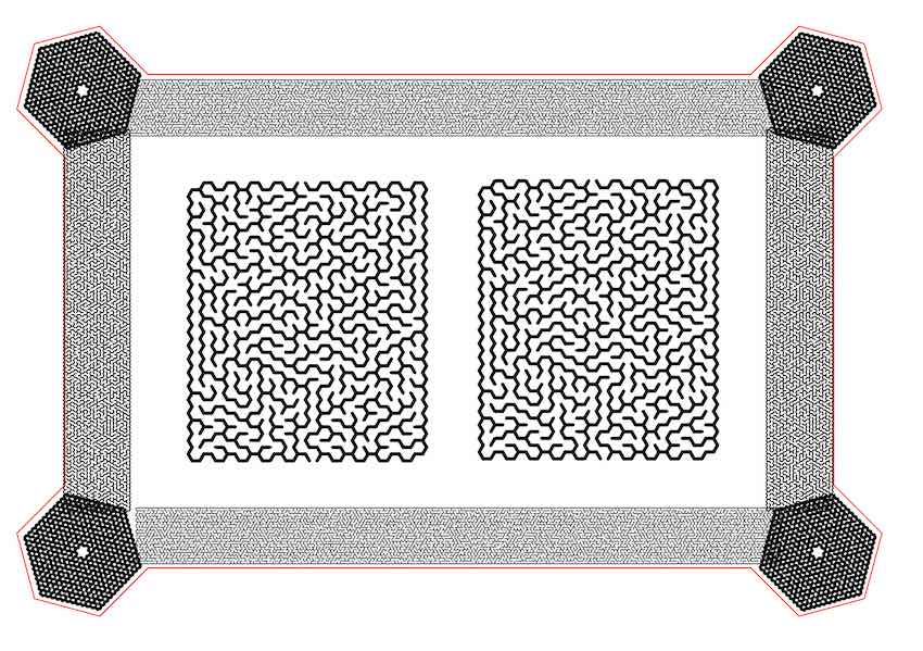
Bottom Design
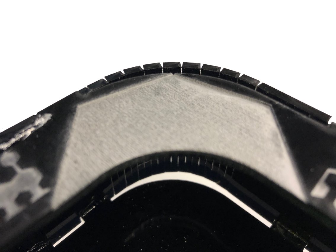
2.5D engraving
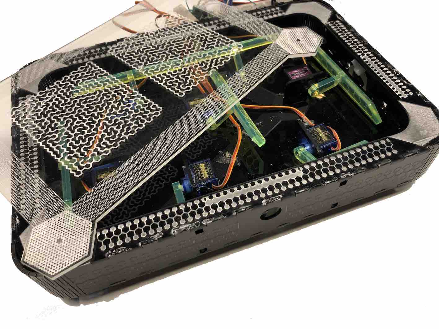
I laser-cut and assembled all pieces of the housing. Since the kerf wasn't 100% press-fit and I wanted a more rugged product, I had to resort to using some super glue to ensure the joints are fixed. I used zip-ties as feet, by tightly inserting them through the gaps left between the bottom base and side piece. The product was pretty impressive for an initial quick prototype.
Connecting and programming the buzzer
I decided to use a buzzer along with the servo motors, as I will use be including an alarm in my final project. The servo was initially connected directly to an Arduino Uno signal pin and ground including a 100 Ohm resistor. This setup was used to test the alarm frequency that I will be using. I finally settled on an iterative loop that incrementally increases the frequency and after a cutoff frequency incrementally decreases the frequency in a loop.
        //initialize variables
const int buzzer = 4;
int incrementfreq = 100;
int delayval = 10;
int interval = 100;
int deccutoff = 1500;
int inccutoff = 1500;
int startinc = 500;
int startdec = 2200;

void setup() {
  // put your setup code here, to run once:
  //setup buzzer pin
pinMode(buzzer,OUTPUT);
}

void loop() {
  // put your main code here, to run repeatedly:
int i = startinc; // starting pitch of increasing loop
  while(i < inccutoff) {
    i=i+incrementfreq;// increment
    tone(buzzer, i); // Emit the noise
    delay(delayval);
  }
  delay(interval); // A short break in between each whoop
  int k = startdec; // starting pitch of decreasing loop
  while(k > deccutoff) {
    k=k-incrementfreq;
    tone(buzzer, k); // Emit the noise
    delay(delayval);
  }
}
Programming the servos
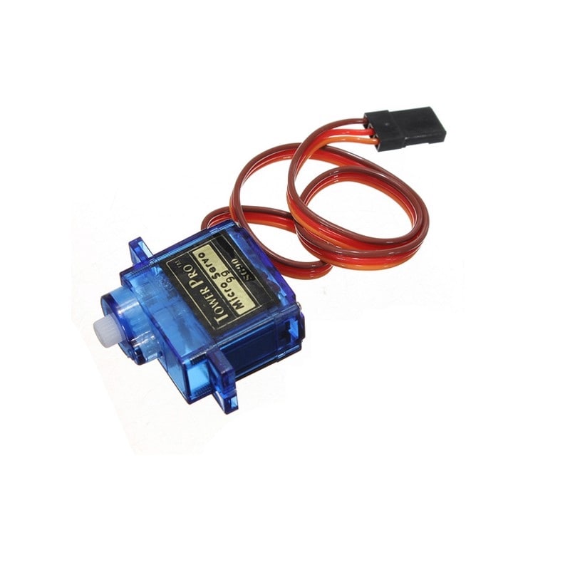
The servos I will be using are 180 degree micro-servos, with just enough torque and angular control capabilities for moving a small piece of acrylic less than 90 degrees. They are connected by 3 wires (VCC, GND and signal). The signal to control servos is similar but not particularly pulse-width modulation. This means that to communicate to servos, one isn't constrained to solely the PWM pins. The arduino servo library has the ability to produce the required pseudo PWM signal either by setting the degree or microseconds per pulse.
The servo code was developed simultaneously with the control PCB production, so the code was initially tested on an Arduino Uno and then modified and implemented on the Attiny44 control board. The code development went through 3 major stages. The first was finding the lower and upper limit for each servo segment. This was done using the arduino servo I used the code shown on the right to achieve this by changing the microseconds value
             #include <Servo.h>
Servo servo;
void setup() {
  // put your setup code here, to run once:
servo.attach(4);
}

void loop() {
  // put your main code here, to run repeatedly:
servo.writeMicroseconds(2000);
delay(1000);
}
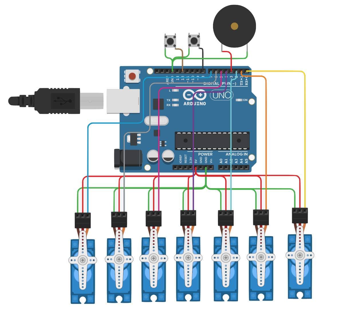
The next step was writing the countdown timer code. Since the board was still in production, I simulated the code on tinkercad. I moved the motors with a 1000 millisecond delay between each move to achieve the relative timing. I also included a beep and the siren noise written in the previous section to have the buzzer work simultaneously within the same code. I included two buttons, one for restarting the timer and one for starting.
This is the final tested code:
//initialize servo library and servos
#include <Servo.h>
Servo topcenter;
Servo topright;
Servo topleft;
Servo center;
Servo bottomright;
Servo bottomleft;
Servo bottomcenter;

//initialize variables
int const buttonstart = 8;
int const buttonreset = 12;
int currentstate = 0;

//initialize buzzer variables
//initialize variables
const int buzzer = 10;
int incrementfreq = 100;
int delayval = 10;
int interval = 100;
int deccutoff = 1500;
int inccutoff = 1500;
int startinc = 500;
int startdec = 2200;
int beeptone = 3500;
int sirenrep = 0;

//initialize servo parameters
int const traise = 1800;
int const tlower = 1000;
int const trraise = 1700;
int const trlower = 1000;
int const tlraise = 1400;
int const tllower = 1000;
int const craise = 1900;
int const clower = 1500;
int const brraise = 1900;
int const brlower = 1000;
int const blraise = 1700;
int const bllower = 1000;
int const braise = 2000;
int const blower = 1200;

void setup() {
  // put your setup code here, to run once:

 //setup button setup
 pinMode (buttonstart, INPUT_PULLUP);
 pinMode (buttonreset, INPUT_PULLUP);
 pinMode (buzzer, OUTPUT);


 //Attach servos
topcenter.attach(9);
topright.attach(3);
topleft.attach(2);
center.attach(4);
bottomright.attach(5);
bottomleft.attach(6);
bottomcenter.attach(7);

//Return to home
topcenter.writeMicroseconds(tlower);
topright.writeMicroseconds(trlower);
topleft.writeMicroseconds(tllower);
delay(20);
bottomleft.writeMicroseconds(bllower);
bottomright.writeMicroseconds(brlower);
bottomcenter.writeMicroseconds(blower);
delay(100);
center.writeMicroseconds(clower);
delay(100);
    currentstate==3;
    }

void loop() {
  // put your main code here, to run repeatedly:

  if (digitalRead(buttonreset)==0){
    //Go to 9
    center.writeMicroseconds(craise);
    delay(100);
    topcenter.writeMicroseconds(traise);
    bottomcenter.writeMicroseconds(braise);
    delay(50);
    topright.writeMicroseconds(trraise);
    topleft.writeMicroseconds(tlraise);
    bottomright.writeMicroseconds(brraise);
    delay(50);
    currentstate=2;
    }

 if (currentstate==2 && digitalRead(buttonstart)==0){

 // Go to 8
 currentstate=0;
 delay(800) ;
bottomleft.writeMicroseconds(blraise);
tone(buzzer, beeptone);
delay(50);
noTone(buzzer);


//Go to 7
delay(950);
topleft.writeMicroseconds(tllower);
bottomleft.writeMicroseconds(bllower);
bottomcenter.writeMicroseconds(blower);
delay(100);
center.writeMicroseconds(clower);
tone(buzzer, beeptone);
delay(50);
noTone(buzzer);


//Go to 6
delay(850);
topright.writeMicroseconds(trlower);
delay(50);
center.writeMicroseconds(craise);
delay(50);
topleft.writeMicroseconds(tlraise);
bottomleft.writeMicroseconds(blraise);
bottomcenter.writeMicroseconds(braise);
tone(buzzer, beeptone);
delay(50);
noTone(buzzer);


//Go to 5
delay(850);
bottomleft.writeMicroseconds(bllower);
delay(100);
tone(buzzer, beeptone);
delay(50);
noTone(buzzer);


//Go to 4
delay(850);
topcenter.writeMicroseconds(tlower);
bottomcenter.writeMicroseconds(blower);
delay(100);
topright.writeMicroseconds(trraise);
tone(buzzer, beeptone);
delay(50);
noTone(buzzer);


//Go to 3
delay(850);
topleft.writeMicroseconds(tllower);
delay(100);
bottomcenter.writeMicroseconds(braise);
topcenter.writeMicroseconds(traise);
tone(buzzer, beeptone);
delay(50);
noTone(buzzer);


//Go to 2
delay(850);
bottomright.writeMicroseconds(brlower);
delay(100);
bottomleft.writeMicroseconds(blraise);
tone(buzzer, beeptone);
delay(50);
noTone(buzzer);


//Go to 1
delay(850);
topcenter.writeMicroseconds(tlower);
bottomleft.writeMicroseconds(bllower);
bottomcenter.writeMicroseconds(blower);
delay(50);
center.writeMicroseconds(clower);
delay(50);
bottomright.writeMicroseconds(brraise);
tone(buzzer, beeptone);
delay(50);
noTone(buzzer);

//Go to 0
delay(850);
topcenter.writeMicroseconds(traise);
topleft.writeMicroseconds(tlraise);
bottomleft.writeMicroseconds(blraise);
bottomcenter.writeMicroseconds(braise);
delay(100);
currentstate=1;
tone(buzzer, beeptone);
delay(50);
noTone(buzzer);
  }

   if (currentstate==1 && sirenrep<30){
    //ring buzzer
    int i = startinc; // starting pitch of increasing loop
  while(i < inccutoff) {
    i=i+incrementfreq;// increment
    tone(buzzer, i); // Emit the noise
    delay(delayval);
  }
  delay(interval); // A short break in between each whoop
  int k = startdec; // starting pitch of decreasing loop
  while(k > deccutoff) {
    k=k-incrementfreq;
    tone(buzzer, k); // Emit the noise
    delay(delayval);
    noTone(buzzer);

    sirenrep++;
  }
//Return to home
topcenter.writeMicroseconds(tlower);
topright.writeMicroseconds(trlower);
topleft.writeMicroseconds(tllower);
delay(20);
bottomleft.writeMicroseconds(bllower);
bottomright.writeMicroseconds(brlower);
bottomcenter.writeMicroseconds(blower);
delay(100);
center.writeMicroseconds(clower);
delay(100);

    currentstate==3;
    }
}
Once the code simulation was working on tinkercad the next step was testing it on an Arduino Duemilanove we had as it had male headers dedicated for servo connections. This made it easier to check the servos before connecting my board (since I wasnt 100% sure my board was functioning). This step worked well and below is a video of it in action!
Testing it with own board
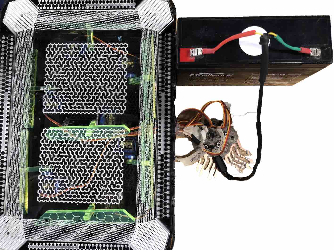
The last step was to test the setup with the dedicated "jelly board. The board required uploading of the bootloader and a few tweaks of the code by changing the pin numbers that were used on the arduino to the pins that correspond with the integrated servo headers of the output board. I made a battery connector by using a crimping tool to attach the battery connector and some heatshrink tubing. This allowed me to connect the board directly to a 6V battery.
Here is my hero video with the whole assembly working. Unfortunately, I came to do this weeks after I worked on this project and some components were not working. One of the servo motors had a broken gear and the center segment piece was broken. More importantly it looks like my attiny chip was faulty and the board wasn't working. So I decided to use my atmega board, the byrduino in addition to a breadboard to make the connections easier, since they are female to female. The timer work but wasn't optimal.
Files
Please find all the files required, if you feel like making your own:
-min.png)