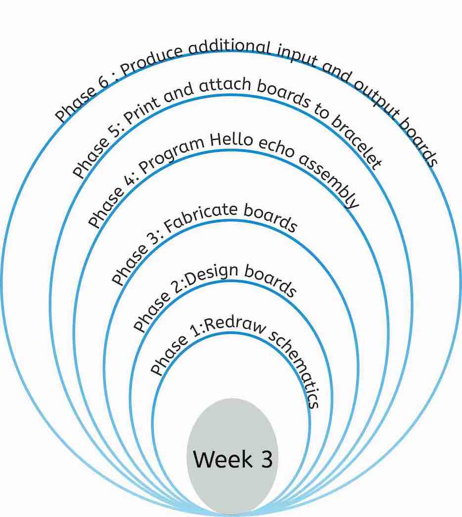
During this week our objective was to redraw a hello echo board and program it with atleast one input and one output. I came up with an interesting way of applying these concepts. I wanted to create a modular board with interchangable input and output boards. Then, I wanted to encase this design in a 3D-printed bracelet. Initially, my main goal is to design and fabricate one processing board with one input and one output board. Depending how much time I have left, I will design and produce more modular inputs and outputs.
Designing the circuit schematic
To redraw the hello echo board, I started with the provided schematics and redrew each section of the board individualy. This was done to make understanding the board easier as well as seperating the input/output from the main board. I did this step on Autodesk's electronic's design software Eagle, which would later allow me to use the same schematic to route the tracks and design the board's shape. I have specified the exact steps below.
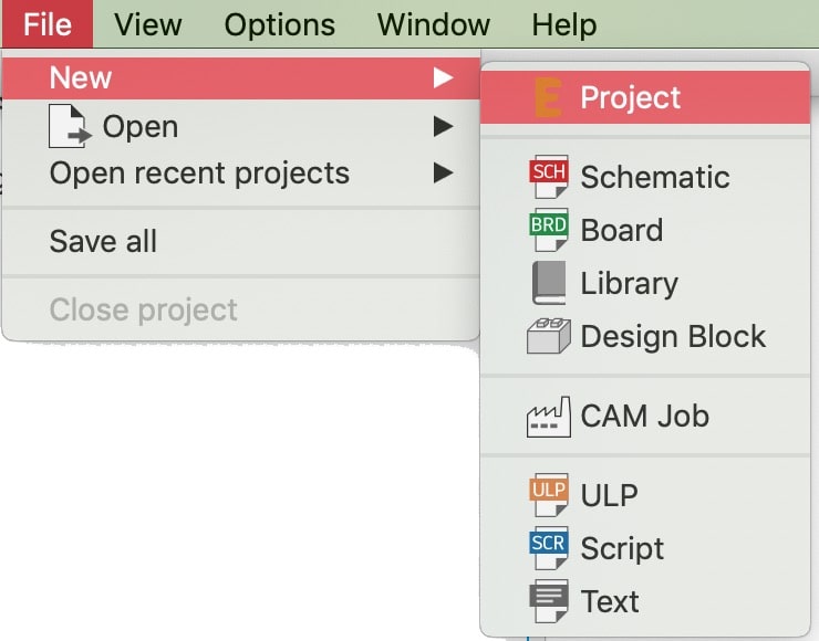
To start using Eagle with the available components, I downloaded the . Before continuing with the library setup, I created a new project and named it "Hello_echo", which created a directory that will contain all electronic-related files created this week. To do this go to File > New > Project. After creating the project, I copied the downloaded files to the libraries folder in Eagle's directory, and then proceeded to install it on Eagle by choosing open library, accessed from the library tab in the toolbar above.
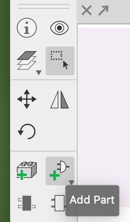
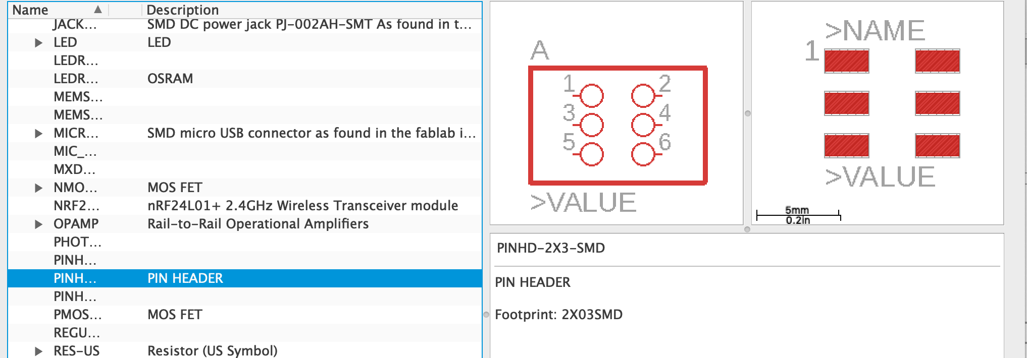
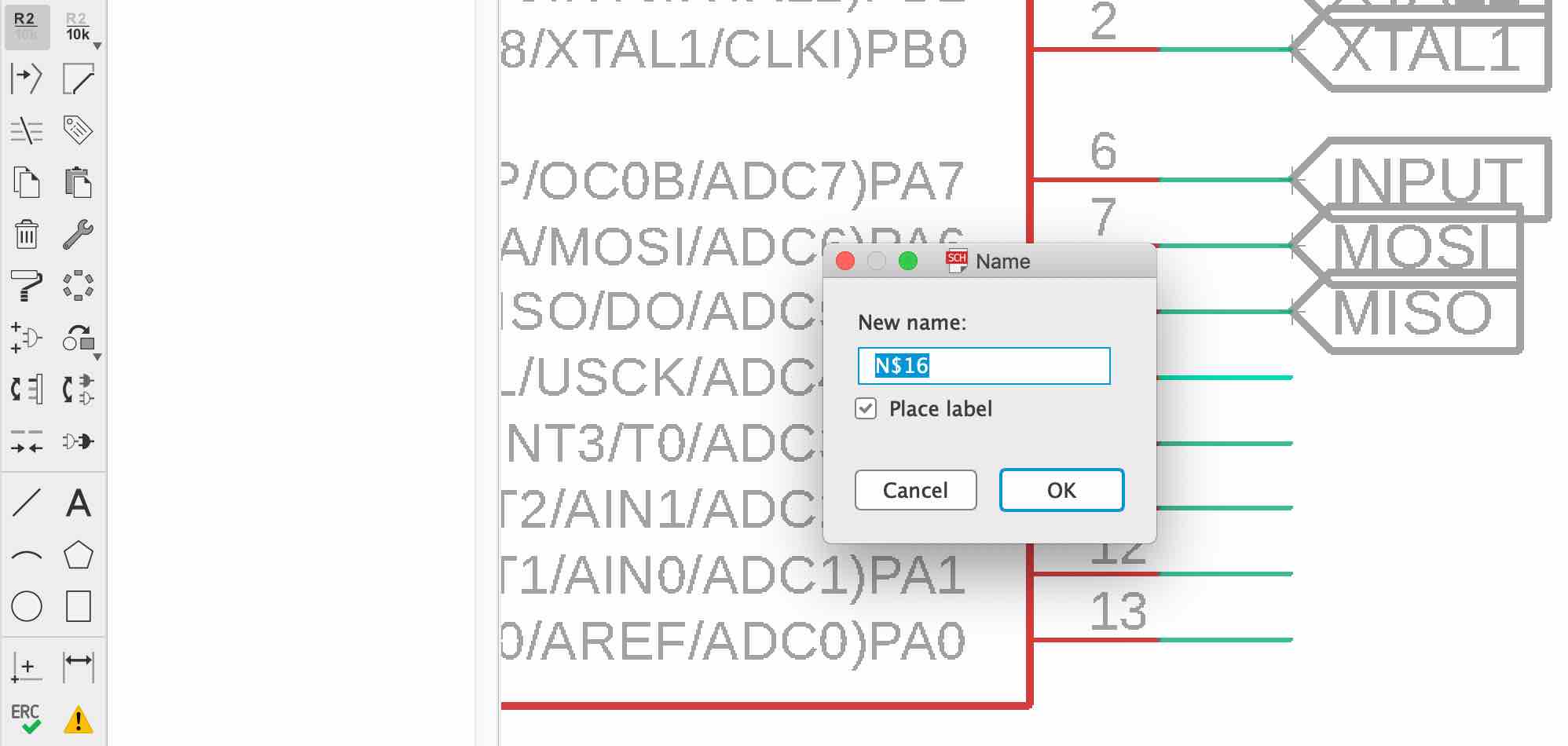
To start designing click on the add part button. The window shown on the right pops up, through which you can choose the required part. The parts can then be connected using the netting tool.
To maintain an organized design. I added labels to nets coming out of the main components, in order to seperate parts of the circuit. Basically you add a label to one end, and when an identical label is added to the other end, this window pops up to confirm the netting link.
After checking all connections I had the schematic I will be using to design the board routing and shape.
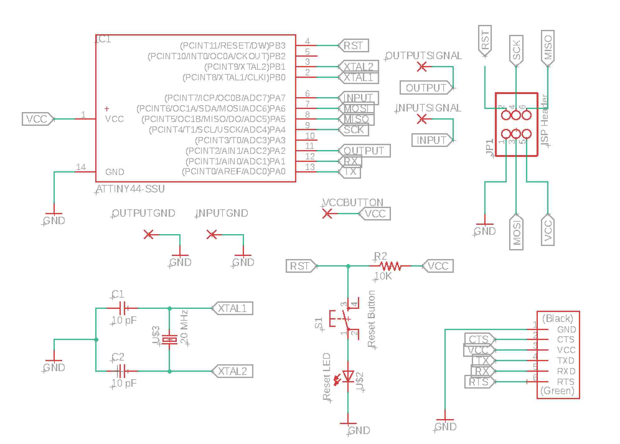
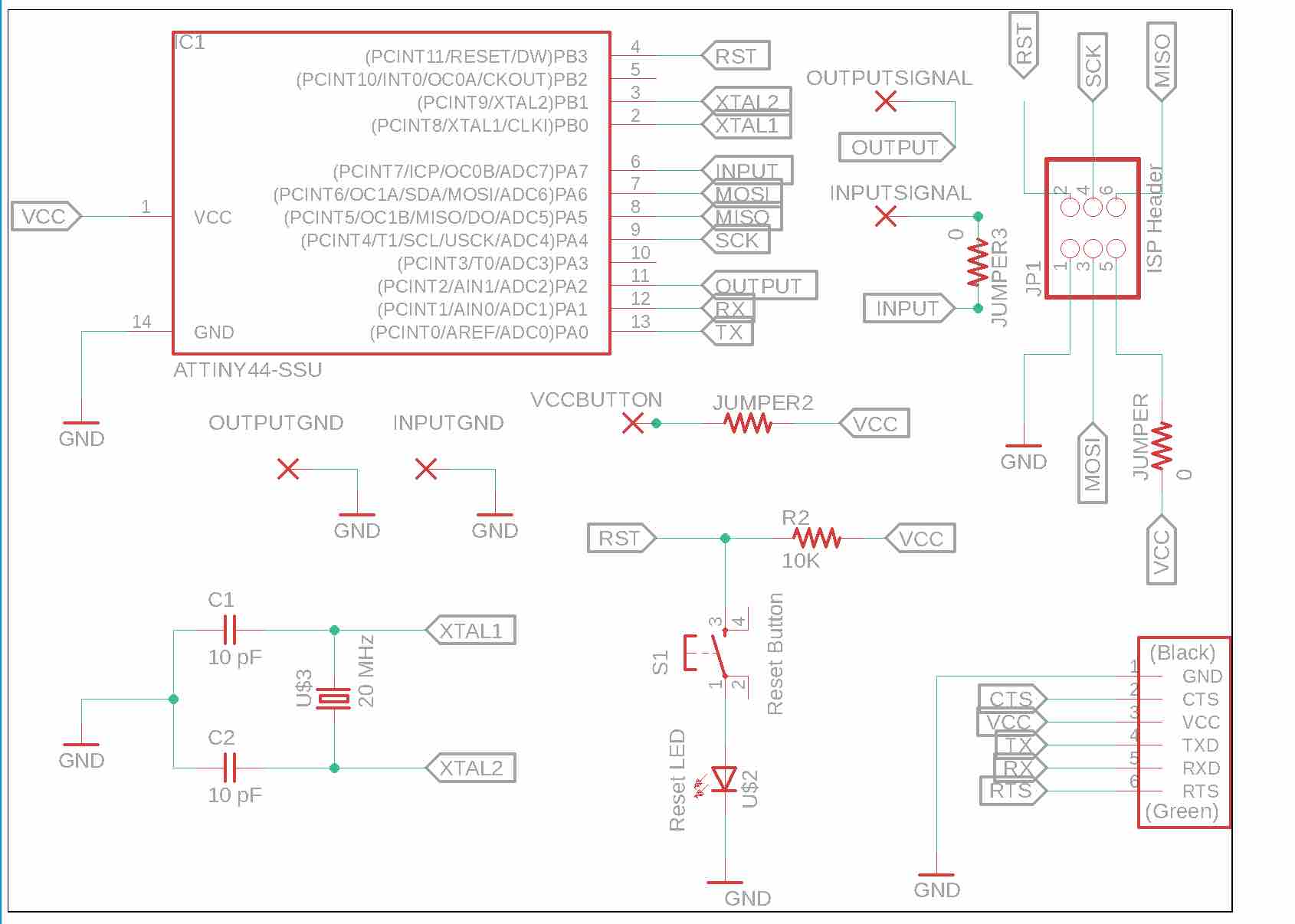
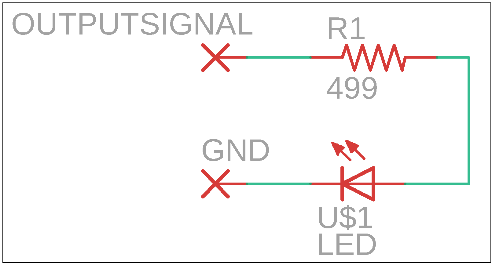
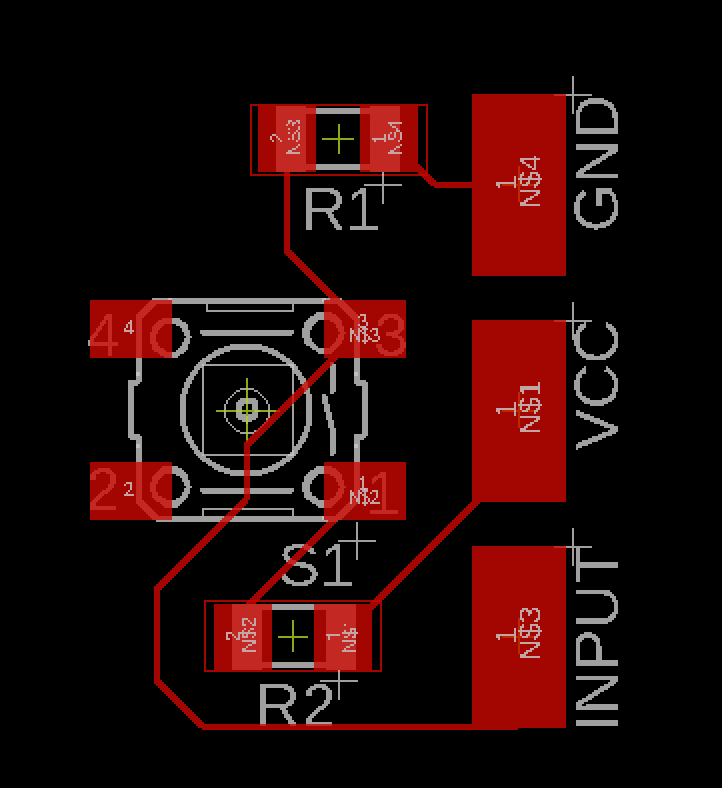
Since the main board schematic was changed in the design phase to add jumpers, 0 Ohm resistors, below is the updated schematic along with the schematics for the button and LED.
Main board schematic
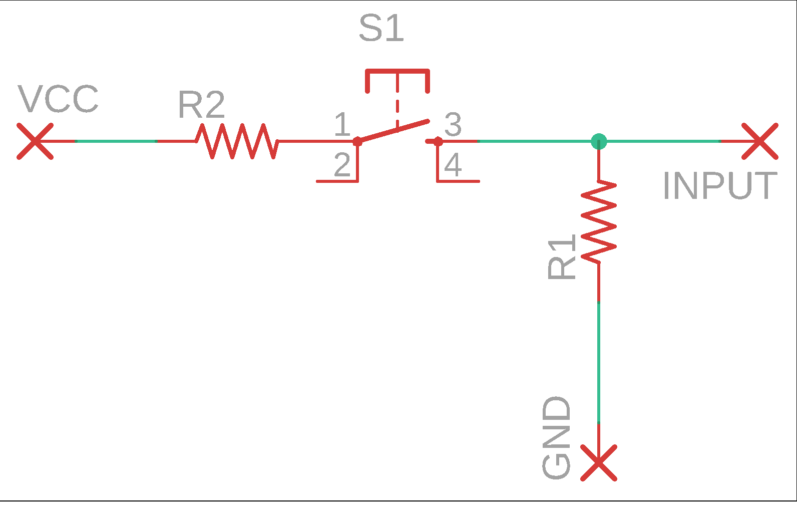
Button input schematic
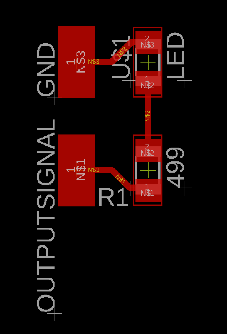
LED output schematic
Routing the tracks
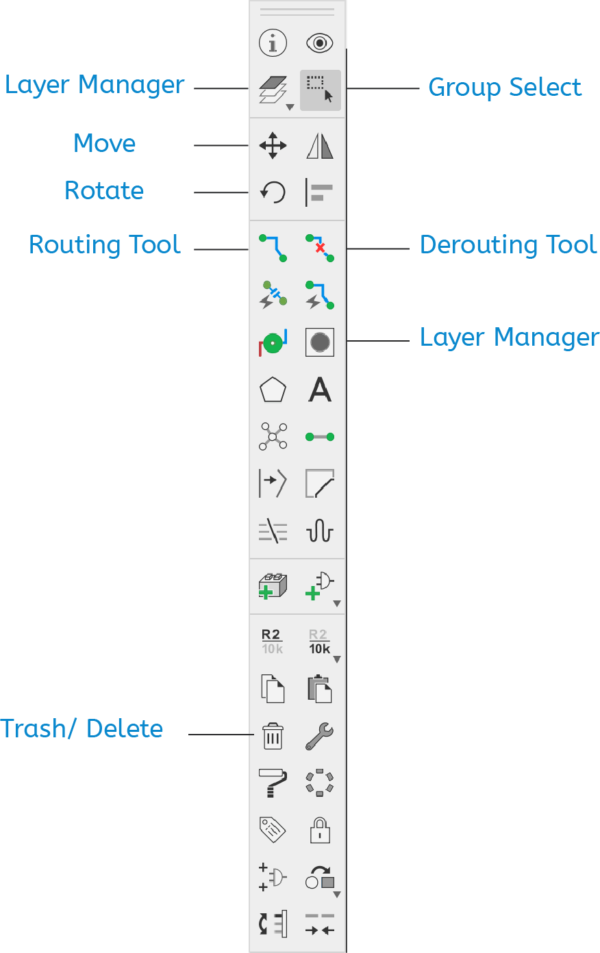
When switching to the board design viewer. The toolbar contains tools such as move and rotate that are used to specify the placement of components and tracks. There is also a delete button to delete any uneeded components or holes, etc... After placing the components I used the routing tool to set up the track paths. If anything was routed incorrectly, simply use the unrouting tool to delete part of that track.
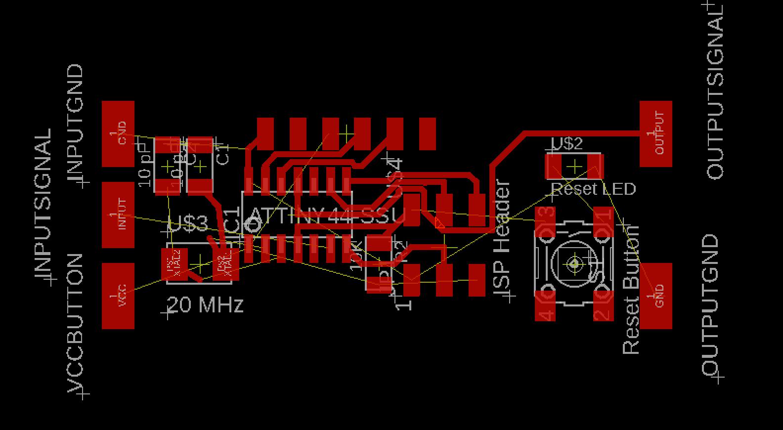
Automatically the components show up with yellow lines indicating linked components. These linked tracks can be organized using the rats nest command, which slightly organized the lines after rotating and moving the components around. I attempted to initially route the components without using any jumpers but it wasn't possible given the particular setup I had with the two connections on each side and the constrained size of the board. I therefore included two zero ohm resistors, acting as a bridge and allowing tracks to run under them.
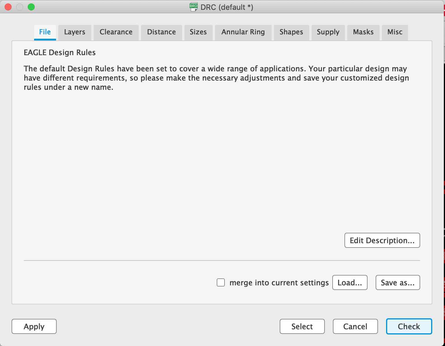
The board design looked good and now I had to check if it met all the design rules. I downloaded the design rules , and from the tools menu chose DRC. The window to your right shows up, through which I clicked on load and specified the location of the downloaded design rules file. I then ran the check and a few errors came up.
As seen on the right there were a number of clearence errors. I was able to solve all except for the one shown on the left as it was running under header pins. I therefore decided to go back to the schematics and a 0 Ohm reisistor then reroutedd one of the tracks from above.
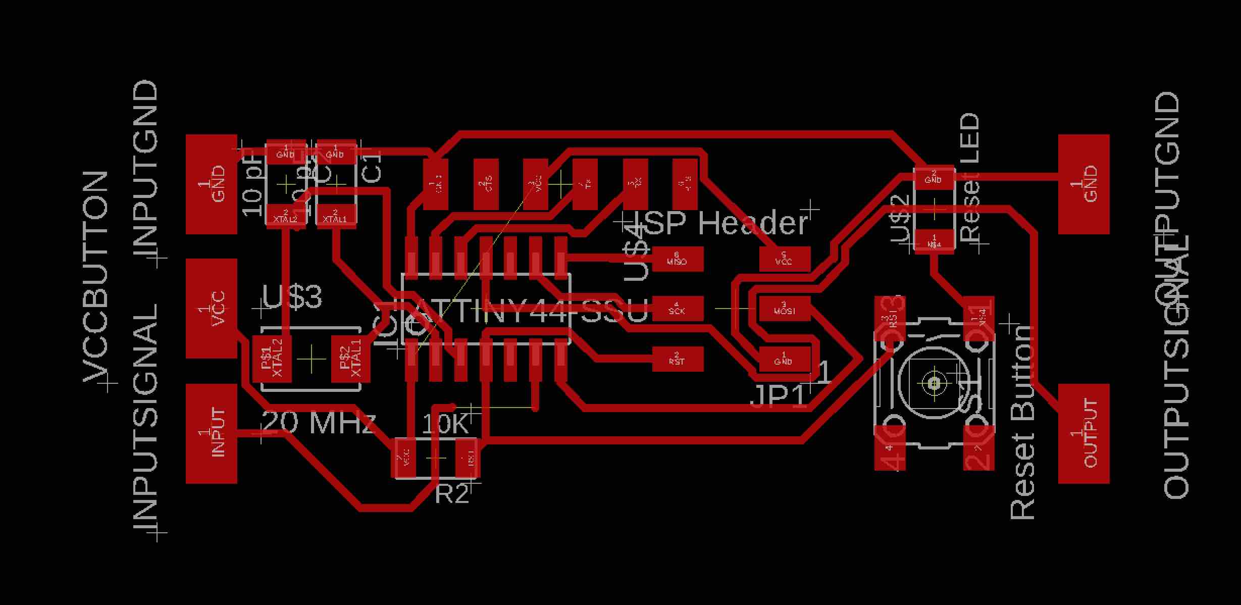
After some time, and several design rule checks, I had three board designs for my hello echo and was ready to move to the fabrication stage.
Main board
Button input board
LED output board
Board Fabrication
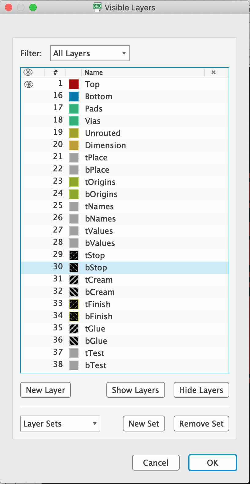
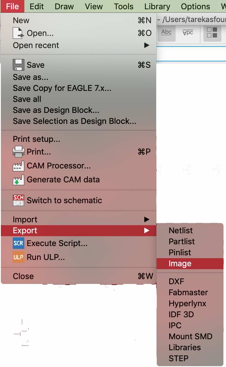
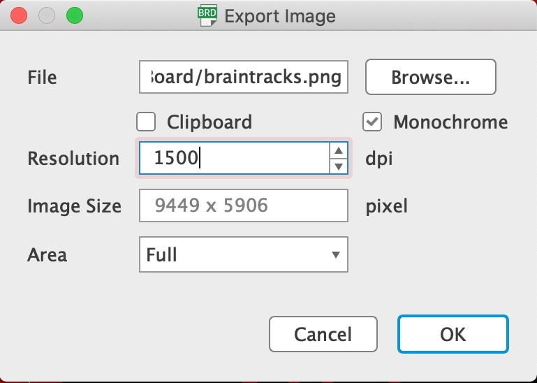
To fabricate the board the process first entailed me to mill the tracks on the Roland SRM-20, solder the components on, then solder the boards to eachother. In order to send the designs to the milling maching, I had to output seperate images of the track designs and the cutting dimensions. To do this, click on the layer manager and select hide layers. Once that is done show the top and pads layer, to view the tracks on their own. Then click on file export, then image to export the track design as an image. It is important to specify the resolution, 1500, as it will be needed when processing the job on FabModules. Also, check the monochrome box to produce a black and white image.
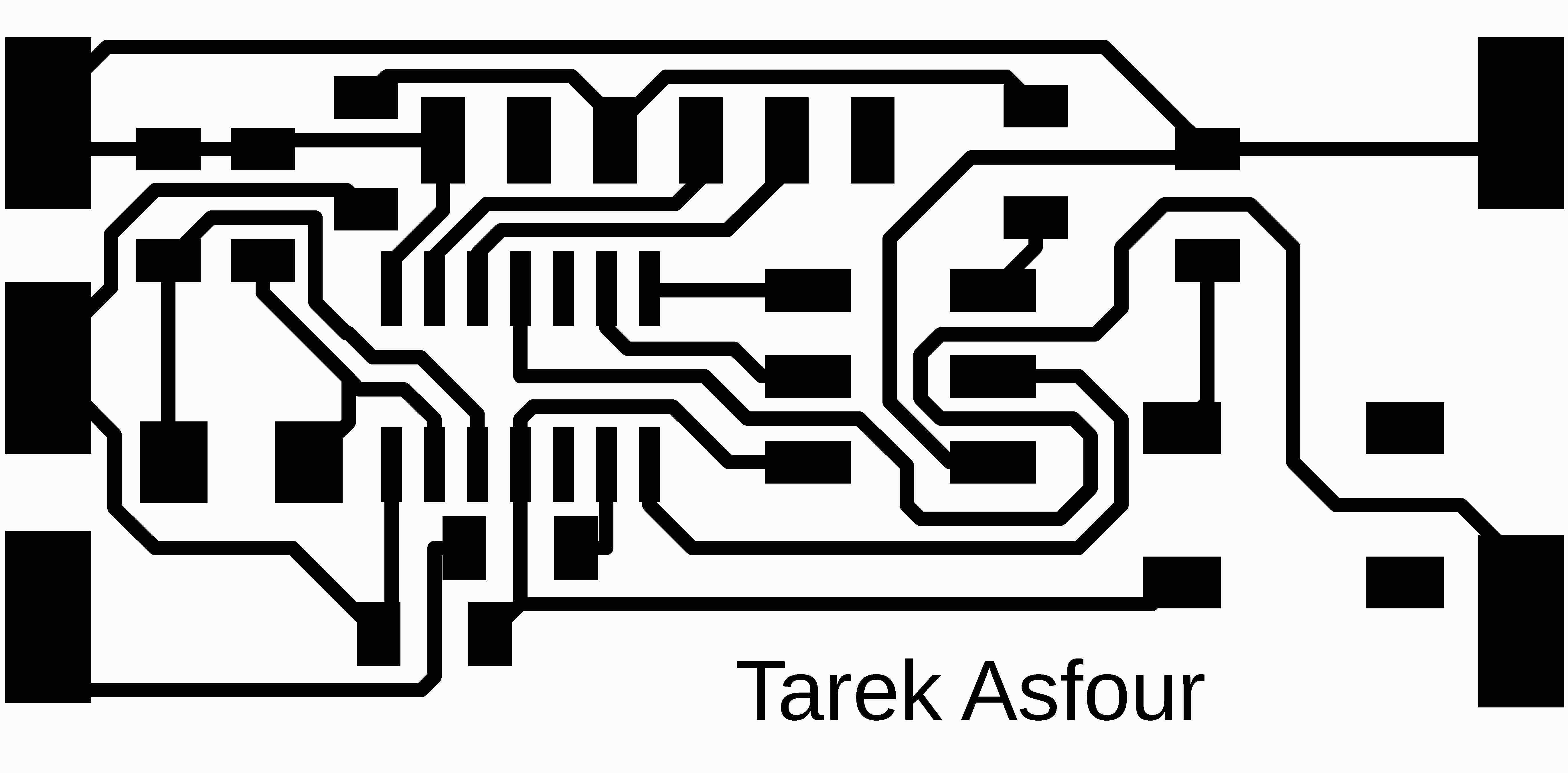
This was the image exported for the cutting of the track routes
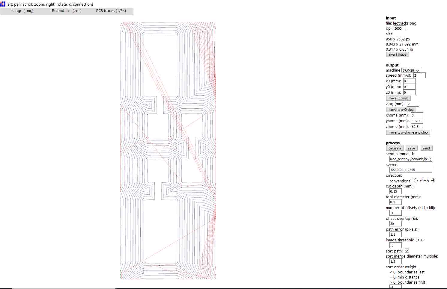
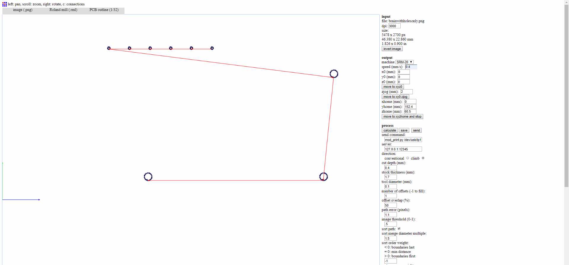
The image was then uploaded onto FabModules and processed using the following setting to output the track milling code. The endmill used here was a 0.2mm endmill. Also, after discussing the electronic production week with our mentor, Daniele gave us a trick which I used in these weeks board production. I set the offset to -1 in order to get rid of any empty copper patches, which will produce a prettier board and make soldering a lot easier.
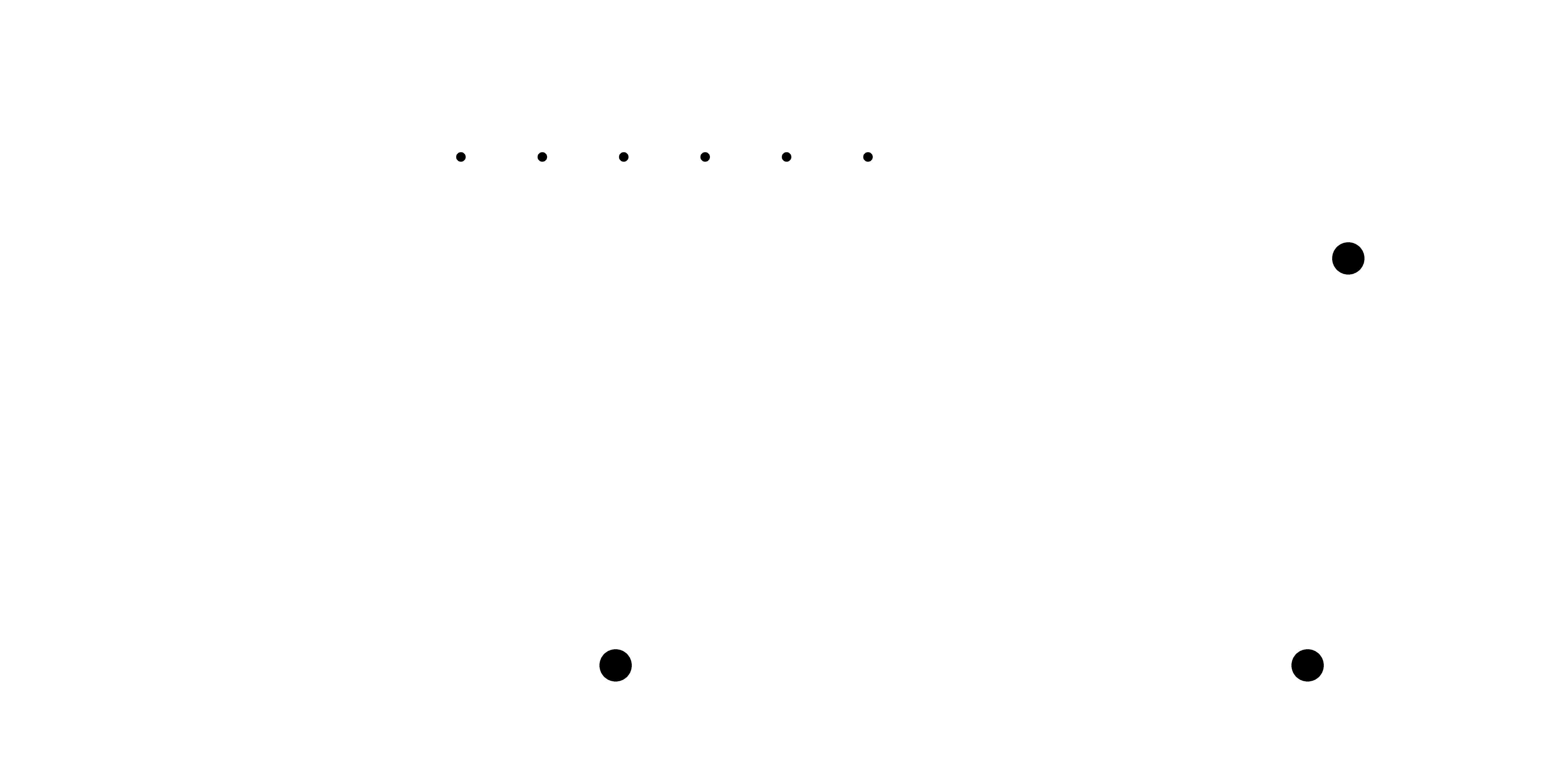
Once the track routes were milled, I proceeded to drill the holes and cut the board outline. However, each required a seperate endmill. So, I input the dimensions file into paint, filled in the outline for the drilling image. Then created another file where I covered the drill holes with a black square. Both files were processed using the same settings on FabModules but the holes drilled using a 0.8 drilling endmill and the border cut using a 1.5mm endmill
Image for drilling of holes
Image for cutting of board outline
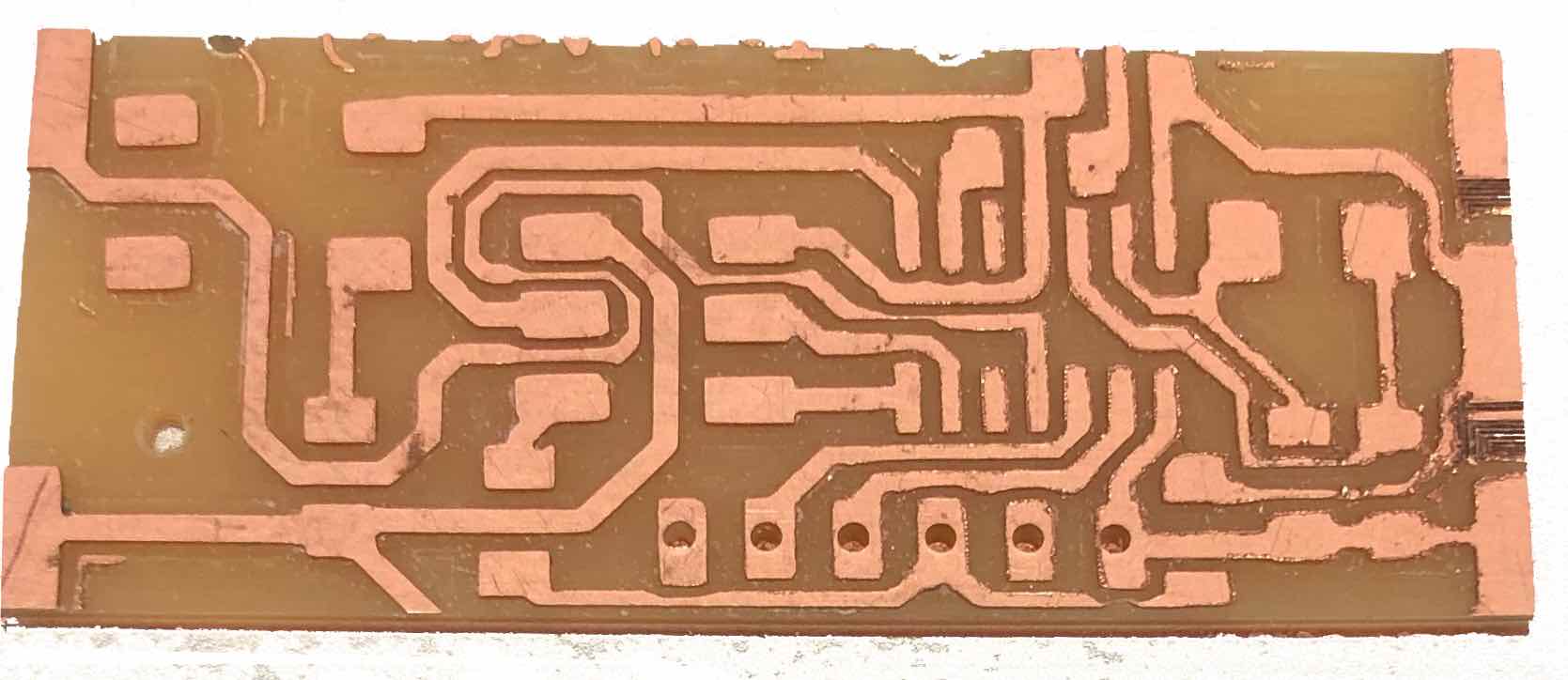
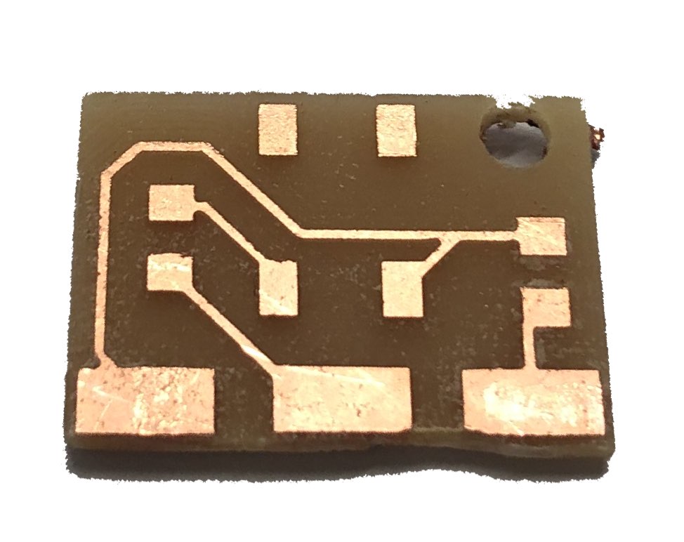
The cutting process didn't work as planned since the only available endmill was 1.5mm, it ended up cutting through the tracks on the edge and I had to start all over again. During the second attempt the milling endmill broke while cutting around the tracks and the board couldn't be recovered. Finally, on the third try the process work and my three boards were ready for soldering.
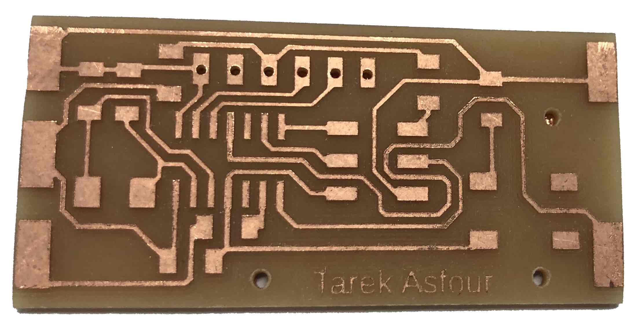
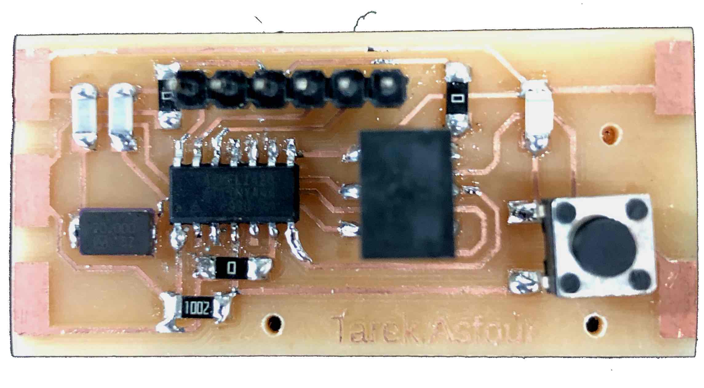
Processor board
Input button board
Output LED board
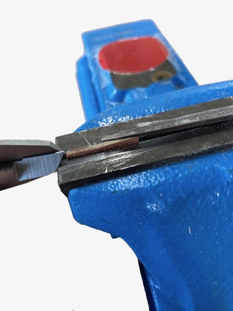
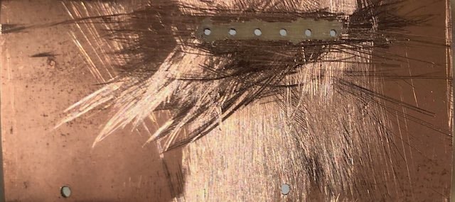
For the soldering section I had to first file the connecting edges down to approx 42 degrees as well the the bottom copper face of the through holes. I used a vice with the board sticking out 1.6 mm and a triangular needle file to achieve the correct angule of the connecting edge. I then filed the bottom copper face using a flat needle file. Once the filing was done, I followed the board drawings and schematics to correctly place and solder each of the components in place. out in relation to the drawing.
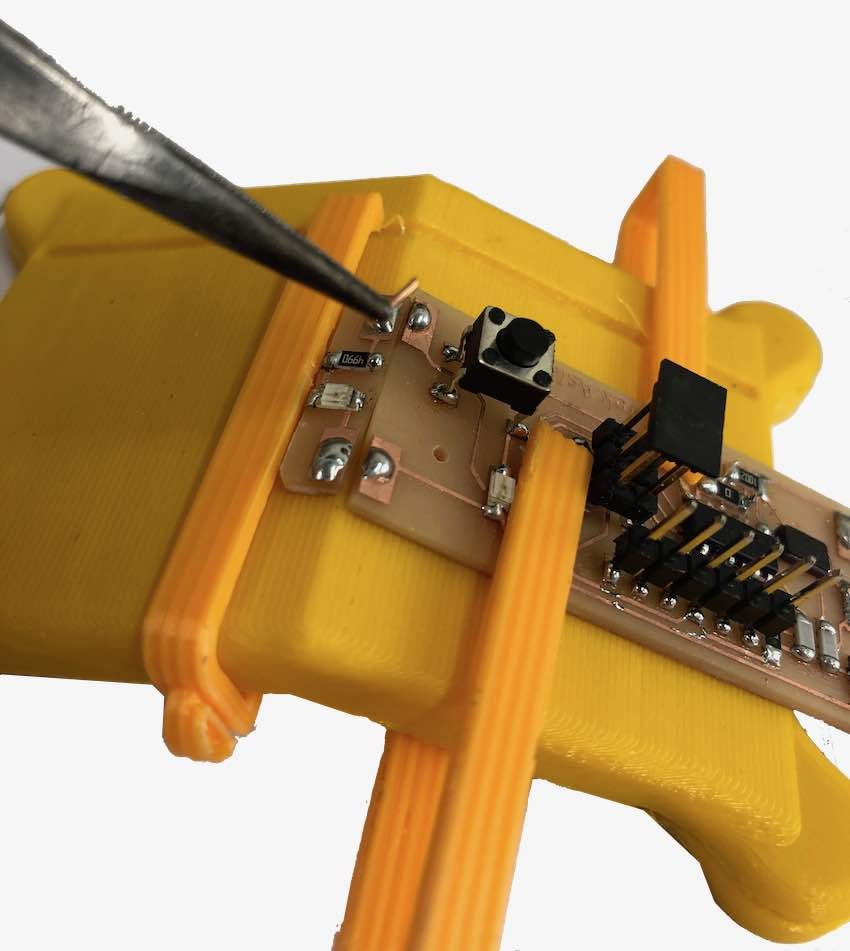
To solder the input and output boards to the main processing hello echo board, I designed and 3D printed a surface with some clips to hold the boards in place at the correct angle while I solder the boards together.
The board printed while I soldered on the components as I designed it the day before coming in to solder the components onto my board. Once it was ready I used copper wires to act as a bridge to fuse the solder from one pad to its complementary pad on the other board.
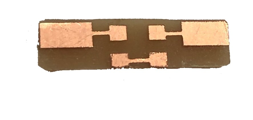
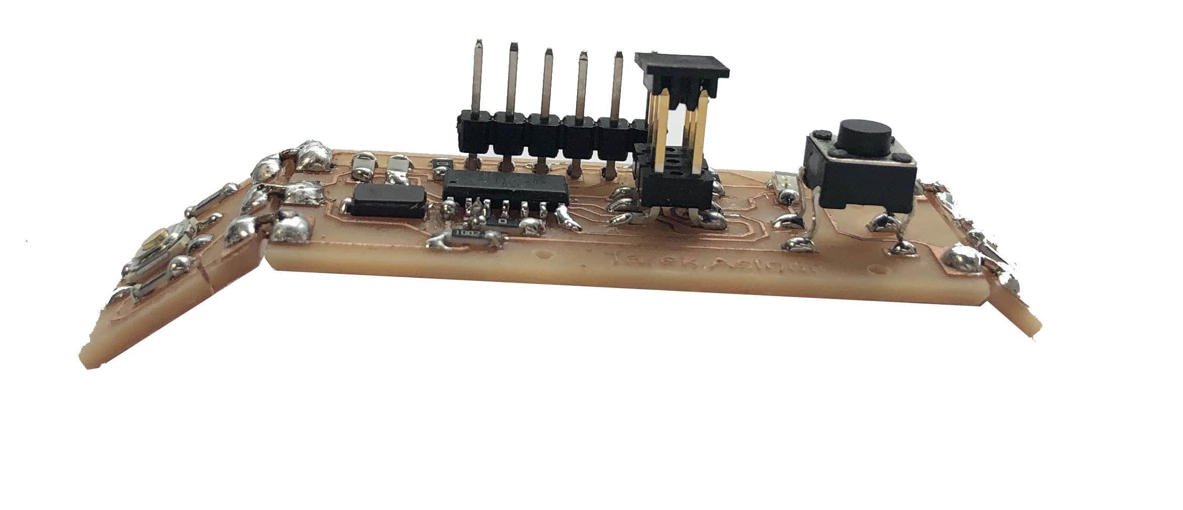
This was the final result of the three-board hello echo assembly
Programming the hello echo board
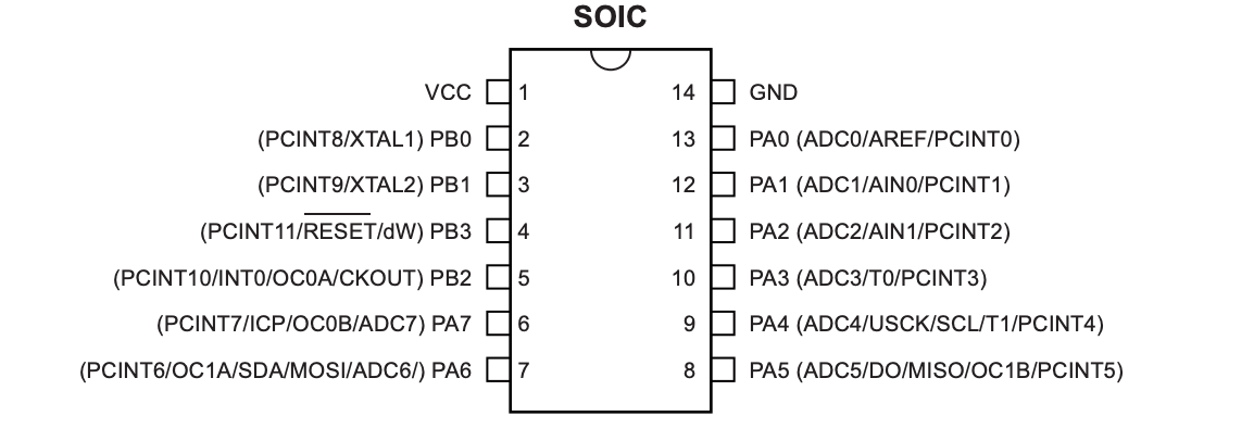
Programming the Attiny44 on the hello echo board was accomplished using and Arduino Uno acting as an ISP programmer and the Arduino IDE to program compile and upload the code. I followed the steps in this to download the required support for the Attiny44.
Before connecting the hello echo board, I chose the ArduinoISP example and uploaded it onto the Arduino Uno. Then I connected the Arduino to my Hello echo board as follows.
Arduino Pin
Attiny44 Pin
10
Reset (4)
11
MOSI (7)
12
MISO (8)
13
SCK (9)
GND
GND (14)
5V
VCC (1)
Then I opened the blink example from the Arduino examples and set the output pin to 2, which is the pin connected to the LED on my Attiny. Once I uploaded the sketch (Note:upload using programmer from the sketch menu in the top toolbar), the LED would remain lit up and not turn off. After a few hours of testing connections and diagnosing, I decided there's nothing left but to replace the Attiny44 chip.
It turns out the chip was faulty and as soon as I put in the chip and re-uploaded the sketch. The blink program worked fine.
I then wrote a short program to read the input of the button and if the button is pressed, to then turn on the LED. The code was written in the Arduino IDE, and uploaded in the same manner. The input pin was pin number 7 on the Attiny44.
             const int switchpin = 7;

const int ledpin = 2;

 int switchstatus;


// the setup function runs once when you press reset or power the board

void setup() {

  // initialize digital pin LED_BUILTIN as an output.

  pinMode(ledpin, OUTPUT)

  pinMode(switchpin, INPUT)

  switchstatus=0

}


// the loop function runs over and over again forever

void loop() {

    digitalWrite(ledpin,LOW)

  switchstatus = digitalRead(switchpin);

  if (switchstatus == HIGH){

  digitalWrite(ledpin, HIGH);   // turn the LED on

  delay(10);

  }

  else{

  digitalWrite(ledpin,LOW);

  }

}
As can be seen in the video, it worked!!
Making the bracelet
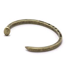
When brainstorming some application of a modular board with different inputs and outputs, I decided to go with a bracelet for its practicality, relation to the size of the board and applicability in the future on a smart modular bracelet. So I embarked on my journey to designing a bracelet to house my hello echo boards. Inspired by a bracelet that I had on, I used the same mechanism to design a 3d printed voronoi bracelet. The initial design was done on fusion and the meshing was completed on meshmixer.
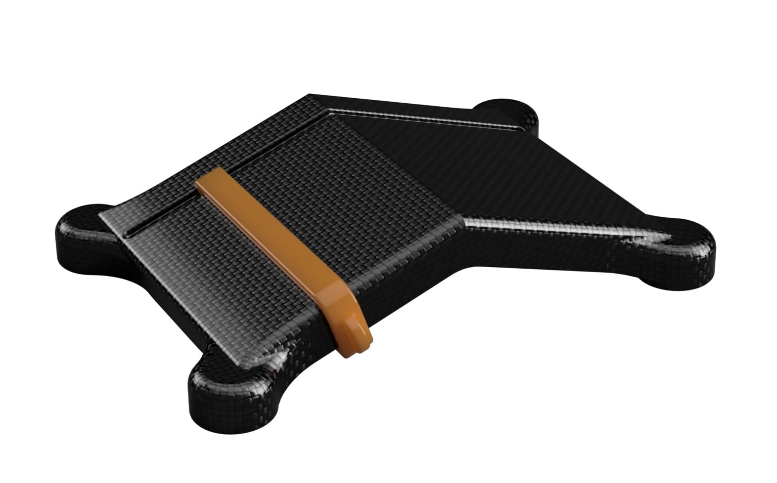
Design approach inspiration
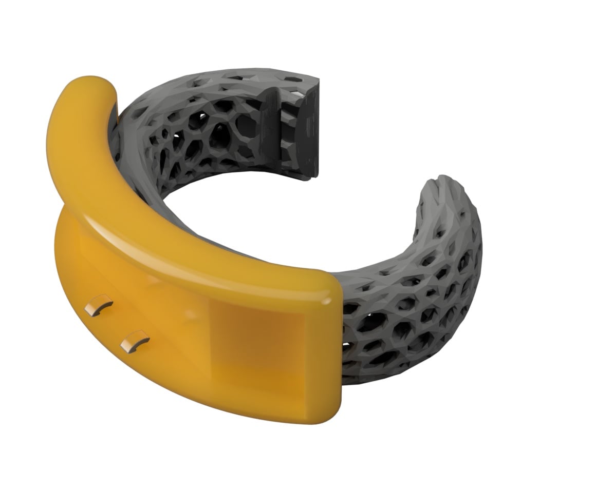
Design Render
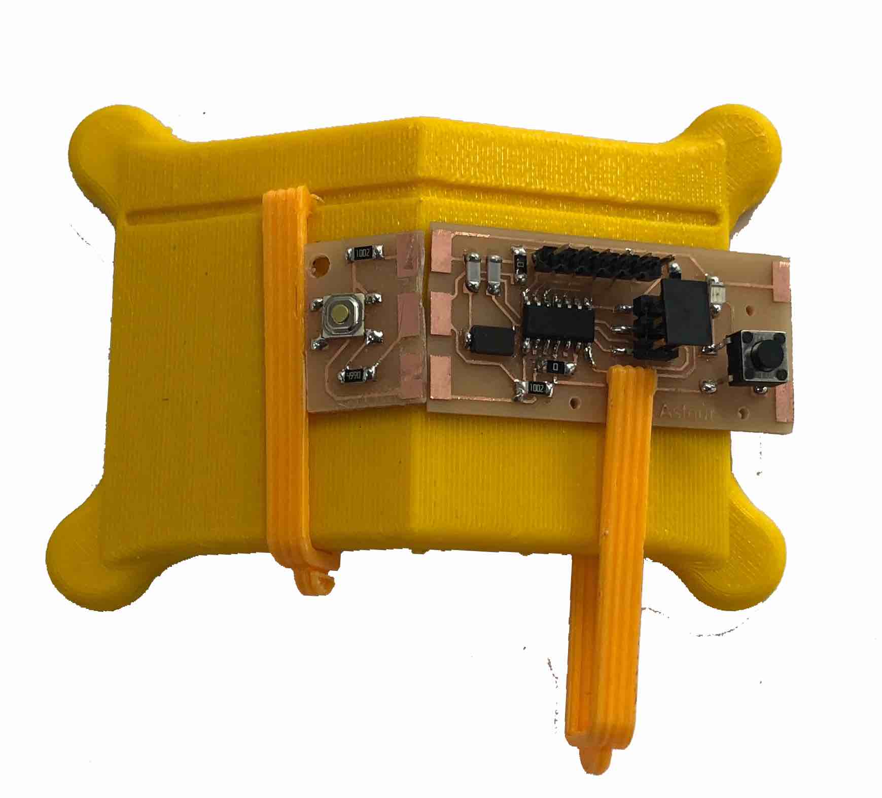
The bracelet was designed with built-in clips that lock the board in place. The cover will be designed later on as I needed to see how far the components stick out before going ahead with the design.
Files
Please find all the files required, if you feel like making your own:
-min.png)